
90' standalone MS install log

Thread Starter
Elite Member
iTrader: (5)
Joined: Jul 2006
Posts: 2,557
Total Cats: 5
From: Central California
I now have Fuel AND SPARK!!! In a nutshell, I had success when I followed the diyautotune.com miata install instructions very closely, so if you are considering installing, know that it worked for me. I have split this first post into 3 main categories:
1. modifications made to the board
2. where I connected the wires for megasquirt
3. Wiring diagrams. These are helpful for finding the right wire to attach.
I have a few more plans for the powertrain in this miata. First and foremost is to finish my engine rebuild which is mostly waiting on headwork done by myself ... which unfortunately takes a lot of time and care. Second I want to hook up the Automatic throttle body i picked up the other day. Finally I am going to need some bigger injectors. All of this should be taken care of very soon as I find myself with a lot of free time lately. I expect the powertrain to be installed and tuned by mid november. After that, I will be spending lots of time cleaning, modifying, and refurbishing the interior to suit my wants and needs. The suspension will also get some attention with coilover springs mated to the kyb's already installed, as well as a rear sway bar to match the front FM sway that is installed currently. i fully expect that I will be a regular attender of local autocross and track events locally next spring with this car.
-------------------------------------------------
BOARD MODIFICATIONS
-------------------------------------------------
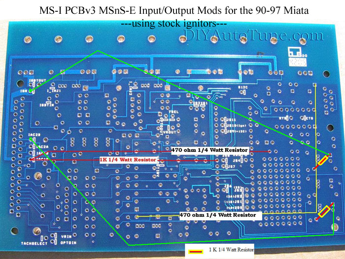
I had some trouble getting my ignition system to work, and it turned out that it was the board modifications that I first used.
This is how I modified the first time around, the same way that Kags did his, but it did not work, why I dont know?:

This is the setup that worked for me, straight from the DIYautotune website's miata install article. Note that there are some different resistors used and the spark output connections are changed on the db37 side of the board:
-------------------------------------------------
MEGASQUIRT TO ECU CONNECTIONS
-------------------------------------------------
These are the connections I'm making. See the wiring diagram link and the MS pinout picture below to see exactly what is being connected together. Also note that I have a board modified for spark and what I did is listed above, though it has been discussed before, take a look at it because I had an issue with conflicting information:
MegaSquirt inputs: ECU connections:
12v (28)----------------> white/red (1B) (shared)
gnd (8,9,10,11,19)------> 4 wires on ecu, 2 black, 2 black/lt. green (2A,2B,2C,2D) (shared)
primary rpm (24)--------> white [CKP] (2E) (shared)
secondary rpm (25)-----> yellow/blue [CMP] (2G) (shared)
coolant (21)------------> blue/white (2Q) (shared)
AIT (20) ---------------> I chose to run the GM unit and ran separate wiring, hooked gnd to one of the MS grounds
02 Sensor (23)----------> red/blue (2N) (shared)
TPS (22)---------------> red (1N) (shared)
Megasquirt outputs:
Injectors 1 (32,33)------> yellow (2U)
Injectors 2 (34,35)------> yellow/black (2V)
Spark A (36) -----------> brown (1H)
Spark B (31)------------> brown/yellow (1G)
Fuel pump selenoid (37)-> The diag. connector in the engine bay has a lt green wire, I spliced into it and connected to MS. Works great.
Idle Air control ---------> I am keeping to stock ecu to control this function for now
At this point, I have decide to keep the stock ecu to control a few basic functions such as (dashboard) tachometer output, idle control, heater control, and a few others.
-------------------------------------------------
WIRING DIAGRAMS
-------------------------------------------------
Here is a list of Miata wiring diagrams, i am obviously using the one for 1990 but i dont think theres any changes 90-93, be careful and take a peek at these before you start hacking:
http://www.madracki.com/miata/wiring.html
And on the other end of the wires, here is the handy dandy DB37 MS pinout picture, just look at the #'s by the plug and count over til you find what you want. (thanks kags)

-------------------------------------------------
SOME RANDOM PICTURES
-------------------------------------------------
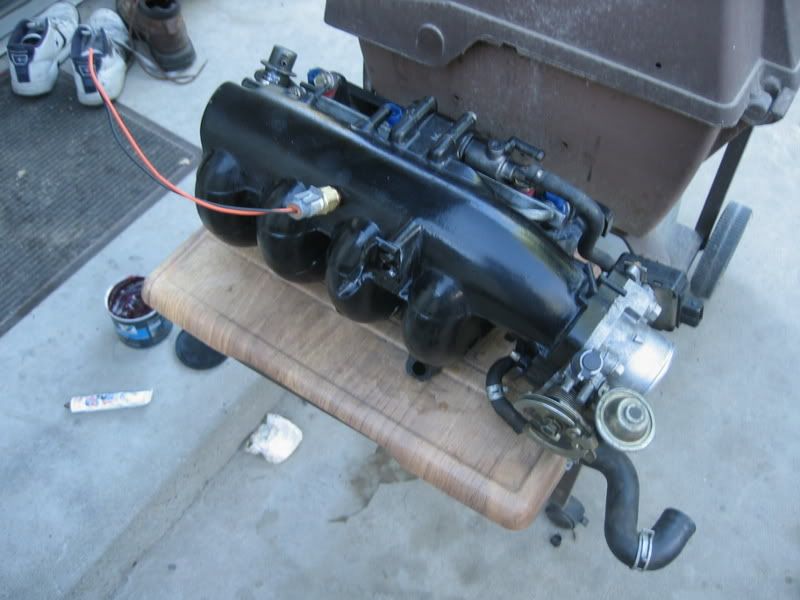
Here is my GM IAT install and mazda "brilliant black" colored intake manifold
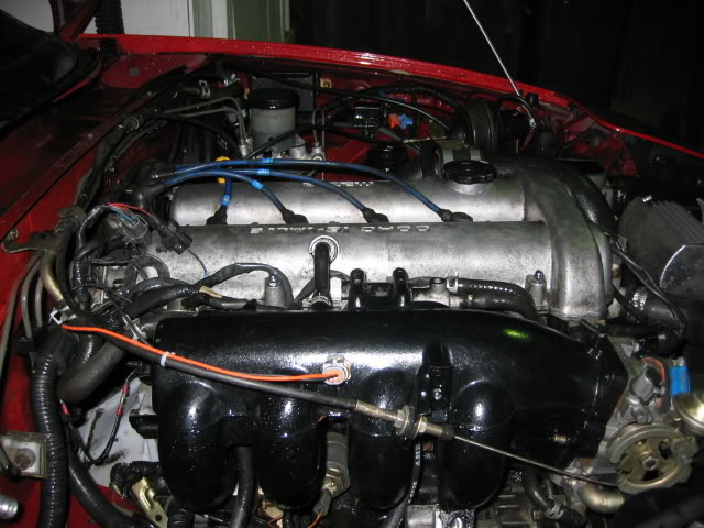
Heres how the sensor fits in the car, pretty nice eh?
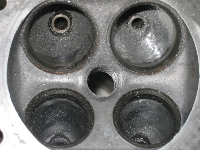
a bit of port work getting done here. top right is almost done, top left is untouched
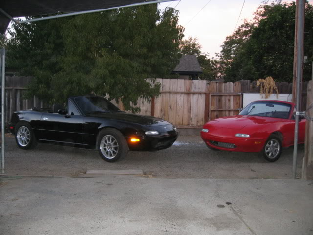
And finally my two buddies, the red is a 90 and its getting the turbo. The black one will remain pretty much stock for now.
I will continue to update until I am done, im sure that Ill find out rather quickly if my connections are off. Ill add some pictures and stuff later on when i have a bit more time.
1. modifications made to the board
2. where I connected the wires for megasquirt
3. Wiring diagrams. These are helpful for finding the right wire to attach.
I have a few more plans for the powertrain in this miata. First and foremost is to finish my engine rebuild which is mostly waiting on headwork done by myself ... which unfortunately takes a lot of time and care. Second I want to hook up the Automatic throttle body i picked up the other day. Finally I am going to need some bigger injectors. All of this should be taken care of very soon as I find myself with a lot of free time lately. I expect the powertrain to be installed and tuned by mid november. After that, I will be spending lots of time cleaning, modifying, and refurbishing the interior to suit my wants and needs. The suspension will also get some attention with coilover springs mated to the kyb's already installed, as well as a rear sway bar to match the front FM sway that is installed currently. i fully expect that I will be a regular attender of local autocross and track events locally next spring with this car.
-------------------------------------------------
BOARD MODIFICATIONS
-------------------------------------------------
I had some trouble getting my ignition system to work, and it turned out that it was the board modifications that I first used.
This is how I modified the first time around, the same way that Kags did his, but it did not work, why I dont know?:
This is the setup that worked for me, straight from the DIYautotune website's miata install article. Note that there are some different resistors used and the spark output connections are changed on the db37 side of the board:
-------------------------------------------------
MEGASQUIRT TO ECU CONNECTIONS
-------------------------------------------------
These are the connections I'm making. See the wiring diagram link and the MS pinout picture below to see exactly what is being connected together. Also note that I have a board modified for spark and what I did is listed above, though it has been discussed before, take a look at it because I had an issue with conflicting information:
MegaSquirt inputs: ECU connections:
12v (28)----------------> white/red (1B) (shared)
gnd (8,9,10,11,19)------> 4 wires on ecu, 2 black, 2 black/lt. green (2A,2B,2C,2D) (shared)
primary rpm (24)--------> white [CKP] (2E) (shared)
secondary rpm (25)-----> yellow/blue [CMP] (2G) (shared)
coolant (21)------------> blue/white (2Q) (shared)
AIT (20) ---------------> I chose to run the GM unit and ran separate wiring, hooked gnd to one of the MS grounds
02 Sensor (23)----------> red/blue (2N) (shared)
TPS (22)---------------> red (1N) (shared)
Megasquirt outputs:
Injectors 1 (32,33)------> yellow (2U)
Injectors 2 (34,35)------> yellow/black (2V)
Spark A (36) -----------> brown (1H)
Spark B (31)------------> brown/yellow (1G)
Fuel pump selenoid (37)-> The diag. connector in the engine bay has a lt green wire, I spliced into it and connected to MS. Works great.
Idle Air control ---------> I am keeping to stock ecu to control this function for now
At this point, I have decide to keep the stock ecu to control a few basic functions such as (dashboard) tachometer output, idle control, heater control, and a few others.
-------------------------------------------------
WIRING DIAGRAMS
-------------------------------------------------
Here is a list of Miata wiring diagrams, i am obviously using the one for 1990 but i dont think theres any changes 90-93, be careful and take a peek at these before you start hacking:
http://www.madracki.com/miata/wiring.html
And on the other end of the wires, here is the handy dandy DB37 MS pinout picture, just look at the #'s by the plug and count over til you find what you want. (thanks kags)
-------------------------------------------------
SOME RANDOM PICTURES
-------------------------------------------------
Here is my GM IAT install and mazda "brilliant black" colored intake manifold
Heres how the sensor fits in the car, pretty nice eh?
a bit of port work getting done here. top right is almost done, top left is untouched
And finally my two buddies, the red is a 90 and its getting the turbo. The black one will remain pretty much stock for now.
I will continue to update until I am done, im sure that Ill find out rather quickly if my connections are off. Ill add some pictures and stuff later on when i have a bit more time.
Last edited by akaryrye; Oct 18, 2006 at 03:44 AM. Reason: Updated
Reply
 0
0

0


Junior Member
Joined: Nov 2005
Posts: 252
Total Cats: 0
From: Down Under
Reply
0
0


Junior Member
Joined: Nov 2005
Posts: 252
Total Cats: 0
From: Down Under
Check the ignitor as well as the coils. If anything has gone, it will probably be the ignitor.
Are you getting any tach readings on your laptop screen when you try and start the car? If it isn't reading anything then it could be your CAS connections. If the tach (on the laptop) is yellow then you have a corrupt msq and that could easily result in no spark.
Also if your msq was setup for a V8, then have you correctly done the wheel decoder settings? And have you changed the outputs so you are getting spark in the right connectors/wires?
Reply
0
0

Thread Starter
Elite Member
iTrader: (5)
Joined: Jul 2006
Posts: 2,557
Total Cats: 5
From: Central California
Yes i am getting a tach signal, coolant signal, AIT signal, MAP signal. However, I didnt mention this before, but the Injector duty cycle gauge didnt move at all that i could notice, and i also dont think that injector pulse width was moving either. Though it is probably just because of the low rpm and fuel demands, I want to make sure.
This is exactly the reason im getting this ironed out before the new motor goes in!
Edit: Note that I am no longer getting a tach signal on my wiring... why, im not sure
This is exactly the reason im getting this ironed out before the new motor goes in!
Edit: Note that I am no longer getting a tach signal on my wiring... why, im not sure
Last edited by akaryrye; Oct 11, 2006 at 10:34 AM.
Reply
0
0
Junior Member
Joined: Nov 2005
Posts: 252
Total Cats: 0
From: Down Under
There is only one ignitor and it is on the passenger's side of the engine bay, near the main fuses. It is a small rectangular black box thingy, sort of the same shape as a box of matches. Check your wiring diagram for the colors of the wires going into the ignitor, and match that to the wires going into the ignitor in the engine bay.
Reply
0
0
Thread Starter
Elite Member
iTrader: (5)
Joined: Jul 2006
Posts: 2,557
Total Cats: 5
From: Central California
got it squirting ... and sparking woot. Drove it to the gas station and back in fact! Drives pretty good but i can tell that it needs a bit of tuning to get it running right. Looks like its time to get crackin on my cylinder head so i can bolt the engine together and start enjoying boost (just in time for the winter :( ... oh well it will be debugged by spring!)
Check the first post, I have updated it.
Check the first post, I have updated it.
Reply
0
0
Thread Starter
Elite Member
iTrader: (5)
Joined: Jul 2006
Posts: 2,557
Total Cats: 5
From: Central California
Well its been a few days since I have updated where I am at. I had been driving a bit around on the megasquirt with no problems at all, but have not done much until yesterday and today since I had to do a waterpump/timing belt on my black car and after that I was spent for a day or two. Finally hooked up the LC1 wideband and was eager to go out tuning, but must have caused a problem with the wiring because it has decided to not start at all now. I didnt have the energy tonight to debug everything, but I am not getting any IDC or pulsewidth readings. Tomorrow ill go over my wiring and make sure nothing slipped out. It is frustrating, but this is the reason why MS is able to be cheaper than the others I guess. Is four to seven hundred dollars worth my time and trouble? Hell yea. Ill get it working just fine and dandy in no time.
Also I have 550 cc injectors ($200) in the mail from a fellow forum member, kungfu jesus, and a pending custom catback exhaust install next week with a glasspack muffler (quoted $225 for parts and labor). There goes another $525! Thats why I gotta work two jobs. After that I still need to buy a headgasket, valve seals, and get the head surfaced and the valves reground ... well im considering just lapping all the valves to save some money. we will see
In the future, I pan on doing boost control and idle control with megasquirt.
Reply
0
0
Thread Starter
Elite Member
iTrader: (5)
Joined: Jul 2006
Posts: 2,557
Total Cats: 5
From: Central California

Well, im bringing this thread back from the dead because shortly after I made the last post, i started experiencing problems which forced me to return to using the stock ecu. At the time I wanted to finish my motor rebuild and get the suspension sorted better. Well ... that stuff is done. I have my suspension sorted, good rubber, turbo is reinstalled on a rebuilt motor, and Im running a measly 4psi on fuel only. The drivability sucks, gas mileage sucks, and its not an optimal solution.
Anyway, the recent megasquirt threads prompted me to pull the stuff out of the corner where they have been sitting for a few months:
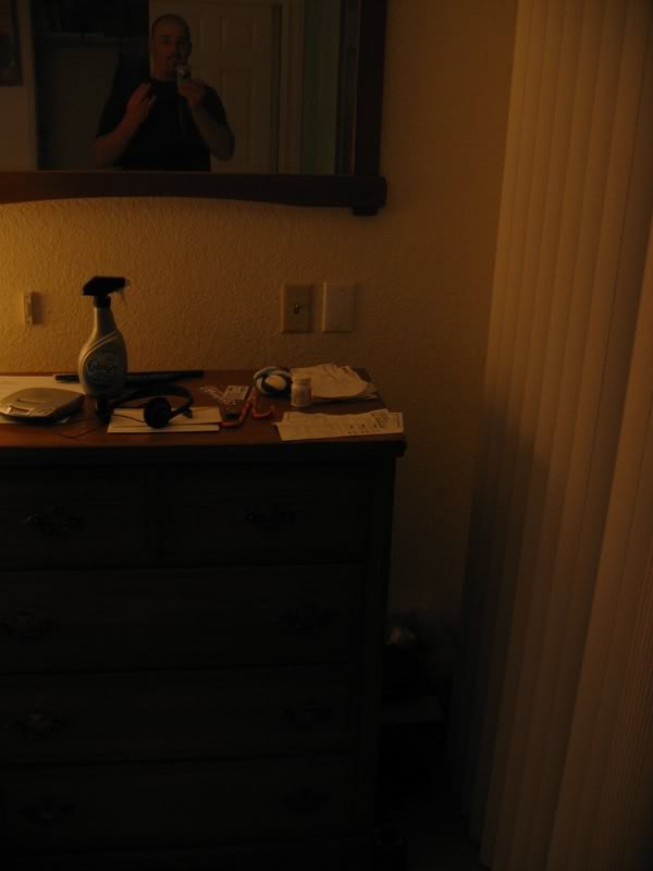
That is me up top. if you look to the bottom right corner, theres a little box.
Hmm what could be be in there?
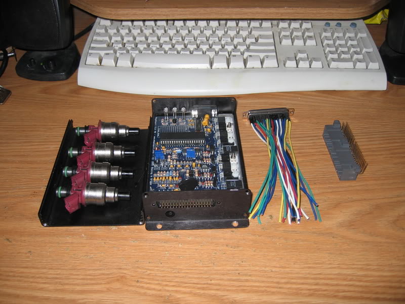
Thats right, I just need to figure out how to connect these things together though:
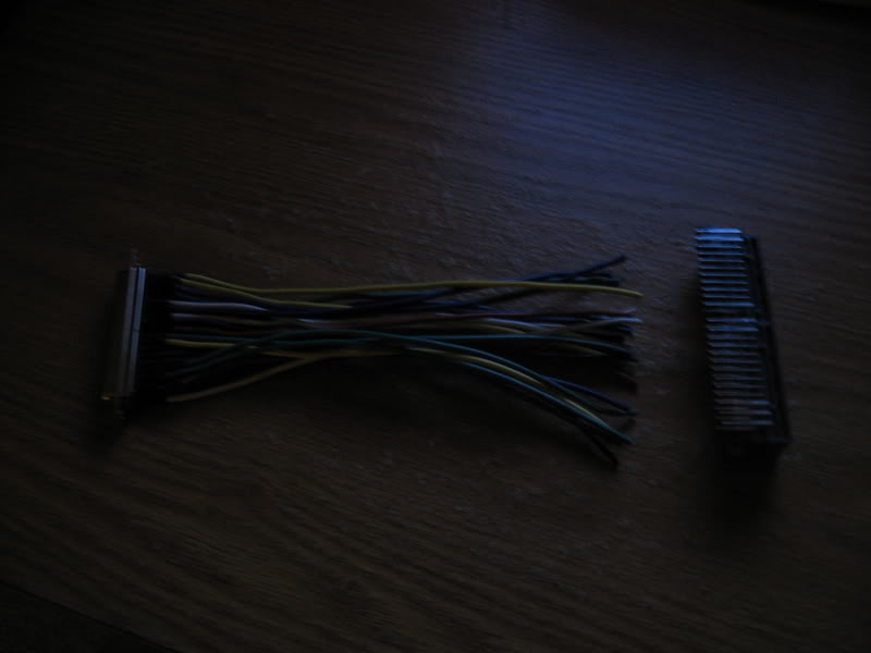
Any ideas on how to connect those harnesses together? are there special crimps for it or something?
Reply
0
0

cut off little pieces of heatshrink about 1/3" and slip them down each wire. Solder on the wires that need to be soldered on. push heatshrink over solder joint. heat heatshrink. Complete.
If you wait like a day I can show you the harness that I am making for Newsauce for the MS I am building him. I am using the same ecu connector you have except I also have the male ends so that it can be run parallel with the stock ecu. Its very simple, while I'm doing it I'll document the pins you need to solder what to. I should be able to finish it tomorrow night after classes and a trip to bestbuy.
If you wait like a day I can show you the harness that I am making for Newsauce for the MS I am building him. I am using the same ecu connector you have except I also have the male ends so that it can be run parallel with the stock ecu. Its very simple, while I'm doing it I'll document the pins you need to solder what to. I should be able to finish it tomorrow night after classes and a trip to bestbuy.
Reply
0
0


