When you click on links to various merchants on this site and make a purchase, this can result in this site earning a commission. Affiliate programs and affiliations include, but are not limited to, the eBay Partner Network.
I hate eccentrics, I hate how they slip I hate how hard they are to access while aligning the car on the ground and I hate their limited range of adjustment. I'm less than a year into Miata ownership but have been playing with race cars for going on two decades now so I've seen some things in other racing venue's that gave me an idea for the NA/NB chassis. These types of control arms are not a new thing, they're on just about every late model dirt track car in the country, but alas there are no off the shelf kits that will fit a Miata so I went about fabricating the necessary bits.
First rough mockup with the primary parts, as you can see the heims are just about out of articulation. You can also see the "seals-it" dust shields I was going to use before I realized I needed high misalignment adapters.
First, I needed some adapters to be able to use 1/2" heims for the inner pivot points so I turned out some reducer bushings to be able to use a standard 3/8" bolt in place of the metric upper control arm long bolt.
Stainless sucks to machine, got the holes a little offset in these prototypes but with the adjustable nature of the control arm it just won't matter.
I also procured some high misalignment adapters as well, stock heims only have ~30 deg of articulation, these allow for another 30 degrees on top of that. They do reduce a 1/2" heim to 3/8" but in this application a 3/8" bolt is plenty strong enough. The machining on these make me envious.
A little trick I learned over the years is to pack the heim with marine grease, I also use a solid metal heim as I find the teflon or kevlar races in the expensive ones hammer out quickly and develop slop. Of course the downside of the solid heims is squeeking in short order once they get wet and wash out the grease so I combined this water resistant grease along with the full dust boot you see below to make an almost street friendly heim setup. I expect to get 10 to 15k miles out of these and at 6$ a pop.....I can afford to replace them that often.
Completed heim with misalignment adapters, These full boots are engenius, I honestly believe they are the key to running heims on the street for any length of time.
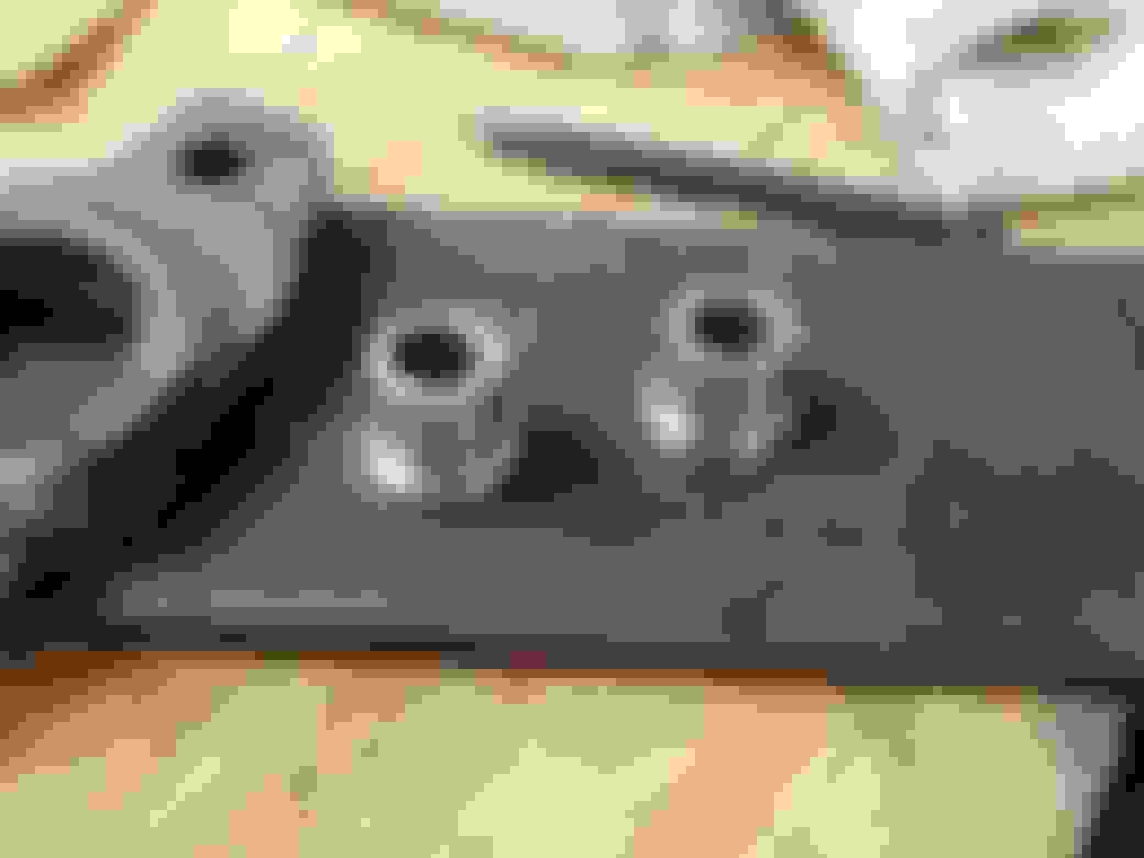
Next up is the key piece of hardware to make this all work, I needed a press fit ring for the problem solver replacement moog ball joints (These are only for NA's, but more on that later) so these rings were turned out on my mini lathe from heavy wall tube. Then I cut out the tab from 3/8" plate for the clevis, and cut the head off a 5/8" bolt for the other connection. I'm emulating what is available for the dirt track cars here, but with a Miata specific ball joint and connection angles.
You can see these ball joints come with a snazzy snap ring to capture the ball joint, this combined with a .007" press fit means these are nice and snug. The dust boot installs on top of the snap ring.
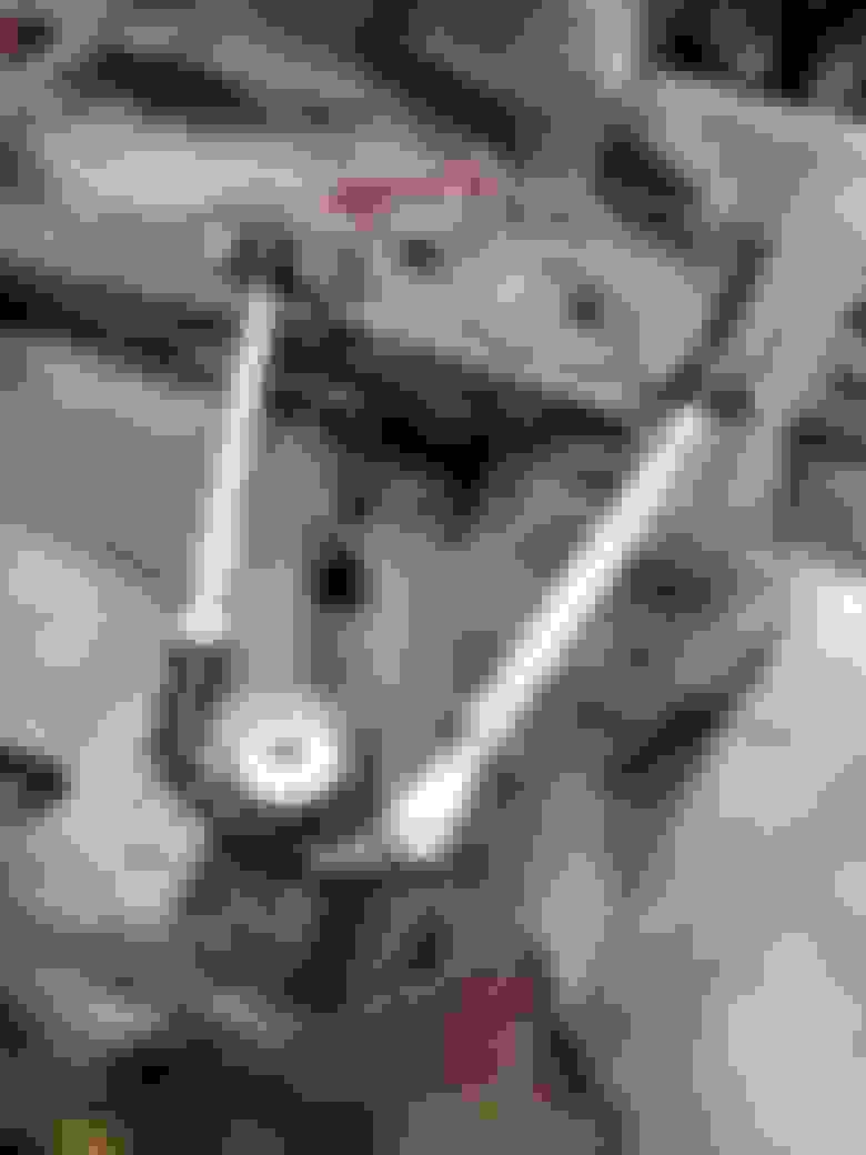
Finally, the money shot of the whole assembly mocked up on my spare subframe. Adjustment just requires you to loosen the two jam nuts and the cinch bolt on the clevis then you can crank the swedged tubes by hand most of the time. Initial mockup on my NB shows I can bury the tire into the coilovers so that's the only thing limiting my camber range. Caster is also very adjustable, no more compromising one setting to allow for another. I'll be tack welding the eccentrics now that I can make all my adjustments at the upper A-arm.
One last issue, NB's use a longer shank on their ball joint. So as you can see here the castle nut has full thread engagement but doesn't allow enough room for the cotter pin. I drilled a small hole in the spindle and was able to get a piece of .030" wire through the cotter pin hole effectively creating a safety wire setup. The steel wire is temporary until I can source some stainless.
That's great work and since you have the know-how and tools I'm sure it was quite inexpensive to build other than the time you have in it.
But IMO, you should have spent your time on the lower control arm. You would still be able to accomplish the alignment changes just as easily but would have reduced more weight (although only half of it unsprung), and as you have already mentioned, would not have limited your tire to body contact on the shock tower. Hopefully you build some lowers.
And while they may not be adjustable for caster without some disassembly, the aluminum v8roadsters control arms are available OTS for $500.
Making the lower control arms adjustable is a whole nother ball of wax. With the spring and shock acting as a bending moment in the lower arm the forces involved pretty much prevent the use of heim joints or threaded sleeves. Heims and threaded connections are strong when loaded axially, but can loose up to 2/3rds of their strength when loaded in bending. Case in point, I built an SAE mini baja racer in college, we had a 3/4" heim at the spindle and 5/8" at the chassis mount. We snapped every one of those heims multiple times with a 300 lb. buggy. Access for adjustment would be much better though, but the threaded portions would need to be 1 1/4" or larger for me feel it's safe.
When I said I was limited by the tire to spring interferences, I was sitting at 4.7 degrees of camber so unless you're trying to tuck negative offset wheels there should be plenty of adjustment. You could also get the extended lower ball joint and then adjust the upper arm out to gain more clearance for a given camber setting.
The V8 roadster arms are a thing to behold, not sure I like the shim arrangement, would still need to pull a tire to add the shims. At 500$ I'll keep fabricating!
I run a 275 tire for autox and 3* camber. Plus its an autox car so you don't want it any wider than it has to be.
I fully get your gripe with eccentrics but from my POV, adjustable uppers are not the way to go. If I were running a 205 tire then yes.
And $500 for aluminum heim control arms is reasonable if you ask me. I can't run them in my class because of the heim's but if I could there would be no question.
I still look forward to you tackling the lower control arms. Something tells me you like to fabricate.
I have thought about ordering these parts from speedway to see if I could make them work. Nice job.
And I agree about the upper arm being adjustable. The lower is a magnitude of order more complicated. People are cracking gusseted V8R arms with bushings...
Thanks Sean, you've nailed my supplier for most of the parts. Hardest part to find believe it or not is a 9" long 3/8" bolt that wasn't made out of pot metal.
Just got finished aligning the car for the first time with these, at the risk of blowing my own horn it was amazing how much easier it was. With the car sitting on the ground I could lay down and reach my arm up to the A-arm and easily make adjustments while I watched my camber gauge. I was able to hit my numbers dead nutz withing a few minutes. With the tires sitting on top of a couple of plastic walmart bags (magazine's work too) I was actually able to swing the tire by hand so I could make adjustments and sweep the tire to get my caster readings pretty easily. Looks like I can get any caster setting between 0 and 10 degrees and still be able to get as much as 4 1/2 degrees of camber and this is with 15x9's and 225 tires. Mission accomplished......now on to the rear arms.....did I mention I HATE eccentric bolts?
Im don't see why 7075 or even 6061 wouldn't work for the spacers. both are cheaper than most flavors of SS, not to mention, much easier to machine; especially on a lil' hobby lathe.
What is the ID of the heims? Could you fit a 12mm bolt? For some reason metric bolts that length seem to be much cheaper and easier to get in a decent grade, like 12.9. McMaster-Carr
In normal use, that bolt doesn't need to be very big, especially the factory 15mm. but 3/8" does seem a little small. I think if a wall just looked at your tire wrong, it could bend. Any reason you didn't do a 1/2" bolt and sleeve the subframe?
I considered 6061, but the price difference for an 18" piece was about the price of a large fry so I went with the stainless. It's not that bad to machine, second set of bushings I made I was able to center the hole much better by starting the hole with a centering bit.....yeah that was smart huh.
The swedged tube I am using is 1/2" on one side and 5/8" on the other which I needed on the ball joint end for the 3/8" clevis so I was somewhat stuck with a 1/2" heim, I also needed the additional articulation of the high missalignment adapters which step you down 3/8". I started out using a 1/2" bolt, but the reducer bushing was very thin with a wall in the .030" range. This was both difficult to machine well and I worried about popping the head off the reducer bushings.....even though there is really no reason it would. In the end I got comfortable with the 3/8" bolt due to the fact that ball joint necks down to .420" at the base of the ball. Two .375" sheer planes will be much stronger than the ball joint so I left it alone. If you want to get all enginerd this LINK has some sheer numbers you can play around with. Even if you consider the ball joint to be on the same plane as 7/16" ARP bolt (.4375") two grade-5 3/8" bolts will still be stronger.
If I did it over again I might consider a strait 5/8" swedged tube and using a 12mm bolt. This would require machining the adapter bushings differently obviously and you would end up with .045" wall in the sleeve which is better. It would also require me to drill out the missalignment spacers.....not a big deal.
Making the lower control arms adjustable is a whole nother ball of wax. With the spring and shock acting as a bending moment in the lower arm the forces involved pretty much prevent the use of heim joints or threaded sleeves
Could you explain this further? Looking at the connection, the shock is attached to the LCA with a bushing bolted between two tabs. The only bending moment in the "roll" direction would be any bind between the bushing and shock eyelet, and in the "pitch" direction would be bind from the "squish" of the bushing, no? I don't think either bending moment is actually desirable, is it? Wouldn't a heim jointed shock eyelet be superior?
Could you explain this further? Looking at the connection, the shock is attached to the LCA with a bushing bolted between two tabs. The only bending moment in the "roll" direction would be any bind between the bushing and shock eyelet, and in the "pitch" direction would be bind from the "squish" of the bushing, no? I don't think either bending moment is actually desirable, is it? Wouldn't a heim jointed shock eyelet be superior?
You are misunderstanding the problem. It's the bending moment of the arm, caused from the shock.
Could you explain this further? Looking at the connection, the shock is attached to the LCA with a bushing bolted between two tabs. The only bending moment in the "roll" direction would be any bind between the bushing and shock eyelet, and in the "pitch" direction would be bind from the "squish" of the bushing, no? I don't think either bending moment is actually desirable, is it? Wouldn't a heim jointed shock eyelet be superior?
the shock/spring assy is trying to bend the arm in half between the ball joint and suspension bushings.
Never mind that, the lower takes the majority of lateral g forces and braking forces. So in addition to the shock/spring vertical moment, there is also horizontal moment trying to push the front bushing in or out while the rear is getting the opposite force, all focused on that 90* bend in the arm that V8R has had to gusset the F out of.
Exactly, it's hard to visualize the load paths but by introducing the spring and shock into the middle of the A-arm imparts a tremendous load on the joint. Heim's only work well when loaded radially, meaning both ends need to be able to pivot through the load path. That's a heck of a sentence, but basically the load has to be applied through a pivot of some sort. So in the case of the upper control arm it pivots on the ball joint and it pivots on the heim therefore the load will only be "radial" through the heim. Now think of what happens if you put a force downward through the arm, your now trying to bend the threads or pop the ball out of the heim. I went looking for the actual load rating in bending, which is refered to as static load, heim companies quit publishing them, I found one reference to 10% of axial ratings.......yeah don't load heims in bending it's a bad deal. I'll have to find the picture of the mini baja buggy with both lower a-arms just dangling from a hard landing.
I initially envisioned a lower mount that used a jack bolt to push the mount in and out instead of a eccentric, but it was just getting too complicated and required too much welding on the sub frame. This was the easy button for me and is a tried and true design in the circle track world.
I drove the car to work today and aimed for every pot hole I could find......they didn't kill me.
Why couldn't the machined piece not use the threaded rod and just mimic the ball joint on each side?
If I'm understanding your question correctly, you need to allow for the angle of two adjusting arms to change for different caster and camber settings. Using threaded rod welded on both sides would not allow this and would bind. The clevis cures this issue.
Just to clarify, I was actually asking the reverse. Why didn't you use the clevis on both sides of the BJ instead of just on one and then the rod. i.e. no rod just clevis?
I had presumed the clevis and Heim joints are adjustable length wise so "adjustment" isn't the answer but maybe that is why......
Ahh gotcha, in that configuration even with both jam nuts tight the ball joint would rotate in the clevis' oscillating the whole assembly forward and back. It's hard to imagine but the clevis doesn't have enough clamping force to resists this motion, with a single clevis you get the ability to adjust without the whole thing flopping around.
I'm still not seeing the issue. You have a vertical load point on the end of the arm, from the wheel and spindle. You have another load point at the shock mount. You have another vertical load point at the chassis end of the arm. Are you saying that the spherical bearing doesn't like the bending load on the threaded portion of the eyelet?

 09-03-2016, 10:53 PM


 6
6


