Chiburbian's 01' Lots of potential, no follow-through build
 12-15-2014, 09:46 PM
#241
Elite Member

Thread Starter
iTrader: (1)
Join Date: Feb 2008
Location: Loganville, GA
Posts: 2,331
Total Cats: 202
Hot side is coming together...
Next step is intake, bracket for waste gate, AIT bung, and cold air box. Once that is all done it's being sent to powder coat.
Next step is intake, bracket for waste gate, AIT bung, and cold air box. Once that is all done it's being sent to powder coat.

Reply
 1
1

1
12-15-2014, 11:01 PM
#242

That is very nice.
We've welded a vband onto a cast housing like that before too - still holding up a couple years later IIRC.
That coldside route is about as smooth as its ever gonna get, and the cold side is almost as good.
Overall loving the fmic setup, this thing is ready for some massive flow
We've welded a vband onto a cast housing like that before too - still holding up a couple years later IIRC.
That coldside route is about as smooth as its ever gonna get, and the cold side is almost as good.
Overall loving the fmic setup, this thing is ready for some massive flow
Reply
0
0

 12-16-2014, 04:00 PM
#244
Elite Member
Thread Starter
iTrader: (1)
Join Date: Feb 2008
Location: Loganville, GA
Posts: 2,331
Total Cats: 202
https://www.miataturbo.net/build-thr...7/#post1024323
Reply
0
0
12-17-2014, 03:49 PM
#245
Elite Member
Thread Starter
iTrader: (1)
Join Date: Feb 2008
Location: Loganville, GA
Posts: 2,331
Total Cats: 202
I have been trying to read the various catch-can threads out there.
Someone please spoon feed me?
But first I will try and describe what I believe the most common catch can setup is: Vacuum hose from intake manifold to PCV valge to Valve Cover. On Drivers side, hose from valve cover to Catch Can to inlet in turbo intake piping...
Am I close?
Are there passages between the valvetrain area to the crankcase through the block/head? Is there a need (aside from drain possibly) to have a line going from lower portion of block to inlet of catch can? Or, does the crankcase ventilate into the valvetrain area and thus the pressure can be handled by the drivers side valve cover hose (to the catch can)?
When my turbo was pulled to do this upgrade, my guy found a bunch of oil in the intake tube and in the turbo, so certainly the driver side valve cover discharge IS releasing some oil.
Any links to pictures of descriptions of setups I should copy? (I have been reading the threads but they are pages upon pages of discussion and I just want an answer to how to do it right).
++++++
From the Catch can thread:
++++
Just posted this in the catch can thread:
If I wanted to NOT vent to air, would the following be a big deal?
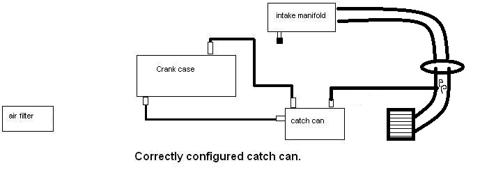
Has anyone tried using something like a "slash cut" in the intake tract to create some amount of vacuum? (not enough to act like a pump, but enough to draw the vapors out and burn them up?)
Someone please spoon feed me?
But first I will try and describe what I believe the most common catch can setup is: Vacuum hose from intake manifold to PCV valge to Valve Cover. On Drivers side, hose from valve cover to Catch Can to inlet in turbo intake piping...
Am I close?
Are there passages between the valvetrain area to the crankcase through the block/head? Is there a need (aside from drain possibly) to have a line going from lower portion of block to inlet of catch can? Or, does the crankcase ventilate into the valvetrain area and thus the pressure can be handled by the drivers side valve cover hose (to the catch can)?
When my turbo was pulled to do this upgrade, my guy found a bunch of oil in the intake tube and in the turbo, so certainly the driver side valve cover discharge IS releasing some oil.
Any links to pictures of descriptions of setups I should copy? (I have been reading the threads but they are pages upon pages of discussion and I just want an answer to how to do it right).
++++++
From the Catch can thread:
Brain has the dumb again.
The op's pcv setups are perfectly adequate for N/A cars and milde turbo setups. We really only run into problems with crank case venting in 1 case. Big power turbo cars making significant lateral grip. For cars like this we delete the pcv port on the head because if we leave it open it just dumps oil out on sustained corners. See my car or Bundy's for some of the most advanced crank case venting on the site. I no longer have a pcv valve because my car doesnt see significant time cruising, if it did I'd run one. I have a massive AN fitting on the head, with the small port in the head baffling drilled out And I tapped the block for a 1/2" NPT fitting just above the starter to run another -10 an line. Both go to my air/oil separator and into my pre-turbo intake with a slashcut. At worst the slashcut doesnt work in the intake and I still get the slight vacuum created between the turbo and the air filter. I just didnt feel like doing the exhaust slashcut at this time, and its also illegal for every raceclass above mine for some stupid reason.
You pretty much dont want to just vent both sides of the engine to air without pulling any vacuum unless you're incredibly lazy.
Just posted this in the catch can thread:
If I wanted to NOT vent to air, would the following be a big deal?
Has anyone tried using something like a "slash cut" in the intake tract to create some amount of vacuum? (not enough to act like a pump, but enough to draw the vapors out and burn them up?)
Last edited by Chiburbian; 12-17-2014 at 04:14 PM.
Reply
0
0
12-18-2014, 12:17 PM
#246
Senior Member

Join Date: Mar 2011
Location: South Chicago
Posts: 697
Total Cats: 26
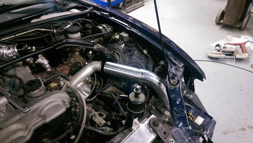
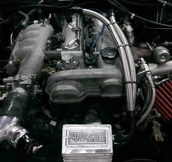
I havent routed my pcv valve to my catch can yet because I haven't figured out a clean way of doing-so where it's mounted. But here's an idea of my current setup. Ignore the messiness in the bay, it's mess atm for winter storage and future upgrades.
I have an oil drain line ran to the oil pan with a valve in the line to stop any oil from creeping back up into the can. The mazdaspeeds have a special strut bar that the oem catch can used with rubber lines run through it. I just reused it. You get the basic idea though. Made things convenient. You'll have to figure out a clean way of running lines. I probably do not have to have a line running back into the intake since the oil drain line is being used and I don't have to periodically drain the can. But I did it anyways.
The can is a compact baffled mishimoto.
Reply
0
0
12-19-2014, 12:14 PM
#247
Elite Member
Thread Starter
iTrader: (1)
Join Date: Feb 2008
Location: Loganville, GA
Posts: 2,331
Total Cats: 202
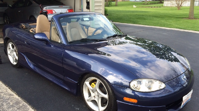
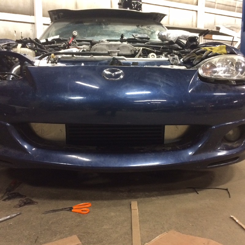
This is from the last really nice drive from last April or May of 2014. Damn do I miss driving this car. I really need to do a better job keeping it clean. It looks terrible right now.

Reply
0
0
01-18-2015, 11:43 AM
#248
Elite Member
Thread Starter
iTrader: (1)
Join Date: Feb 2008
Location: Loganville, GA
Posts: 2,331
Total Cats: 202
I spent half of yesterday pulling the motor and trans to fix my coolant reroute leak. Somehow my Teflon tape failed and I cross threaded (maybe?) the heater hose nipple.
But that's not exciting. THIS is exciting.
But that's not exciting. THIS is exciting.
Reply
0
0
01-24-2015, 07:50 PM
#249
Elite Member
Thread Starter
iTrader: (1)
Join Date: Feb 2008
Location: Loganville, GA
Posts: 2,331
Total Cats: 202
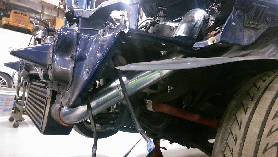
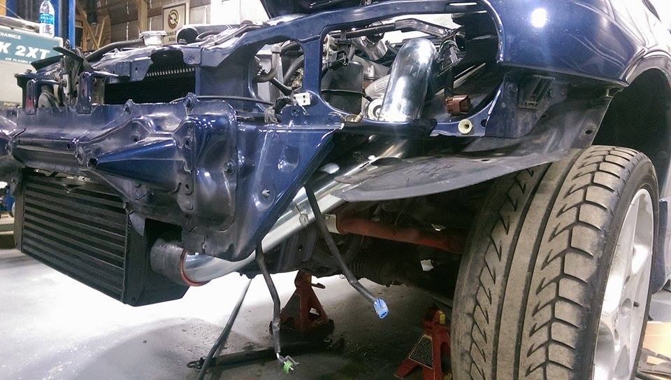
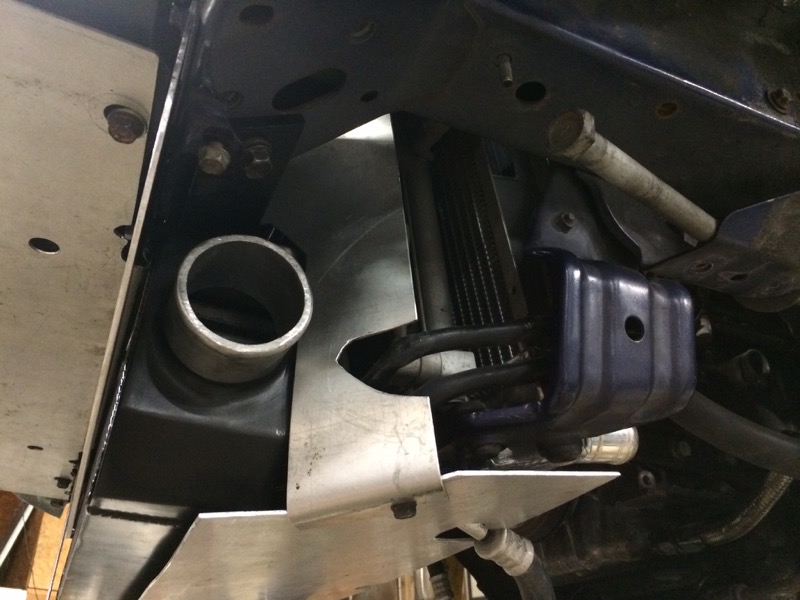
Ducting is between 70-95% done. It looked good on 1st glance yesterday but I want to look at it a bit closer before I sign off on it.
This ducting will be available for sale (with or without intercooler provision) by him based on my template, OR possibly available as a 90% kit to be modified by the user.
The air ONLY goes through the intercooler, then through the radiator/AC condenser. The air is pretty well sealed from going anywhere else. It should do a pretty good job of keeping it all cool, but we will see.
I will post more pics tomorrow but here is a quick look of where it is at from the front. Once I sign off on the design the visible parts will be painted semi-gloss black like the intercooler.
Reply
0
0
01-25-2015, 11:29 AM
#252
Cpt. Slow
iTrader: (25)
Join Date: Oct 2005
Location: Oregon City, OR
Posts: 14,192
Total Cats: 1,136
I have the same color and the current plan is to lower with Bilsteins (have) and some ebay sleeves/springs (don't have). I'm very excite because it still looks good with the stock 16" wheels. Carry on. But please don't beat my 350hp with this turbo

Reply
0
0
01-25-2015, 11:56 AM
#253
Elite Member
Thread Starter
iTrader: (1)
Join Date: Feb 2008
Location: Loganville, GA
Posts: 2,331
Total Cats: 202
On a side note, does anyone know why on some computers the images are right side up but others inverted?
Curly: Don't worry, 350hp is at minimum a year away.
Suspension changes coming soon. In the pictures it is on bilsteins with TEIN S-tech springs.
Curly: Don't worry, 350hp is at minimum a year away.
Suspension changes coming soon. In the pictures it is on bilsteins with TEIN S-tech springs.
Reply
0
0
01-29-2015, 11:06 PM
#254
Elite Member
Thread Starter
iTrader: (1)
Join Date: Feb 2008
Location: Loganville, GA
Posts: 2,331
Total Cats: 202
Big updates! Starting with the bad...
I'm not entirely thrilled with the ducting work. I feel like there is far too much of a gap for air to bypass the radiator on both sides and the bottom isn't sealed enough as well. I didn't pay much for the ducting, so I am not going to freak out about it. I don't want to take it home the way it is. I plan on having it "fixed" even if it means I have to throw a couple more bucks at them.
I'm not entirely thrilled with the ducting work. I feel like there is far too much of a gap for air to bypass the radiator on both sides and the bottom isn't sealed enough as well. I didn't pay much for the ducting, so I am not going to freak out about it. I don't want to take it home the way it is. I plan on having it "fixed" even if it means I have to throw a couple more bucks at them.
Reply
0
0
01-29-2015, 11:11 PM
#255
Elite Member
Thread Starter
iTrader: (1)
Join Date: Feb 2008
Location: Loganville, GA
Posts: 2,331
Total Cats: 202
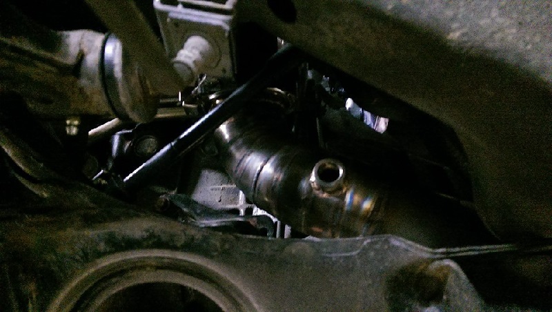
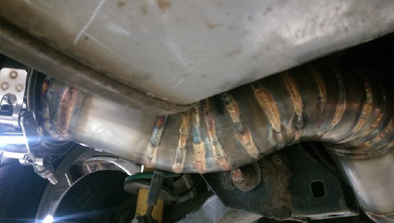
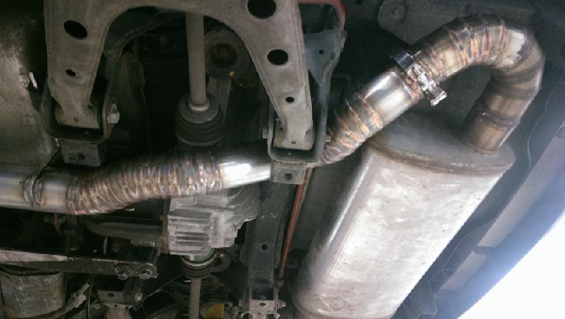
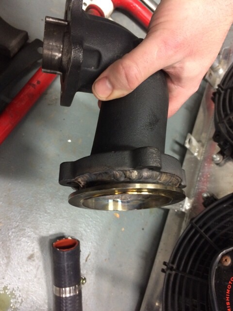
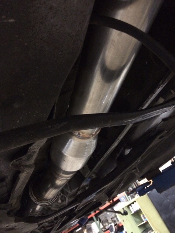
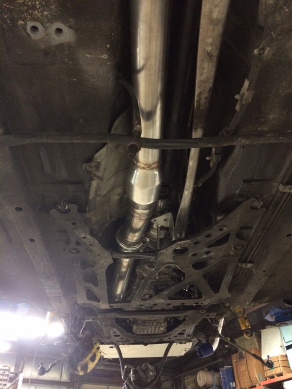
However, on a good note, the exhaust is looking freaking fantastic. The first pic is the Flying' Miata downpipe elbow with a custom V-band downpipe.
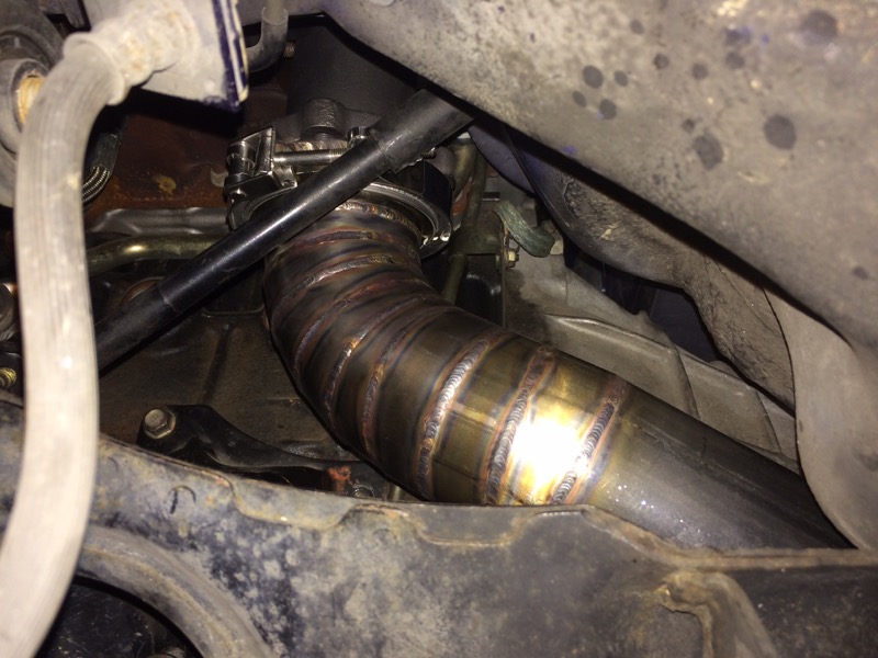
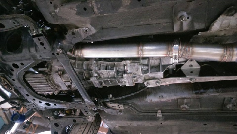
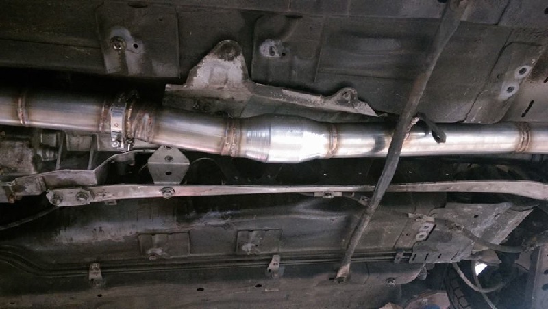
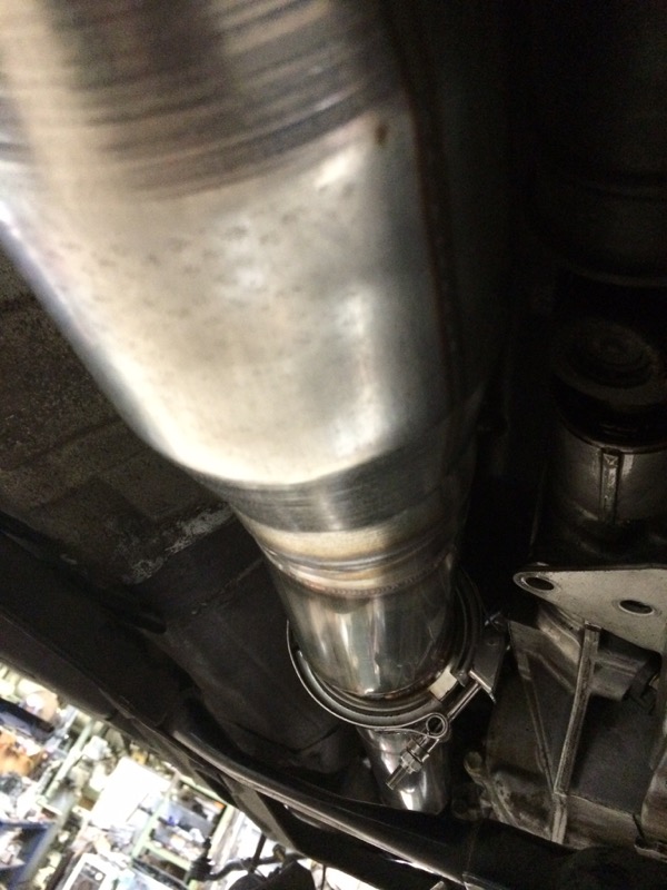
Next are some pics of the exhaust as it is as I left today. They are still working on mating the muffler to the mid pipe. I will include that picture on the next post. All exhaust is 304 stainless. Muffler is the big 3" magnaflow (p/n 12578?).
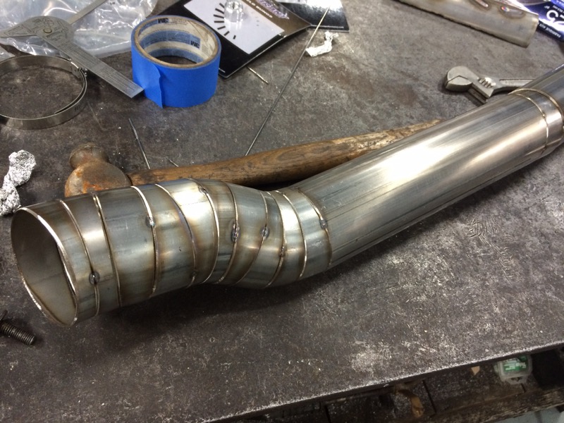
Here is the part they are working on to connect the mid pipe to the muffler. I think it's going to look pretty bad ***...
Next are some pics of the exhaust as it is as I left today. They are still working on mating the muffler to the mid pipe. I will include that picture on the next post. All exhaust is 304 stainless. Muffler is the big 3" magnaflow (p/n 12578?).
Here is the part they are working on to connect the mid pipe to the muffler. I think it's going to look pretty bad ***...
Last edited by Chiburbian; 02-03-2015 at 03:03 PM.
Reply
0
0
01-29-2015, 11:15 PM
#256
Elite Member
Thread Starter
iTrader: (1)
Join Date: Feb 2008
Location: Loganville, GA
Posts: 2,331
Total Cats: 202
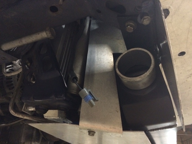
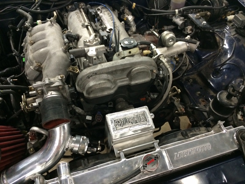
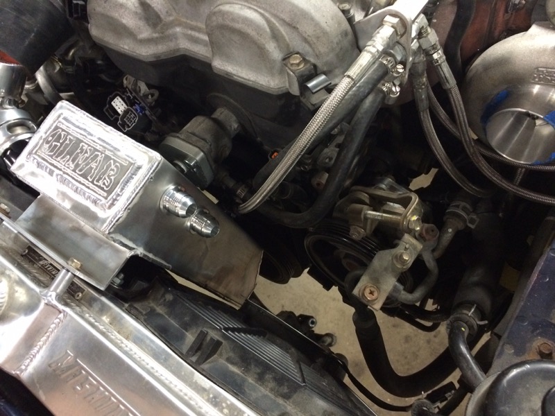
Last is my catch can...
I was talking about wanting to do a catch can and Mike convinced me to let them fabricate their own rather than buy. Plus they were able to place it in a really cool location.
It will have a drain valve or something on the bottom before it is done. I am very happy how it turned out. It will be fed by AN fittings on the valve cover.
Last edited by Chiburbian; 02-05-2015 at 11:19 AM.
Reply
0
0
02-03-2015, 01:10 PM
#258
Elite Member
Thread Starter
iTrader: (1)
Join Date: Feb 2008
Location: Loganville, GA
Posts: 2,331
Total Cats: 202
I talked to Mike the fabricator yesterday and learned I was mistaken about the ducting. There are in fact side pieces that will go there and seal it up, but I don't doubt that there will be some fine tuning that will require tape or something else to seal up the last 10% as you say.
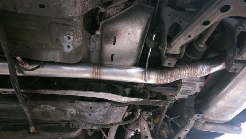
I have some pics of the rear of the mid-pipe that I should be posting later tonight.
I have some pics of the rear of the mid-pipe that I should be posting later tonight.
Reply
0
0