When you click on links to various merchants on this site and make a purchase, this can result in this site earning a commission. Affiliate programs and affiliations include, but are not limited to, the eBay Partner Network.
I first purchased this 2001 NB2 Miata in October 2017, and for the most part simply enjoyed it for the better part of a year, making plans, revising those plans and reading oh so much, unsurprisingly most of my reading was through miataturbo.net.
My modifications started as most street cars do, with a semi-decent stereo, and so it stayed for the better part of that year.
Toward the end of 2018, I placed my order with DIY for a MSPNP Pro, MAC valve, Innovate LC1 and assorted bits and pieces, as stage 1 of my build.
I installed the MSPNP with little fuss, welded an extra bung into the stock exhaust for the Wideband, as at that stage I wanted to be able to go back to stock if things didn�t turn out well, and then set about the fun of learn to tune. Granted at the start I was happy as the base tune was good enough to start and run the car, but I quickly found that the idle settings would need a lot of work as it would often dip and stall, over the following months I ironed out the idle settings and started enjoying the car again and the freedom that MS would give me.
At this stage I decided that given that I have 2 E85 stations within 5 miles of my house, that it would be a good time to get a flex sensor and wire/tune the MS for flex, although I honestly had intended to run E85 almost 100% of the time, but I wanted flex mainly for the long road trips I take a few times a year.
I know some people have had trouble with the quick connect fittings (the push on one�s vs the screw on one�s) but for the 6 months that I had them on no fuel smell or leaks of any kind.
I manage to get 115hp out of it at this stage.
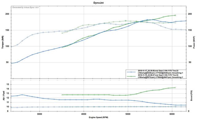
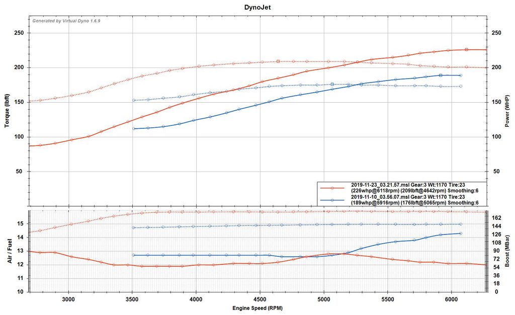
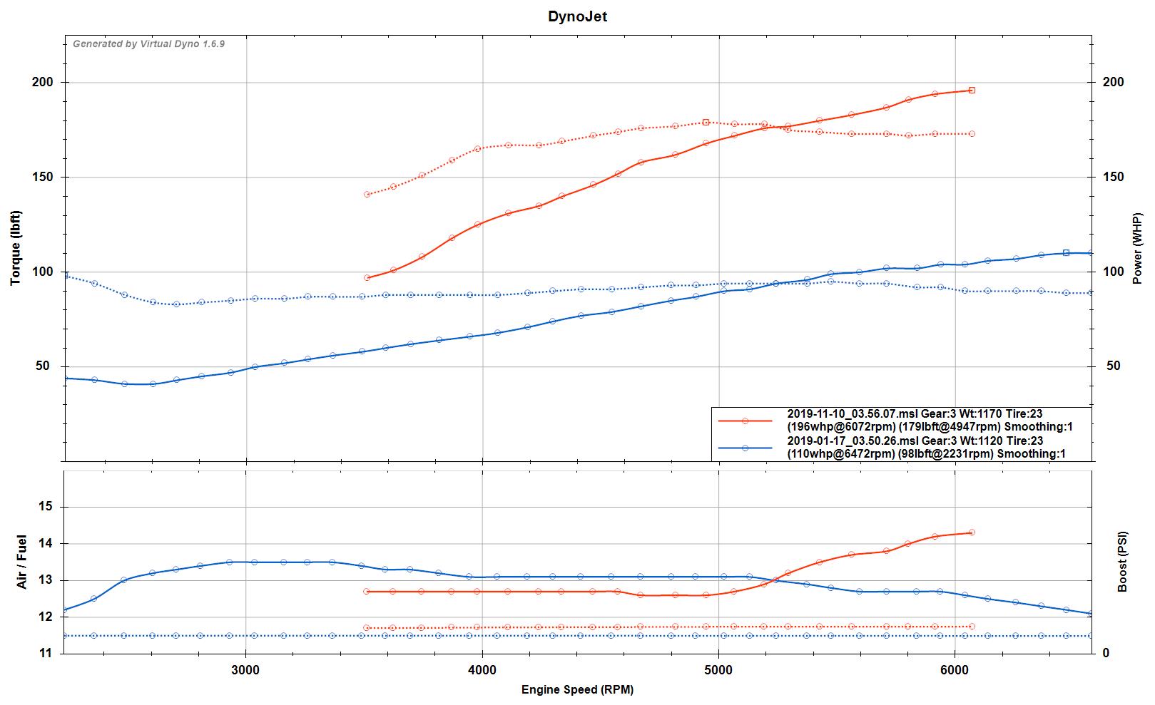
I didn�t get an VD runs done on the original tune, but I have some once I was on E85. Here it is with a comparison to the current turbo build.
I have officially found the limit of the stock purple 265cc injectors, at 60psi idle, and 6psi boost, I am leaning out to 14.5 at 6000 rpm. Naturally, I won�t be doing any more pulls like this until I get my new injectors, I�ve decided to go with 1050Xs as it seems I may have issue with idle quality with the 1700X. Once I get the 1050X in it�ll be time to turn up the boost.
I've also attached the log that goes with this VD run, so you can see what I mean when I say its leaning out above 5k rpm.
Then as fate would have it I lost my license from May 1st to Nov 1st this year (2019). So I figured that this would be the best time for stage 2 of my modifications. Which involved a whole bunch of parts and while I haven�t added everything up, I�m sure that I wouldn�t have much change out of $10k.
Parts list;
1. Radium fuel rail
2. DW300
3. 5m pushlok AN8 hose
4. 5m Series 200 nylon braided AN8 hose
5. Assorted multiple fittings to suit both hose types.
6. Turbosmart FPR2000
7. Assorted stainless hardware (Bolts, P-Clamps etc.)
8. Full AVO Turbo kit (GT2560R based w/ intercooler etc.)
9. ID1700X Injectors (Changed to 1050X awaiting delivery)
To skip forward a bit, I kind regret the AVO kit for a few reasons, while I did enquire with both TSE and MK for their turbo kits (More on why I�m disappointed I couldn�t get the TSE kit in a bit), they both said that they do not and would not ship internationally, and while I don�t blame them given the pain in the *** it can be, I really wanted the TSE kit with 7163.
I�m sure I�ll be happy for the moment with the GT2560 but long term I�m looking for a lot more than it can give, but I guess that will be stage 3 along with a rebuild.
I didn't purchase the injectors to begin with as I want to see what I can do with the stock injectors, also it�s one less thing to worry about as I start to tune above 102 kpa.
The fuel system wasn�t too much trouble to upgrade to AN8, although I think that that is about as large as you can go without dropping the tank to run the lines, as while it wasn�t too hard to get the AN8 lines in place, the pushlok especially was a pain.
I used the braided lines for the pressure side of things and the pushlok for the return. Right now I am using a 30um filter, although I�m considering going with the ID F750, depending on how things work out.
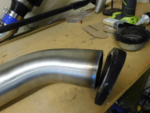
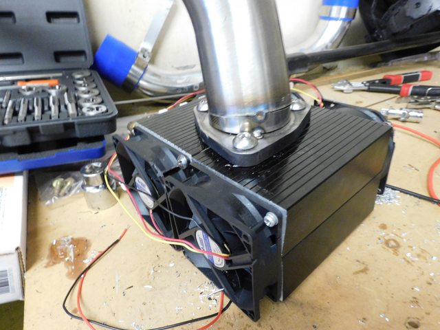
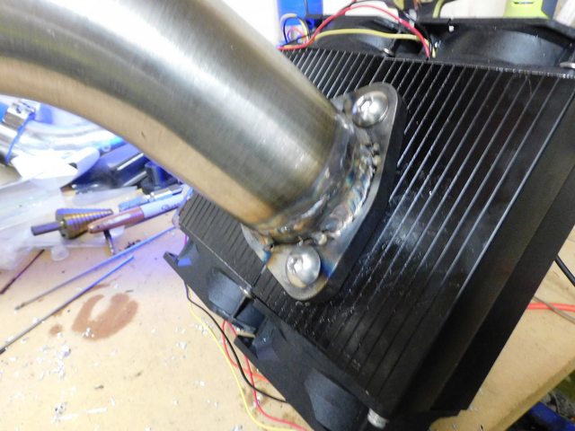
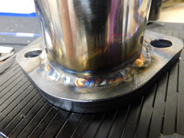
Now, I did have a few issues with the AVO kit, most serious of which was the included downpipe. The issue that I had with it was the angle of the turbo side flange, due to that angle that it was welded on, I would have had to of bashed in the floor pan to make it fit, and even if I did go that route, I felt that the heat from it would need mitigating, so I cut off the flange and using decent aluminium tape, and a tack weld, found the angle that would work, this happened to be 12.4 degrees. I then cut out a sliver of 2.5� stainless tube and welded it on, thus giving me the correct flange angle. For the welding I decided to give a heatsink a try on the flange, as I was worried about the flange warping, so I used a 6.5� square aluminium heatsink that I affixed 4 pc case style fans too, along with my portable benchtop power supply, the fans are generic things although at 40cfm each they do the job nicely. I actually originally used this heatsink with a Peltier module, still affixed to one side. And it looks like the heatsink did its job, even though I�m not the best at welding, it worked out in the end.
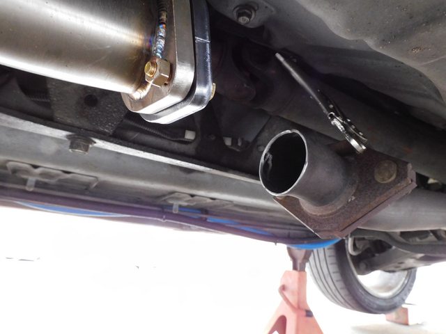
This then caused the muffler side flange to be almost 90⁰ with the bolts at the top and bottom, which leads to the second issue with the down pipe. I believe it was designed around an earlier NB platform, with a separate cat pipe, rather than the NB2 version that has the cat in the secondary header pipe.
Faced with this, I had to options, extend the downpipe like stock so that it would mate up to the rest of the exhaust like stock, or add a cat/test pipe. Given that shortly I will be going to a 3� system, I figured I would just add the test pipe for now, as I thought it would be easier to manoeuvre things like that, as sadly I am yet to buy a hoist (Another future investment J)
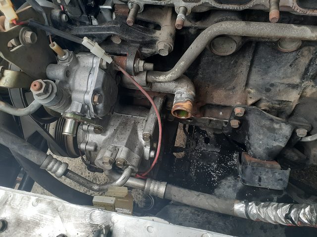
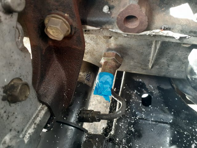
Drilling the oil return was nerve racking to say the least as I have never drilled into an oil pan before let alone on that is still on the engine and in the car. I used every trick I had read about to help ensure that things went smoothly, including hooking up a compressor to the valve cover and running about 5psi through it, as well as copious amounts of grease. I was surprised how well the compressor worked at such low pressure, I had chips flying around all over me, which I think is a good sign.
First start after the install was rather nerve racking, as I have never drilled an oil return with the sump pan still on the engine, I started off with trying to build pressure with only the starter, which sadly didn�t give any results, mainly I think because of the fake nature of the stock NB oil pressure gauge/sensor. So I crossed my fingers and started her up, to both my amazement and relief it started as fast as it did before all the work, and within 2-3 seconds I had my oil pressure, no strange noises or other signs of problems.
So I let her warm up, burped the coolant and set ab out checking for leaks. Sure enough, the heater hoses where leaking, mainly I think because I re-used the stock spring clamps, so a swapped them out for some T-Clamps, but the ones I had bought were too big L, so I used standard worm clamps, they solved the leak, thankfully that was the only leak I had, no oil leaks at all.
So I have fuel pressure set at 60psi at idle, and waste gate only right now, running about 6.5psi. Have to get that EBC setup, after I finish tuning the fuel. So far I am at or around 90% DC which isn�t bad considering that I was at around 87% on E85 non-turbo with the stock return-less system.
Sadly, the BOV that was included in the kit was a generic denso model, and unfortunately it doesn�t seem to be working that well, although it doesn�t leak or anything as bad as that, it does seem to be completely useless, as I am getting that sound of what I believe to be surge, that Choo Choo Choo, and while I�m sure there are those that actually like that sound, and I personally find it amusing at times, I really don�t want the attention that it will cause.
So that that end, I am getting a Turbosmart Kompact to replace it, thankfully it also uses a 20mm barb attachment method, as does the denso, so at least it should be a bolt on affair.
So far I am at around 195hp according to VD. I�m not sure how that stacks up, but given where I was (115-120hp) I think its decent on 6 psi. Once things are settled down, I�ll get around to doing some runs on a dyno.
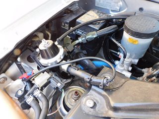
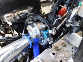
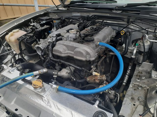
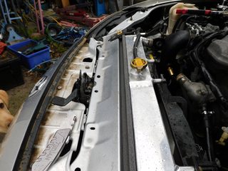
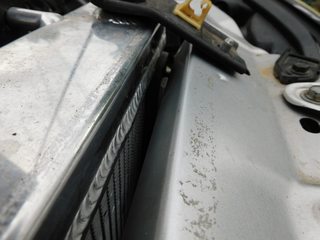
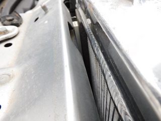
While I was doing the turbo install and had the most space I have ever had in the miata engine bay, with the radiator and such out of the way, I figured i would seal up all the gaps that I could, mainly between the radiator and a/c condenser, I still have to seal the intercooler against the condenser, but so far my temps have been rather good.
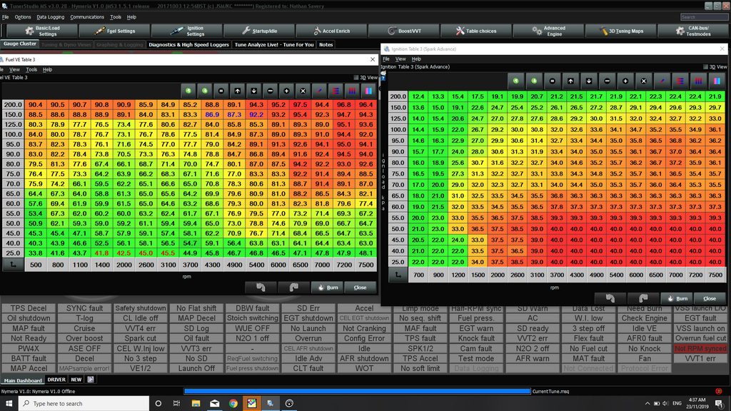
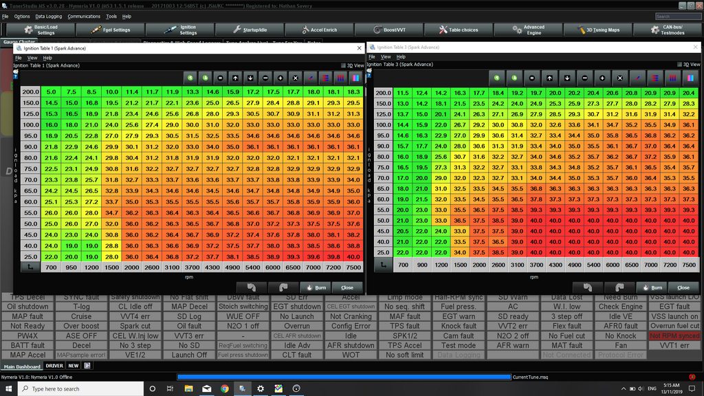
I am curious to get peoples opinion on my timing map also.
There is no knock or anything like that, however, given the maps that I have seen from others here, it would seem that mine is rather aggressive, unless I'm missing something (Perhaps in different MS/TS versions)
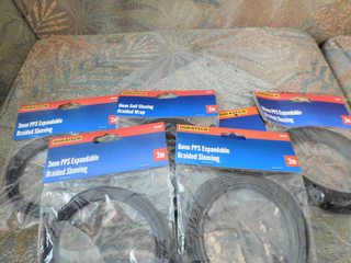
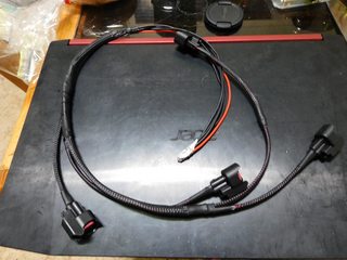
So after the issue of running out of injector, I bought some 1050X for ID, and built a new injector harness, along with wrapping all the associated wiring in the area (I.E temp sensor, ground harness and the condenser/capacitor)
Wiring supplies
Part way into the harness
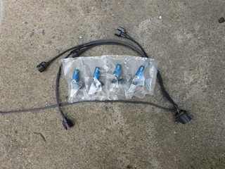
Completed harness and injectors
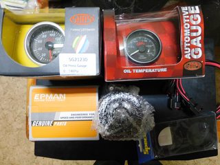
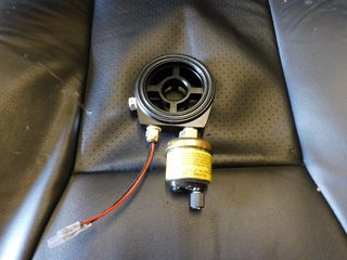
So, at the same time that I ordered the 1050x, I figured I would need USCAR/EV6 connectors, so I ordered them from an Australian ebay seller and figure while I was at it, I would also get a Oil temp and Oil Pressure sensor as well as a sandwich plate.
Little did I know ID would ship connectors with their injectors.
So, after installing the injectors, I'm thinking that I have a minor vacuum leak, mainly because I finally decided to try and get my idle solid under 1k rpm, as I have normally been idling at around 1000-1020 since installing the MS.
I don't think that I pinched or damaged the injector Orings as the vacuum I get at idle is still the same as I got prior to the install, at around 30kpa going up to approximately 32 with the fans going.
So, either way I order a full intake side gasket set with the 3 gaskets, as well as a full new set of Orings for the IDs just incase.
After installing the IDs and re-setting the required settings, I got out and tuned them in, surprisingly, the low end outside of boost had very little change, in boost though, I need to take out a lot of fuel, obviously because I was running out of injector, the VE table was massively out.
This was my first full throttle run, log attached.
As you can see it is we too rich, but at least it shows that I will have plenty of fuel for the fun too come.
If anyone can give advice, I am targeting 12.5-12.6 at 150kpa on E85, does this sound reasonable?
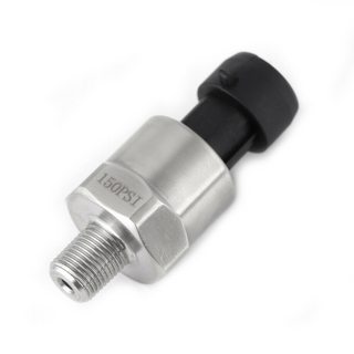
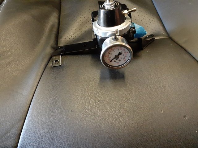
After reading about this type of pressure sensor here, I decided to get one to investigate and see if they�re worth using. I decided to buy a 150psi version because that would cover almost all pressure levels that I would need, without losing too much resolution. I decided to install it on the FPR2000. Attached it to the analogue 1 input of the MS and set the generic sensor input to the correct settings for this sensor.
A little bit of calculation is needed because the sensors are defined as 0.5vdc min and 4.5vdc max, were as the MS is 0vdc Min and 5vdc Max, I just got the psi/v and used that to calculate the required values. Turns out that they work rather well.
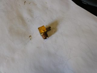
After getting the fueling reasonable I decided to install the MAC valve, strangely at least to me, the IWG has a 6mm vacuum port, about they installed a 4mm port on the turbo, which I promptly broke trying to tighten a 6mm silicone hose onto it, so I replaced it with the correct part, and set about tuning open loop boost control.
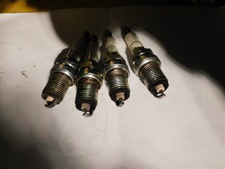
I ended up with 40% dc, which gave me 12psi, granted this did vary over the next few days, as I do all of my tuning in the middle of the night, which also results in single digit to low teens (C⁰) air intake temps. At this boost level, I started to get spark breakup, I believe due to using BKR6E-11, which have a standard gap of 1.1mm or 43thou. I change them out for some BKR7E, which were gapped at 0.8mm or 32thou, this solved the problem of spark blowout.
All the sparkplugs looked good, at least to me, when they came out.
During the days when the air temp was slightly higher I would see around 8-9 psi. I am eager to both turn up the boost more and tune closed loop to avoid the issue of varying boost levels. But with around 200 ft.lb and 225ish hp, I�m not sure how much more my poor stock rods can handle. Having said that I�m surprised my clutch is doing as well as it is.
Here is my current fuel and ignition maps for those that are interested.
I briefly was able to get the denso BOV to work, by moving the vacuum port, my mistake was using the wrong port on the IM, it worked for 1 decent tuning session but has stopped working once more, now I�m wondering if its due to the placement of the current Vacuum port at the front of the IM just behind the TB or if it�s the line sizing (currently 4mm), next up will be trying a 6mm line to the back of the IM, if this doesn�t work then it�ll be time for a Turbosmart BOV.
12.5 AFR on pump gas equates to 8.3 AFR on real E85 which is .85 lambda. Stoich for pump gas s 14.7:1 and 9.8:1 for E85. Lambda is a better number to watch and use because it �normalizes� the calculation based on whatever mixture you end up getting at the station. My target is 0.85 lambda at 160 kpa.
Your calcs are 12.5/14.7 = 8.3/9.8 = 0.85 lambda. 12.5:1 on E85 is NOT GOOD! 12.5:1 on pump gas is good.
It appears that gauges show AFR as though it were E0, even with E85.
Last edited by Turbomack; 11-25-2019 at 09:07 AM.
Reason: Appears there is some backwards math with gauges that shows AFR as though it were E0.
12.5 AFR on pump gas equates to 8.3 AFR on real E85 which is .85 lambda. Stoich for pump gas s 14.7:1 and 9.8:1 for E85. Lambda is a better number to watch and use because it �normalizes� the calculation based on whatever mixture you end up getting at the station. My target is 0.85 lambda at 160 kpa.
Your calcs are 12.5/14.7 = 8.3/9.8 = 0.85 lambda. 12.5:1 on E85 is NOT GOOD! 12.5:1 on pump gas is good.
The sensor reads in lambda and converts to gasoline AFR. The sensor doesn't know you switched fuels. It just assumes you're using gasoline. What this ends up meaning is that 1.00 lambda is always going to be displayed as 14.7. 12.5 AFR displayed on the gauge is always going to mean 0.85 lambda.
TLDR: 12.5 AFR displayed on the gauge when using E85 is totally fine.
Thanks Spartan. I edited my post but still baffled as to why gauges assume you are on gasoline all the time. My ECU logs lambda, reports lambda and uses a lambda table for tuning which makes the most sense to me using a flex fuel sensor.
You are both correct.
I could update the configuration in the LC2 with the serial adapter and Innovates calibration software to show E85 AFR, however with flex it is best, in my opinion to remain with gasoline for the sake of simplicity.
In the end as you said, the AFR reading on the gauge and indeed even in TS is only a calculation based on Lambda, thus it really doesn't matter as long as you take it into account, I.E base everything on the same calculation.
Well its been quite some time since I last updated this.
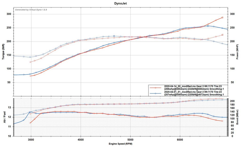
For about 6 months I thoroughly enjoyed the car, VD indicated around 275hp, always done on the same road, and normally averaged between both directions.
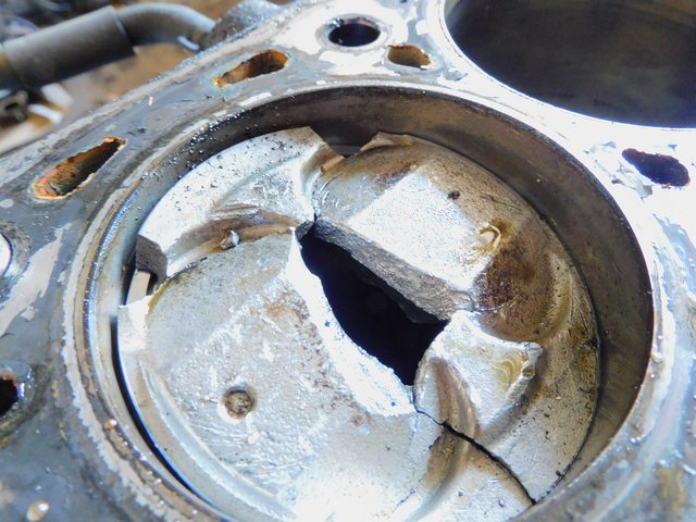
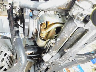
Sadly, in May 2020 she released the magic smoke, and ventilated the block.
After buying a new car, and not being in the mood to deal with it for the better part of a year, I have decided to start looking for a replacement engine, naturally building it to some degree this time to avoid this happening again in the immediate future.
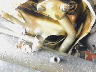
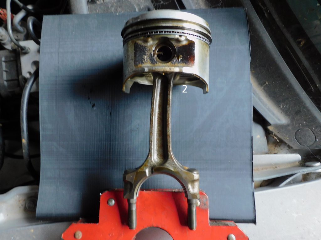
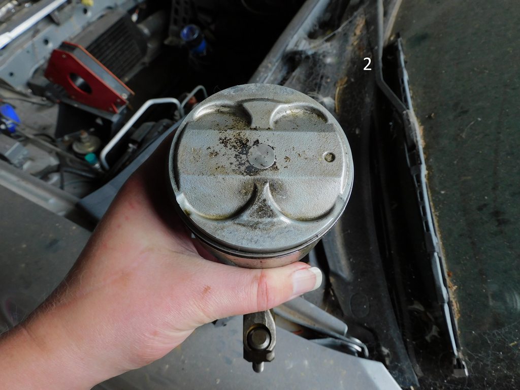
I believe that I may have floated a valve, number 1 on cylinder 1, markings on the piston and the broken valve head in the chamber help me support this conclusion.
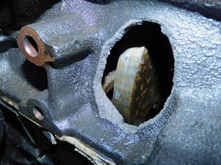
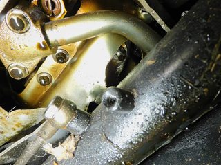
So it seems that once the piston hit the valve, snapping it, the rod then let go and started poking holes in the block.
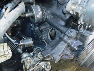
Thankfully the turbo seems ok, along with most other things that aren't in the bottom end.
I should take some better photos, but to my untrained eye, I can't see any detonation on the intact pistons.
If anyone else has some theories as to the mode of destruction, I would love to hear them.
So, I guess this is a cautionary tale about the need for better valve springs when boosting.
This happened on a run at 17ish PSI.
It was also on an unopened bottom end.
I was logging at the time, so I'll post my logs and tune when I get home later today.
So the plan now is to try and find a replacement VVT engine, throw some rods and valve springs at it, along with the necessary bearings etc. a genuine gt2560 should be ok with just those, shouldn't it?
This is a VD graph from the weeks before it happened;
Last edited by pyr0boy; 04-15-2021 at 01:50 PM.
Reason: Added VD Graph
If you floated a valve and it made contact with a piston it would have likely just bent the valve and dinged the piston. Even that's extremely unlikely as the BP is a non-interference engine.
My theory is the rod let go and the untethered piston smashed into the head.
Lots of people have pushed stock valve springs harder than you. Myself included.
Before I tore it down, I thought the same to be honest. I knew that the rods were on the edge of safety.
In your opinion, what would have snapped the head of the valve? If the rod went first, and the piston then hit the valve, wouldn't the valve still only bend?
Valve fully open with the piston's travel limited only by the head itself. That's very different than the piston making it's usual movement and grazing a valve that's floating open.
I also really doubt you could have floated a valve so hard that it hit a piston. The BP is a non-interference engine which means when the pistons are at the top of their stroke and a valve is fully open they won't make contact. You would have to push the valve to a point of lift beyond what the camshaft can. I don't see that happening.
I really didn't think the piston would have more energy, enough to snap a valve, after being disconnected from the rod.
But you very well may be right.
I might try and measure the spring pressure of the valve spring in question, if I can work out a nice easy DIY way to do it.
While you might be right, maybe the valve spring wasn't up to spec.
Would a rods+springs only build be enough for maxing out a gt2560, what ever that gets me?
Here is the tune and log of the time this happened.
Also PNG for those that don't have access to Megalog.
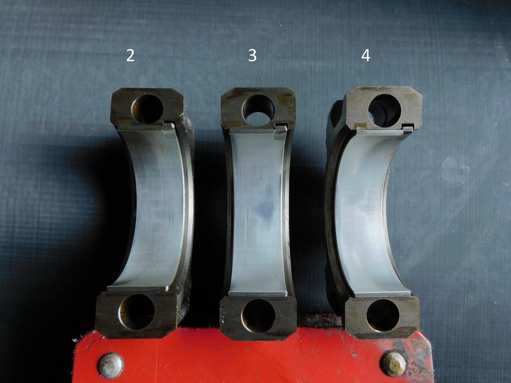
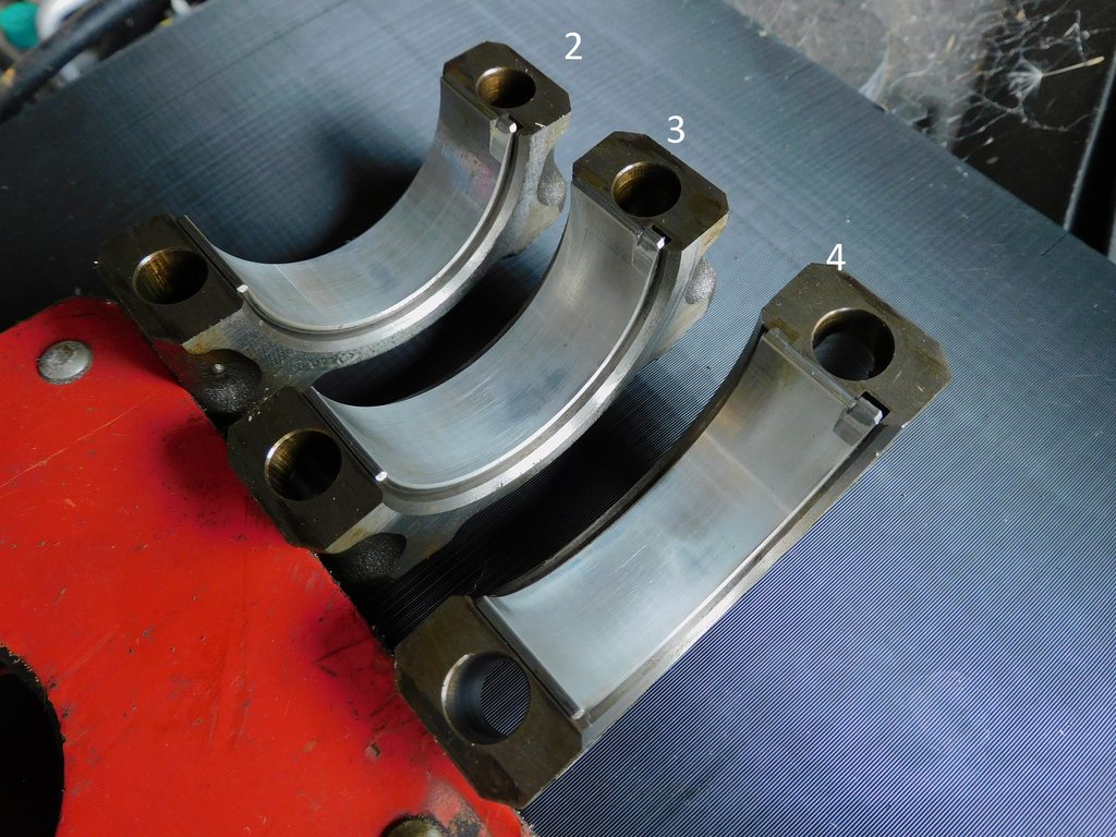
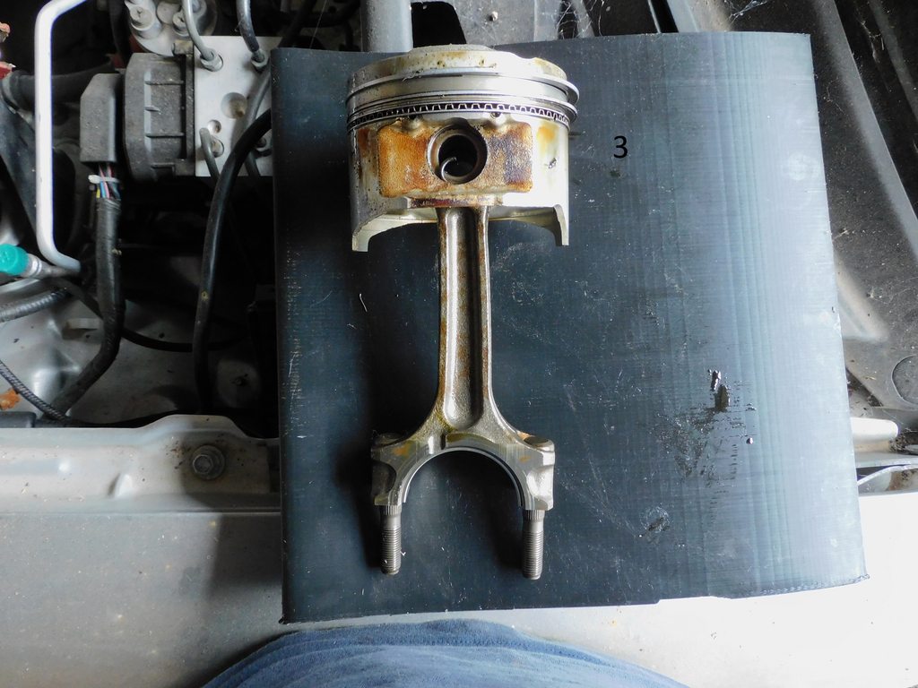
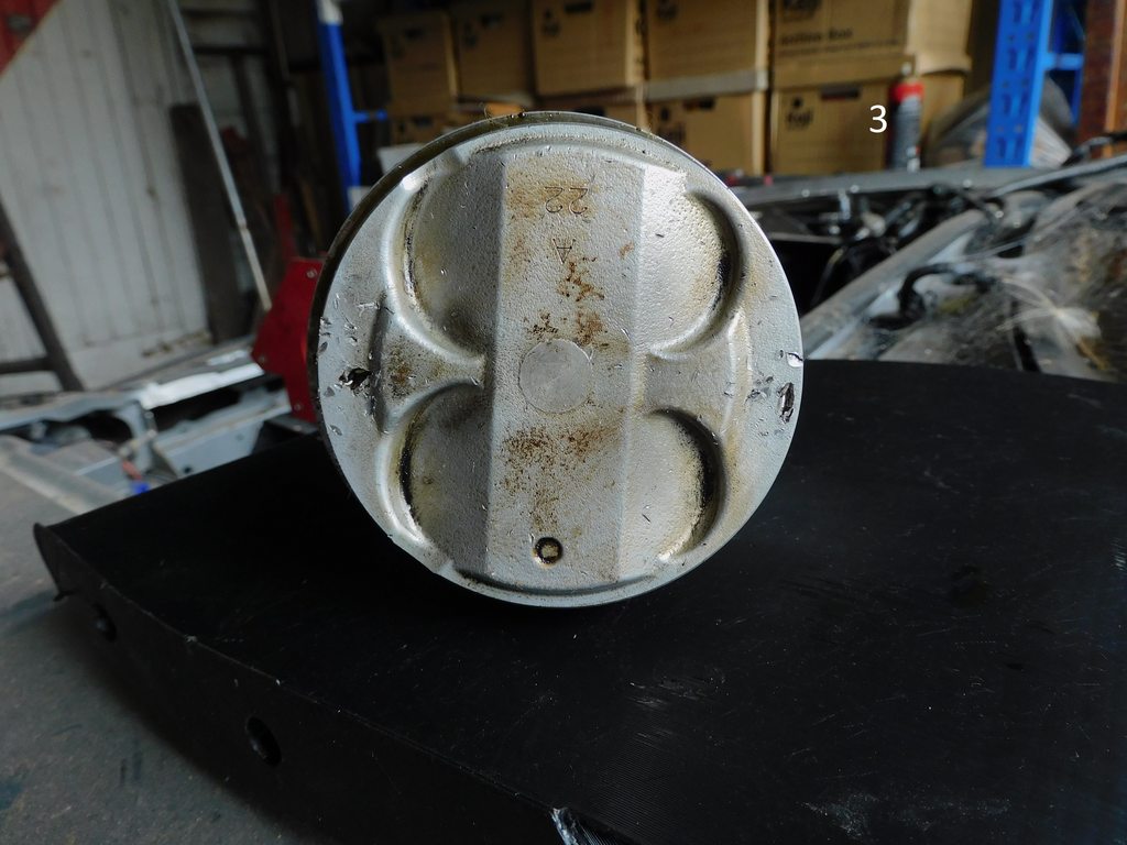
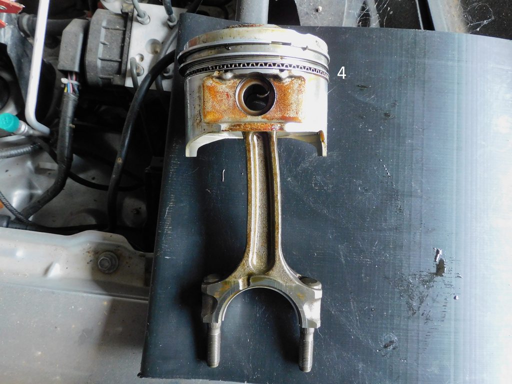
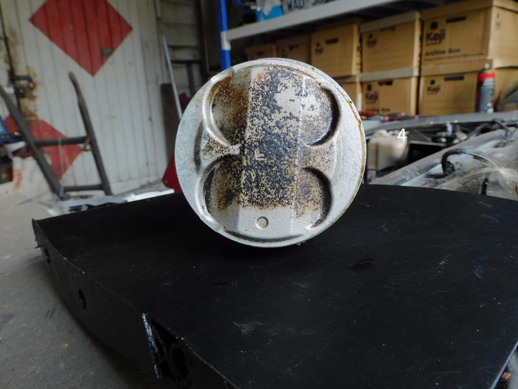
So, I just pulled the remaining 3 pistons to see how the 2-3-4 rods look like.
Sure enough, as I'm sure most would expect they aren't exactly straight.
I'm still convinced that there was no detonation, there are a few dings from things bouncing around inside, but that's limited to piston 3.
The rod bearings also look reasonable for the hell the went through at the end.
So if number 1 rod decided to evacuate under the pressure of my right foot, was it only due to the power, or is there something else at play that I haven't thought of?
AFR and timing are fine for e85. I agree there was no detonation. 16 psi from a 2560 with E85 would put your torque numbers well in to the danger zone. Add the cool temp that day and it was game over.
I went rods only with a NA8 head and totally maxed a 2560. You can do springs if it makes you feel warm and fuzzy, but it wasn't valve float that killed this thing.
 11-12-2019, 01:25 PM


 0
0