M90 out, MP90 going in
 08-28-2011, 01:02 PM
#1
Junior Member
Thread Starter

Join Date: May 2007
Location: Toronto Area, Ontario
Posts: 327
Total Cats: 95
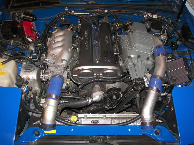
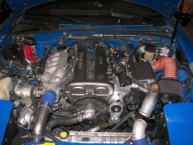
Perhaps, a few will find this supercharger install interesting...
Current engine setup:
M90 supercharger from 95 Thunderbird, with a 2000 GM M90 rotor pack.
Ignition is dual MSD 6A’s driving stock 90 coils.
Throttle body is a LS1 2 x 48mm
A Chrysler Conquest intercooler, recently swapped to a Fleebay unit.
Custom MS1 (different pcb, with better grounding, and circuitry to drive MSD’s, water injection, DC IAC circuit, plus a few other outputs.)
A dual throttle body & blow off valve combo.
Rods, oil pump, fuel mods etc. etc.
Here is a pic.
This set up yields decent power, and I wasn’t planning on changing anything this year, until about 3 months ago, when I noticed that Roush was blowing out their MP90 superchargers, designed for the Mustang, for $350 shipped. I suspected the M90 was killing my high RPM power, so I had to order one…
Here is the progress I have made over the last ~3 months on this build.
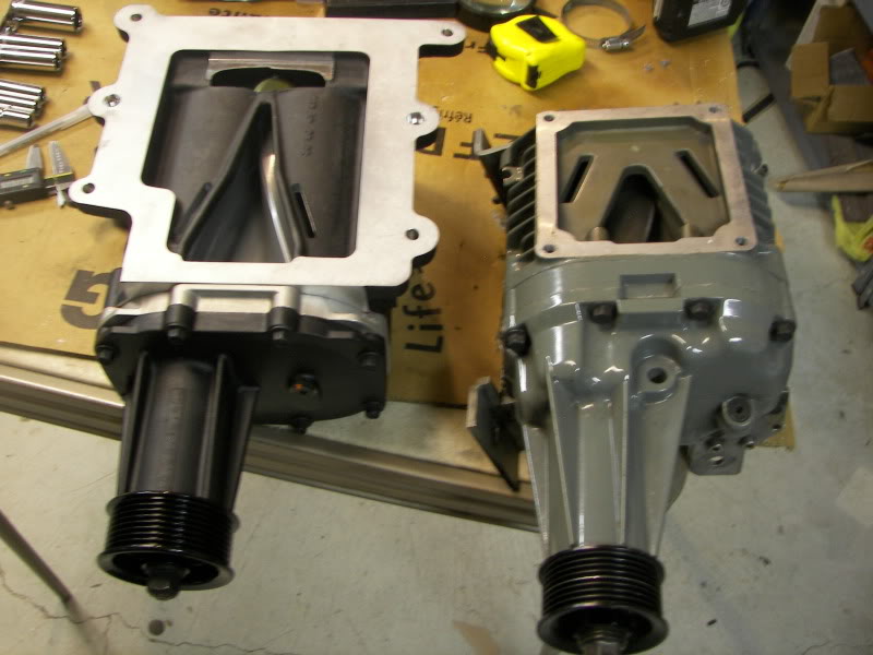
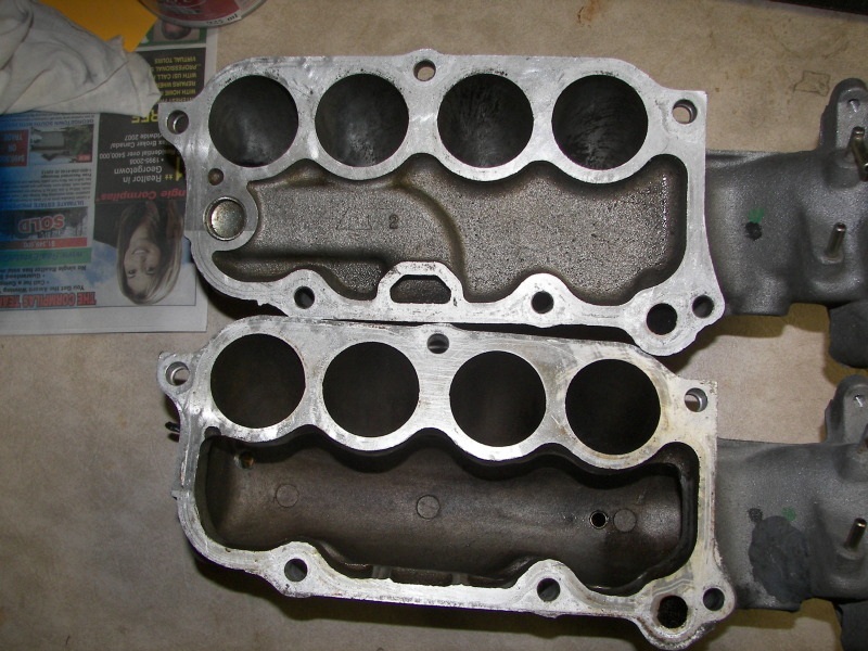
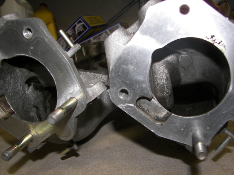
Here are some comparison pics, of the MP90 to the M90. The SC body is larger, but the drive is shorter than the one I currently have.
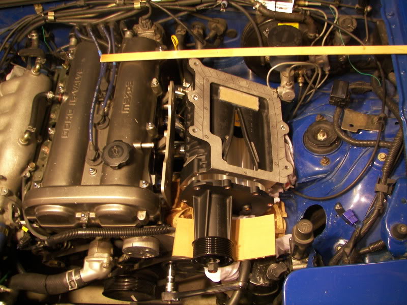
Here is how it looks in the engine bay.
Current engine setup:
M90 supercharger from 95 Thunderbird, with a 2000 GM M90 rotor pack.
Ignition is dual MSD 6A’s driving stock 90 coils.
Throttle body is a LS1 2 x 48mm
A Chrysler Conquest intercooler, recently swapped to a Fleebay unit.
Custom MS1 (different pcb, with better grounding, and circuitry to drive MSD’s, water injection, DC IAC circuit, plus a few other outputs.)
A dual throttle body & blow off valve combo.
Rods, oil pump, fuel mods etc. etc.
Here is a pic.
This set up yields decent power, and I wasn’t planning on changing anything this year, until about 3 months ago, when I noticed that Roush was blowing out their MP90 superchargers, designed for the Mustang, for $350 shipped. I suspected the M90 was killing my high RPM power, so I had to order one…
Here is the progress I have made over the last ~3 months on this build.
Here are some comparison pics, of the MP90 to the M90. The SC body is larger, but the drive is shorter than the one I currently have.
Here is how it looks in the engine bay.

Reply
 0
0

0
08-28-2011, 01:05 PM
#2
Junior Member
Thread Starter
Join Date: May 2007
Location: Toronto Area, Ontario
Posts: 327
Total Cats: 95
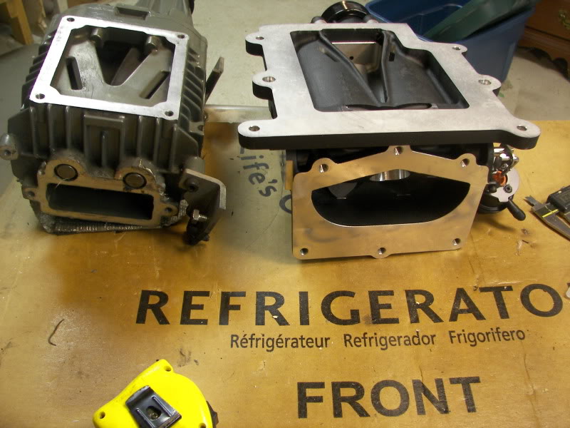
The first step, was to machine the casing of the supercharger, trimming off the extra flange material on the top and rear. Then, in order to provide as much room at the rear of the supercharger as possible (for throttle body and intake pipe), I procured a short snout drive shaft, machined the snout, and then fitted a dual race bearing, rather than 2 individual bearings. Here is the result.
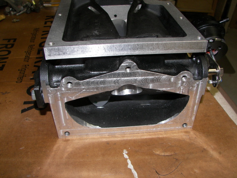
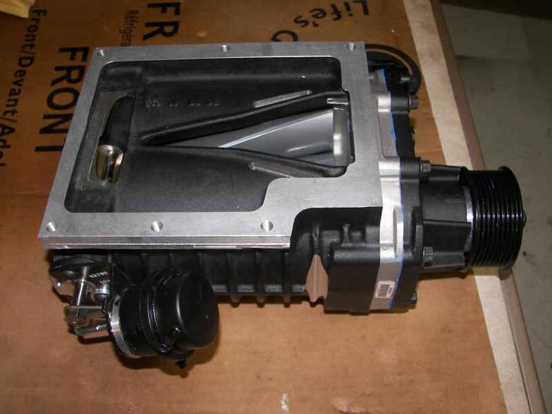
The next step was the mounting system for the supercharger. Rather than build everything from scratch, I managed to procure a BRP plate from a local club member. I then made the 3 aluminum pieces shown below, as well as the lower strut support, which I will replace with a fixed length aluminum bar, once I have finalized everything.
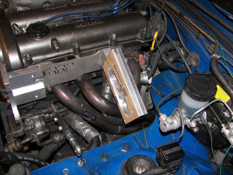
The next step was the mounting system for the supercharger. Rather than build everything from scratch, I managed to procure a BRP plate from a local club member. I then made the 3 aluminum pieces shown below, as well as the lower strut support, which I will replace with a fixed length aluminum bar, once I have finalized everything.
Reply
0
0
 08-28-2011, 01:16 PM
#4
Junior Member
Thread Starter
Join Date: May 2007
Location: Toronto Area, Ontario
Posts: 327
Total Cats: 95
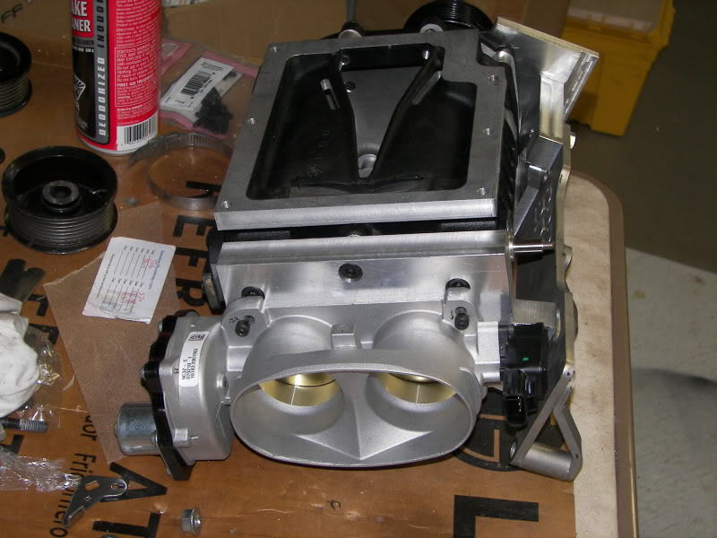
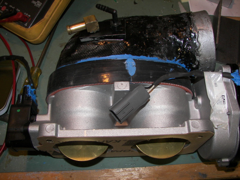
On my M90 set up, I am using a dual bore throttle body. This was used because the inlet to the supercharger is wide but not tall. To adapt a large bore single throttle body to this inlet, is a bit of a problem, especially with the limited space. This time around, I wanted to use the same basic thing, only change to electronic control, and of course go a bit larger.
After a bit of research, I found I could order a Mustang SVT 2x60mm throttle body, from my local SVT Ford dealer for $150, plus $10 shipping. Quite a deal, considering it’s thru the dealer. (they quoted me $76 for the gasket, so I ended up making my own)
Here is the supercharger with the throttle body attached.
Next step was to build the throttle body inlet pipe. One disadvantage to using the 2x60mm throttle body, is the odd shape inlet. Like my M90, I decided to build a inlet using an epoxy/fiberglass material, using a styrofoam SM mold. Here is the process I used.
Shape the object, using first a sharp knife, and then sandpaper. (sandpaper cuts thru Styrofoam pretty quick, so you can do this fairly quickly)
Coat sections that require it, with drywall compound and sand smooth.
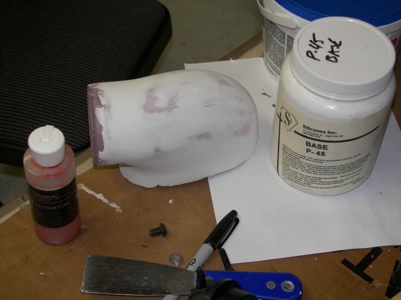
Coat the part with gelcoat, or a similar mold release material. I used a silicone material for this, which turned out to be well past it’s prime. It didn’t harden properly.
Now build up layers of fiberglass/epoxy over the mold release material. When that’s complete, pour a bit of lacquer thinner onto the styrofoam. This will melt it. Remove the liquid, making sure you don’t get any on your part, since it’s hard to remove. If you’ve done things properly, the inside will be very smooth, while the outside will look like hell. My results on this piece, were not steller, due to the issue with the silicone gelcoat.
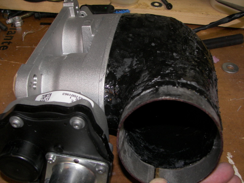
Next, got some silicone hose, cut and spliced pieces to required length. Used a couple of layers of fiberglass to strengthen it.
I find that Permatex Ultra blue silicone, is great stuff.
Nearly complete part on the throttle body...
After a bit of research, I found I could order a Mustang SVT 2x60mm throttle body, from my local SVT Ford dealer for $150, plus $10 shipping. Quite a deal, considering it’s thru the dealer. (they quoted me $76 for the gasket, so I ended up making my own)
Here is the supercharger with the throttle body attached.
Next step was to build the throttle body inlet pipe. One disadvantage to using the 2x60mm throttle body, is the odd shape inlet. Like my M90, I decided to build a inlet using an epoxy/fiberglass material, using a styrofoam SM mold. Here is the process I used.
Shape the object, using first a sharp knife, and then sandpaper. (sandpaper cuts thru Styrofoam pretty quick, so you can do this fairly quickly)
Coat sections that require it, with drywall compound and sand smooth.
Coat the part with gelcoat, or a similar mold release material. I used a silicone material for this, which turned out to be well past it’s prime. It didn’t harden properly.
Now build up layers of fiberglass/epoxy over the mold release material. When that’s complete, pour a bit of lacquer thinner onto the styrofoam. This will melt it. Remove the liquid, making sure you don’t get any on your part, since it’s hard to remove. If you’ve done things properly, the inside will be very smooth, while the outside will look like hell. My results on this piece, were not steller, due to the issue with the silicone gelcoat.
Next, got some silicone hose, cut and spliced pieces to required length. Used a couple of layers of fiberglass to strengthen it.
I find that Permatex Ultra blue silicone, is great stuff.
Nearly complete part on the throttle body...
Reply
1
1
08-28-2011, 01:32 PM
#5
Junior Member
Thread Starter
Join Date: May 2007
Location: Toronto Area, Ontario
Posts: 327
Total Cats: 95
I am currently working on the belt tensioner, the wiring for the throttle body controller, and the SC outlet to the intercooler.
Here is how it currently looks, with these parts tacked in place. It's a bit tight, around the SC outlet. I'm probably going to be taking a hammer to the tubing....
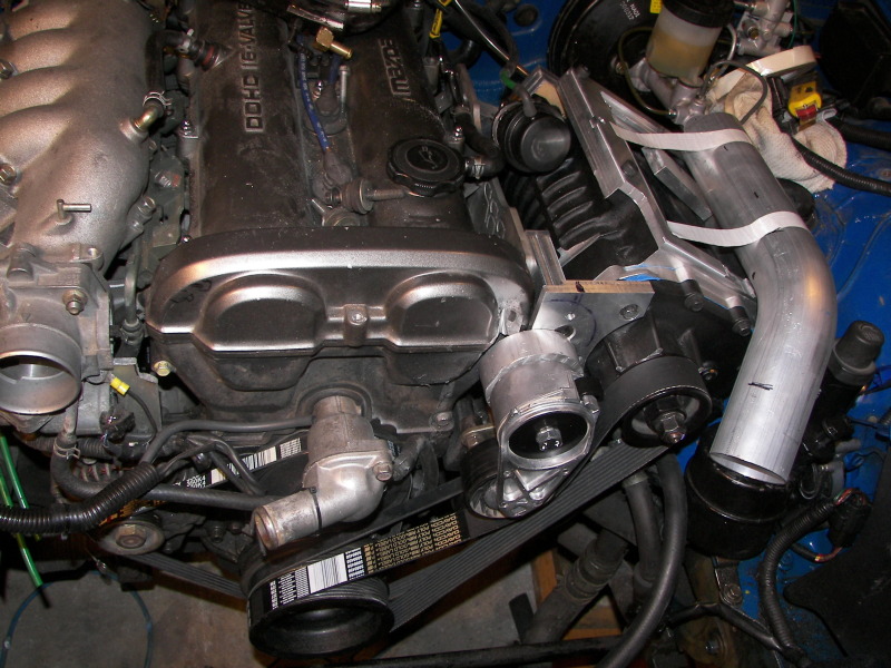
Here is how it currently looks, with these parts tacked in place. It's a bit tight, around the SC outlet. I'm probably going to be taking a hammer to the tubing....
Reply
0
0


 08-29-2011, 10:34 PM
#10
Junior Member
Thread Starter
Join Date: May 2007
Location: Toronto Area, Ontario
Posts: 327
Total Cats: 95
With my intercooler mods late last winter, I turned 252hp, and 244ftlbs on a dynojet. Prior to this, the car eaked out a 12.75 @ 109mph 1/4 mile.
Normally, as supercharger RPM's increase, the supercharger gains volumetric efficiency, generating more output flow per rev. This is why the dyno's for supercharged cars have a fairly flat torque curve. The supercharger is pumping more air per rev, as the engines internal drag increases.
This is not the case for the M90. Flow does not rise signifiantly, past about 4500 rpm and drops off quite rapidly below 2500 rpm as well. I expect the MP90 to develop more boost above and below my torque peak, resulting in more power. (I'm expecting about 50hp, but I nearly always expect more of everything, then I actually get)
Regarding the drive by wire, throttle body. It may give me 3 things.
1. As 18psi suggests, I can modify the electronic throttle opening by rpm, to produce a flatter torque curve (but at the expense of overall torque peak #'s)
2. Have a switch for the lower gears, telling the controller to reduce throttle openings, reducing torque and chance of wheelspin. (It remains to be seen, how much consistancy there will be in this)
3. Make an attempt at a more linear throttle. ie push the throttle down to 75% of wot on a SC car, and you get full acceleration which falls off as the RPM's increase. It would be nice to be able to open the throttle to 75%, and get 75% torque over the entire RPM band. (This would only work at higher throttle settings, otherwise the boost at the intercooler would spike too high, and it remains to be seen, how well this would work)
Also, I could also have a switch, that would limit boost to 5psi, or something, should I ever decide to let my wife drive it.
what benefit do you expect with the new blower?
This is not the case for the M90. Flow does not rise signifiantly, past about 4500 rpm and drops off quite rapidly below 2500 rpm as well. I expect the MP90 to develop more boost above and below my torque peak, resulting in more power. (I'm expecting about 50hp, but I nearly always expect more of everything, then I actually get)
Regarding the drive by wire, throttle body. It may give me 3 things.
1. As 18psi suggests, I can modify the electronic throttle opening by rpm, to produce a flatter torque curve (but at the expense of overall torque peak #'s)
2. Have a switch for the lower gears, telling the controller to reduce throttle openings, reducing torque and chance of wheelspin. (It remains to be seen, how much consistancy there will be in this)
3. Make an attempt at a more linear throttle. ie push the throttle down to 75% of wot on a SC car, and you get full acceleration which falls off as the RPM's increase. It would be nice to be able to open the throttle to 75%, and get 75% torque over the entire RPM band. (This would only work at higher throttle settings, otherwise the boost at the intercooler would spike too high, and it remains to be seen, how well this would work)
Also, I could also have a switch, that would limit boost to 5psi, or something, should I ever decide to let my wife drive it.
Reply
0
0
08-31-2011, 10:42 PM
#12
Junior Member
Thread Starter
Join Date: May 2007
Location: Toronto Area, Ontario
Posts: 327
Total Cats: 95
hmm, forgot to list the main reason why I'm using a DBW throttle body.
I have dual throttle bodies, one being in the standard position, and one at the inlet of the supercharger. Adding the throttle body in the standard position, is normally done to improve idle and part throttle drivability on superchargered cars with large intercoolers.
When you add a second throttle body, you need to syncronize them at WOT and at idle. After doing this, I found that there was a huge imbalance in boost, at part throttle between the intake manifold, and the output of the supercharger. I could be running 70map in the intake, and have 150map in the intercooler. This caused drivability and fuel economy issues.
anyway, here are the details on the throttle controller.
Essentially, it uses a standard Megasquirt 1 cpu (programmed with MSextrahires), which has the MAP input, attached to the TPS of the primary throttle body. This way, the main VE table, will be based on RPM and Throttle position. The injector output, is fed into a TINY45 cpu, which has code which measures the pulsewidth and then feeds this to a DAC. So the TINY45 cpu, and DAC convert the injector pulswidth to a voltage. This DC voltage is fed into a Pololu JRK 21v3 brushed motor controler. The JRK21v3 is a $50 module, which has several methods of control and feedback (I am using 0-5v for both). It has a USB input, which allows you to run a setup program which makes it easy to fine tune the PID settings for your particular system, as well as a host of other parameters.
This gives me pretty good control the Ford throttle body, allowing me to set any throttle position, based on the primary throttles position and engine RPM.
The MS1, supports nitrous oxide, by monitoring an input pin, and switching to a different VE table when that pin is tied low. In normal situations, you would use this table to add additional fuel. (increasing the injector pulse width) In this case, I would use lower numbers in this table, which would reduce the injector pulse width(less throttle) I am selecting this table, when I am in first and second gear. This will allow me to reduce the maximum boost while in these gears. I can connect an additional switch, on 1st gear, which would connect another resistor, for the IAT, telling the megasquirt, that the air temp is high, reducing the pulse width further.(this could be an adjustable resistor that could be tuned). This would also set the pulsewidth shorter, closing the throttle further. This would give me a further reduction of maximum throttle (boost) when in first gear. How well this would work, remains to be seen, however, I have to try it. I am not sure how much, different intake air temperatures will affect the settings....
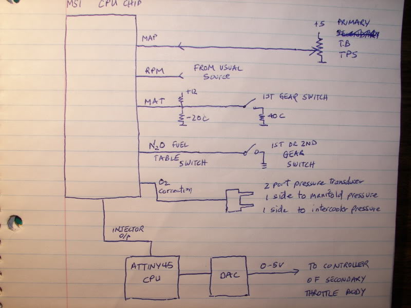
In addition, I have a 2 port pressure transducer, tied into the o2 correction input on the Megasquirt. If I set the O2 switch voltage, to the same voltage which is normally output from the 2 port pressure transducer at lets say 1psi difference, then the megasquirt will vary the throttle position (injector pulsewidth) until it gets this 1psi difference. This will allow me to easily tune the different points in the VE map, and allow the unit to correct while at part throttle, even if the targets are way off.
This is what the final product looks like
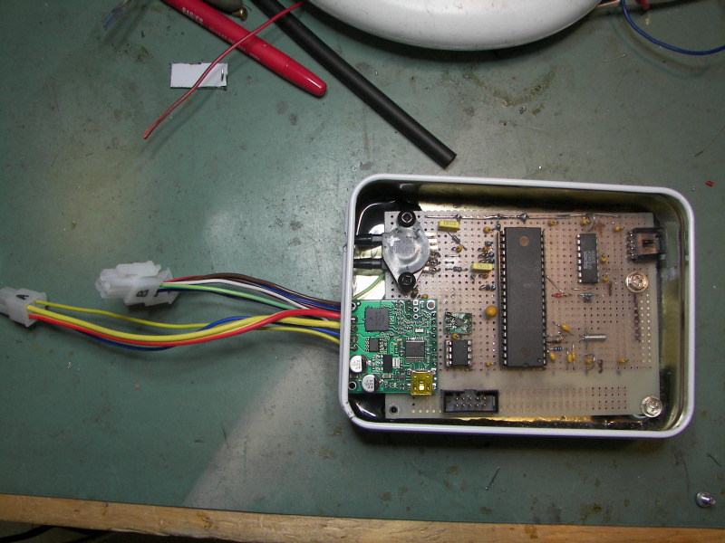
I've got this working pretty well on the bench, including the O2 correction. One issue, is that at low rpm, if you move the primary throttle quickly, the DBW throttle moves in steps, since there are not many injector pulse signals per second. Once you get up in rpm, things smooth out. It will be interesting to see how it works in the car...
I have dual throttle bodies, one being in the standard position, and one at the inlet of the supercharger. Adding the throttle body in the standard position, is normally done to improve idle and part throttle drivability on superchargered cars with large intercoolers.
When you add a second throttle body, you need to syncronize them at WOT and at idle. After doing this, I found that there was a huge imbalance in boost, at part throttle between the intake manifold, and the output of the supercharger. I could be running 70map in the intake, and have 150map in the intercooler. This caused drivability and fuel economy issues.
anyway, here are the details on the throttle controller.
Essentially, it uses a standard Megasquirt 1 cpu (programmed with MSextrahires), which has the MAP input, attached to the TPS of the primary throttle body. This way, the main VE table, will be based on RPM and Throttle position. The injector output, is fed into a TINY45 cpu, which has code which measures the pulsewidth and then feeds this to a DAC. So the TINY45 cpu, and DAC convert the injector pulswidth to a voltage. This DC voltage is fed into a Pololu JRK 21v3 brushed motor controler. The JRK21v3 is a $50 module, which has several methods of control and feedback (I am using 0-5v for both). It has a USB input, which allows you to run a setup program which makes it easy to fine tune the PID settings for your particular system, as well as a host of other parameters.
This gives me pretty good control the Ford throttle body, allowing me to set any throttle position, based on the primary throttles position and engine RPM.
The MS1, supports nitrous oxide, by monitoring an input pin, and switching to a different VE table when that pin is tied low. In normal situations, you would use this table to add additional fuel. (increasing the injector pulse width) In this case, I would use lower numbers in this table, which would reduce the injector pulse width(less throttle) I am selecting this table, when I am in first and second gear. This will allow me to reduce the maximum boost while in these gears. I can connect an additional switch, on 1st gear, which would connect another resistor, for the IAT, telling the megasquirt, that the air temp is high, reducing the pulse width further.(this could be an adjustable resistor that could be tuned). This would also set the pulsewidth shorter, closing the throttle further. This would give me a further reduction of maximum throttle (boost) when in first gear. How well this would work, remains to be seen, however, I have to try it. I am not sure how much, different intake air temperatures will affect the settings....
In addition, I have a 2 port pressure transducer, tied into the o2 correction input on the Megasquirt. If I set the O2 switch voltage, to the same voltage which is normally output from the 2 port pressure transducer at lets say 1psi difference, then the megasquirt will vary the throttle position (injector pulsewidth) until it gets this 1psi difference. This will allow me to easily tune the different points in the VE map, and allow the unit to correct while at part throttle, even if the targets are way off.
This is what the final product looks like
I've got this working pretty well on the bench, including the O2 correction. One issue, is that at low rpm, if you move the primary throttle quickly, the DBW throttle moves in steps, since there are not many injector pulse signals per second. Once you get up in rpm, things smooth out. It will be interesting to see how it works in the car...
Reply
0
0
 Q: So you're custom coupler for the dual TB is only some fiberglass mesh and blue RTV?
09-01-2011, 09:59 PM
Q: So you're custom coupler for the dual TB is only some fiberglass mesh and blue RTV?
09-01-2011, 09:59 PM
#14
Junior Member
Thread Starter
Join Date: May 2007
Location: Toronto Area, Ontario
Posts: 327
Total Cats: 95
Q: So you're custom coupler for the dual TB is only some fiberglass mesh and blue RTV?
wait. sorry, that's not right. -I'm using condoms, held with piano wire...
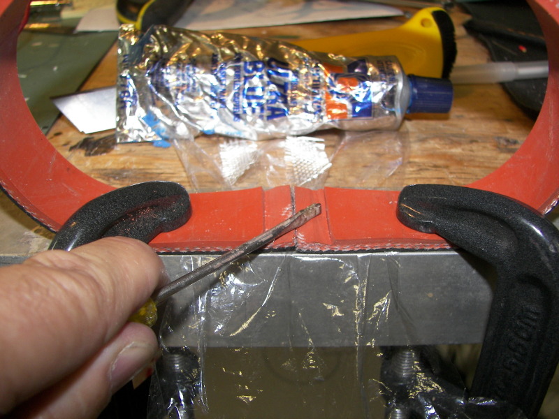
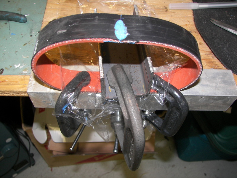
hold on. that's not right either. -I'm using fiberglass mesh and blue RTV

Actually the fiberglass mesh and blue RTV is only used to splice purchased silicone hose. I am pretty sure that the silicone hose is also reinforced with fiberglass. The resulting splice is fairly strong, and is not under much load, when attached to the throttle body...
Reply
0
0
09-06-2011, 10:42 PM
#15
Junior Member
Thread Starter
Join Date: May 2007
Location: Toronto Area, Ontario
Posts: 327
Total Cats: 95
I was busy on the weekend.
Supercharger outlet manifold nearly complete. (had to flatten it a bit, to get hood clearance)
Blow off valve, moved to be "after" the intercooler (more available space)
TB controller mostly in.
Hopefully, will get the car on the road tomorrow.
Supercharger outlet manifold nearly complete. (had to flatten it a bit, to get hood clearance)
Blow off valve, moved to be "after" the intercooler (more available space)
TB controller mostly in.
Hopefully, will get the car on the road tomorrow.
Reply
0
0

 11-06-2011, 11:27 PM
#17
Junior Member
Thread Starter
Join Date: May 2007
Location: Toronto Area, Ontario
Posts: 327
Total Cats: 95
Back from the Dead.
Well, this hasn't been a very smooth install. Maybe the nice comments from Vlad jinxed things. Ok, actually, I made a couple errors in judgement.
First off, I have had good results, using glue to hold things together. (I work for a speaker manufacturer, and speakers are held together with just glue, so am exposed to this thinking regularly). So anyway, I decided to push the envelope a bit further and decided to hold the SC outlet manifold together with glue. Oh, I used fasteners as well, but obviously not enough. Shortly after getting the car on the road, I ended up with this.
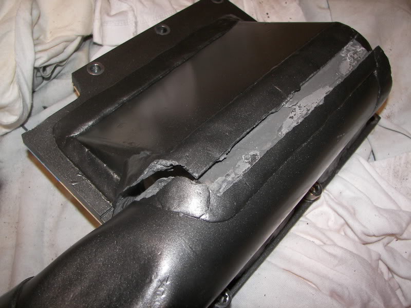
So I had it welded, put it back on the car, and then found that I was getting less boost, than my M90!!! The MP90 worked better above 5000rpm, but below that, I was down on boost by a couple of psi. Since the MP90 has much tighter clearances than the M90, and I didn't have any boost leaks, I figured that the inlet manifold was somehow hurting things. It was much larger that the M90 setup, so I reasoned that maybe I needed something that would give higher flow speeds. I made what should have been a better inlet manifold with this in mind, but unfortunately it didn't change anything.

I am going to try one further experiment later this week, using two small diameter pipes (1-1/4"), one at each side of the SC, angled so that the flow goes right where I think it needs to.
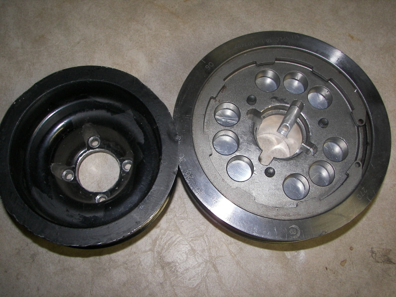
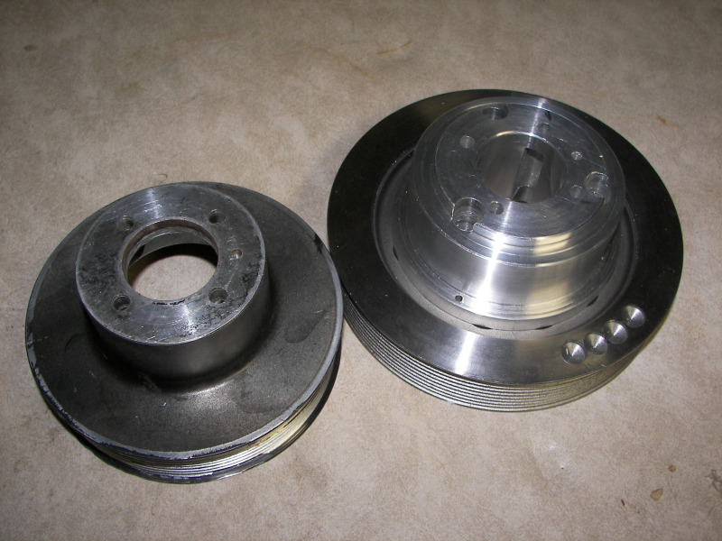
If I can't get the inlet to flow better at low rpm, then there is one other option. About a year ago, I picked up a Mustang pulley off ebay. I made a hub for it a few weeks ago. It's not nearly as elegant as my other pulley, and will be a bitch to put on, but should give me back the psi I lost at low rpm, plus make me a tiny bit more top end power. The small pulley measures 5.25", while the large measures 6.5"
I decided to make a run up to Toronto Motorsports Club, to see what the car would run in the quarter mile. Total Fail! During the first 2 runs, I had a hose pop off. Next run was ok, but the car didn't seem to rev properly after I got back to the pits. Opening the hood revealed that my 8 rib belt had transformed itself into a 4 rib belt. Not sure what happened to the other half of the belt.

Of course, I didn't have a spare, so home I went.
It turns out that while my belt alignment was good in the fore/aft position, it was not good in the other 2 axis. I knew things weren't perfect, since I had to put a .020 feeler guage at one end of the tensioner, in order to get the belt to track properly. I should not have ignored this as it was off far more than I would have guessed. Fixing this didn't change the boost situation unfortunately.
I recently removed some material from the upper vics intake manifold. Boost was going a tad over 20psi, and from what others have reported, this would make the manifold flow a little better.
Having the intake manifold throttle plates open, results in a boost reduction of 2psi at 7100rpm. It also results in a slight boost increase at low rpm, so I will have to have the MS open these plates, only when the engine is over 4000rpm. A boost drop at any rpm is good for a positive displacement supercharger, since the SC will not have to work as hard pumping, and the VE of the sc will be slightly improved as well.
On the positive side, the throttle controller works well. I have not gotten around to putting different maps in it, to reduce the boost, since the boost is so low to start with. It hasn't been a priority.
Since the car is running reasonably well, I plan on going to the dyno shortly. It will be interesting to see what the comparative numbers are...
Well, this hasn't been a very smooth install. Maybe the nice comments from Vlad jinxed things.
Ok, actually, I made a couple errors in judgement.First off, I have had good results, using glue to hold things together. (I work for a speaker manufacturer, and speakers are held together with just glue, so am exposed to this thinking regularly). So anyway, I decided to push the envelope a bit further and decided to hold the SC outlet manifold together with glue. Oh, I used fasteners as well, but obviously not enough. Shortly after getting the car on the road, I ended up with this.
So I had it welded, put it back on the car, and then found that I was getting less boost, than my M90!!! The MP90 worked better above 5000rpm, but below that, I was down on boost by a couple of psi. Since the MP90 has much tighter clearances than the M90, and I didn't have any boost leaks, I figured that the inlet manifold was somehow hurting things. It was much larger that the M90 setup, so I reasoned that maybe I needed something that would give higher flow speeds. I made what should have been a better inlet manifold with this in mind, but unfortunately it didn't change anything.
I am going to try one further experiment later this week, using two small diameter pipes (1-1/4"), one at each side of the SC, angled so that the flow goes right where I think it needs to.
If I can't get the inlet to flow better at low rpm, then there is one other option. About a year ago, I picked up a Mustang pulley off ebay. I made a hub for it a few weeks ago. It's not nearly as elegant as my other pulley, and will be a bitch to put on, but should give me back the psi I lost at low rpm, plus make me a tiny bit more top end power. The small pulley measures 5.25", while the large measures 6.5"
I decided to make a run up to Toronto Motorsports Club, to see what the car would run in the quarter mile. Total Fail! During the first 2 runs, I had a hose pop off. Next run was ok, but the car didn't seem to rev properly after I got back to the pits. Opening the hood revealed that my 8 rib belt had transformed itself into a 4 rib belt. Not sure what happened to the other half of the belt.
Of course, I didn't have a spare, so home I went.
It turns out that while my belt alignment was good in the fore/aft position, it was not good in the other 2 axis. I knew things weren't perfect, since I had to put a .020 feeler guage at one end of the tensioner, in order to get the belt to track properly. I should not have ignored this as it was off far more than I would have guessed. Fixing this didn't change the boost situation unfortunately.
I recently removed some material from the upper vics intake manifold. Boost was going a tad over 20psi, and from what others have reported, this would make the manifold flow a little better.
Having the intake manifold throttle plates open, results in a boost reduction of 2psi at 7100rpm. It also results in a slight boost increase at low rpm, so I will have to have the MS open these plates, only when the engine is over 4000rpm. A boost drop at any rpm is good for a positive displacement supercharger, since the SC will not have to work as hard pumping, and the VE of the sc will be slightly improved as well.
On the positive side, the throttle controller works well. I have not gotten around to putting different maps in it, to reduce the boost, since the boost is so low to start with. It hasn't been a priority.
Since the car is running reasonably well, I plan on going to the dyno shortly. It will be interesting to see what the comparative numbers are...
Reply
0
0
 11-08-2011, 07:54 PM
#19
Junior Member
Thread Starter
Join Date: May 2007
Location: Toronto Area, Ontario
Posts: 327
Total Cats: 95
^thanks
Murphy was at work again yesterday. My wbo2 went flakey, so I wasn't able to get the afr dialed in. New sensor won't be here till tomorrow, and of course, its exected to rain...
Murphy was at work again yesterday. My wbo2 went flakey, so I wasn't able to get the afr dialed in. New sensor won't be here till tomorrow, and of course, its exected to rain...
Reply
0
0


