My next car to sale thread
 09-16-2013, 11:55 AM
#281
Boost Czar


iTrader: (62)
Join Date: May 2005
Location: Chantilly, VA
Posts: 79,493
Total Cats: 4,080
I'm guessing I was banned because of Joe's "I'm going to give away my car just kidding I'm going to create a bid war and make as much money as possible while everyone praises me for it", thread. Funny how a mod can turn this place into ebay. The IB global rules state all threads must have a price. Free unless someone offers me money isn't a price, or else you could just post "make an offer" for everything. I was referring to that when I made the $2k bid post as a joke. A ban for a few hours would have been joking too. But for a few days is annoying and pointless.
Joe has gone rogue. I didn't notice until Lars mentioned it and I reversed it.

Reply
 0
0

0
09-16-2013, 11:59 AM
#282
Elite Member
iTrader: (13)

Join Date: Dec 2006
Location: Taos, New mexico
Posts: 6,606
Total Cats: 566
Yo dude, post your build updates over here. I looked over them at CR.net and it looked like you were doing some great work. Please don't make me read over there.. Just because a rogue mt.net mod (who doesn't even have a miata right now) banned you, don't hold it against the community as a whole!
I for one would like to read your turbo 1.6 updates over here. The new harness looked great, and the intake manifold is **** that you have. Where did you get that thing? I'm guessing this was part of the built 1.6 decision and you got it for cheap?
I for one would like to read your turbo 1.6 updates over here. The new harness looked great, and the intake manifold is **** that you have. Where did you get that thing? I'm guessing this was part of the built 1.6 decision and you got it for cheap?
Reply
0
0
 09-16-2013, 12:55 PM
#284
I'm a terrible person
Thread Starter
iTrader: (19)
Join Date: Apr 2009
Location: Arizona
Posts: 7,174
Total Cats: 180
Yes I bought his engine/coils/clutch/fw/manifold/injectors/big fuel kit/3.909 torsen. Drove a truck out and picked it all up. He is a good guy and gave me a great deal and plans to do some interesting stuff with miatas in the future.
Reply
0
0
09-16-2013, 08:16 PM
#285

Yo dude, post your build updates over here. I looked over them at CR.net and it looked like you were doing some great work. Please don't make me read over there.. Just because a rogue mt.net mod (who doesn't even have a miata right now) banned you, don't hold it against the community as a whole!
I for one would like to read your turbo 1.6 updates over here. The new harness looked great, and the intake manifold is **** that you have. Where did you get that thing? I'm guessing this was part of the built 1.6 decision and you got it for cheap?
I for one would like to read your turbo 1.6 updates over here. The new harness looked great, and the intake manifold is **** that you have. Where did you get that thing? I'm guessing this was part of the built 1.6 decision and you got it for cheap?
-Zach
Reply
0
0
09-16-2013, 09:28 PM
#286
I'm a terrible person
Thread Starter
iTrader: (19)
Join Date: Apr 2009
Location: Arizona
Posts: 7,174
Total Cats: 180
I'll post them here. Just a cross-post for now since nothing new.
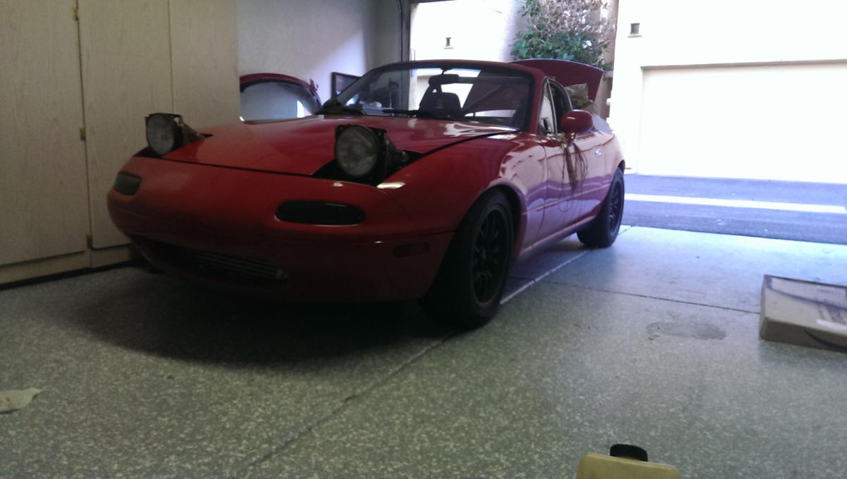
Time for an update...
I redid some of the wiring (most of it) since I wasn't 100% satisfied with it.
Here is the car as she sits now:
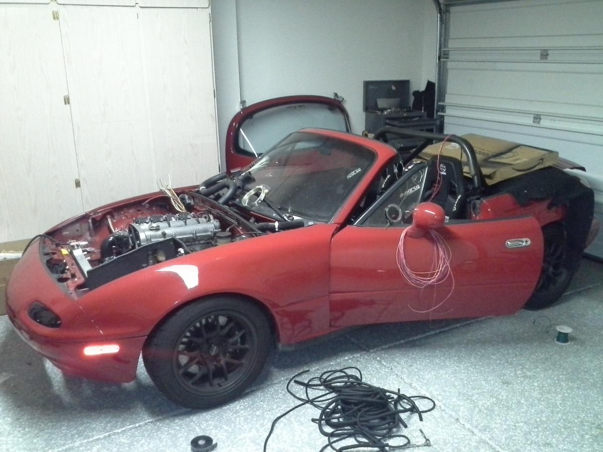
Lots of work left inside. Tomorrow I'll hopefully finish up the fuses, relays and starting/charging circuit. The dash will be going back in like I had it before.
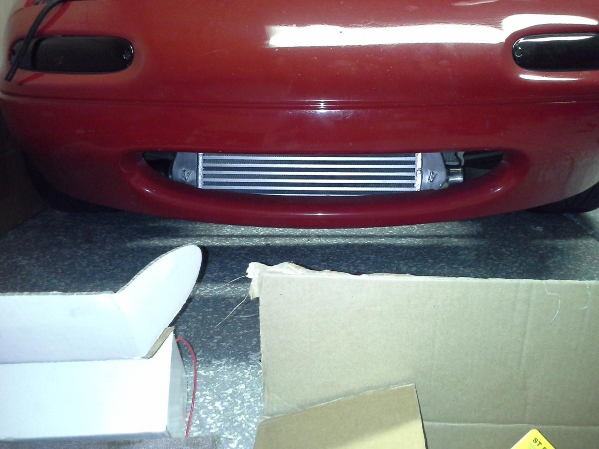
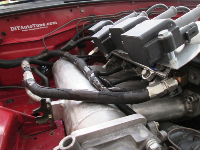
I installed an FM intercooler and piping. I love their setup, it uses very few clamps and everything fits nice. Since I will be running NA for a while this will be LOL when I have the filter in place. The new FM IC is smaller than the previous by a good bit, but this one is sized more appropriately for my power.
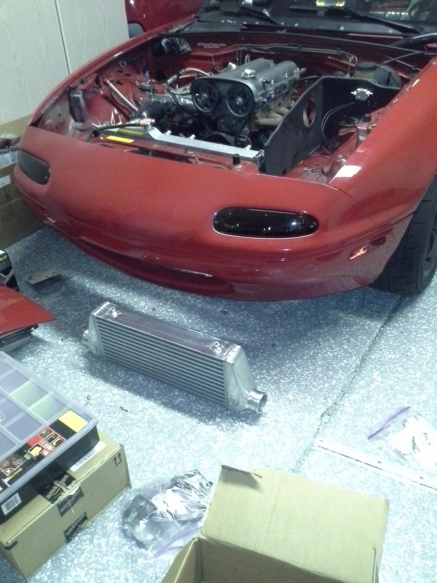
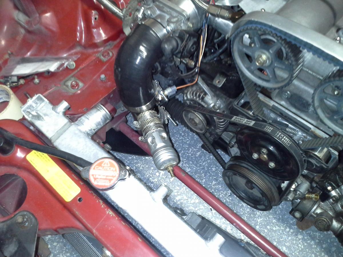
I also finished routing the coolant reroute. This fit amazingly well.
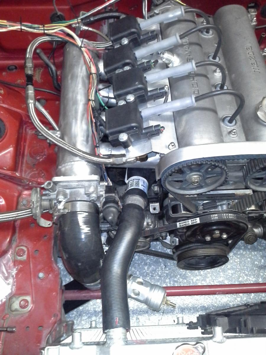
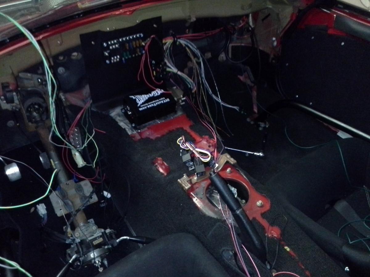
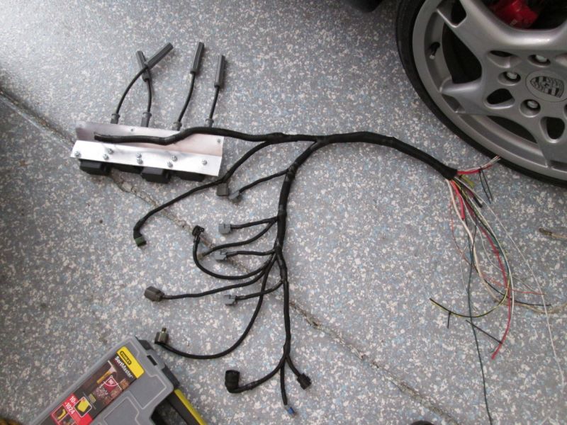
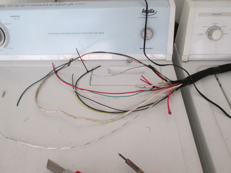
Lastly the current state of the wiring. Just about ready to wire up the big connector on the engine side. Then the MS side, and almost done!
The wires you see are:
Injectors
Coils
Knock Sensor
Coolant Temp
CAS
Air Temp
TPS
IAC
Alternator
Zip ties are to hold the wiring in place when I remove it, so that I can put on the mesh wrap correctly.
Time for an update...
I redid some of the wiring (most of it) since I wasn't 100% satisfied with it.
Here is the car as she sits now:
Lots of work left inside. Tomorrow I'll hopefully finish up the fuses, relays and starting/charging circuit. The dash will be going back in like I had it before.
I installed an FM intercooler and piping. I love their setup, it uses very few clamps and everything fits nice. Since I will be running NA for a while this will be LOL when I have the filter in place. The new FM IC is smaller than the previous by a good bit, but this one is sized more appropriately for my power.
I also finished routing the coolant reroute. This fit amazingly well.
Lastly the current state of the wiring. Just about ready to wire up the big connector on the engine side. Then the MS side, and almost done!
The wires you see are:
Injectors
Coils
Knock Sensor
Coolant Temp
CAS
Air Temp
TPS
IAC
Alternator
Zip ties are to hold the wiring in place when I remove it, so that I can put on the mesh wrap correctly.
Reply
0
0
09-16-2013, 09:28 PM
#287
I'm a terrible person
Thread Starter
iTrader: (19)
Join Date: Apr 2009
Location: Arizona
Posts: 7,174
Total Cats: 180
Glorious day of work. Stopped to go to the gym (and upload some pictures). Will do more tonight  Here are some images:
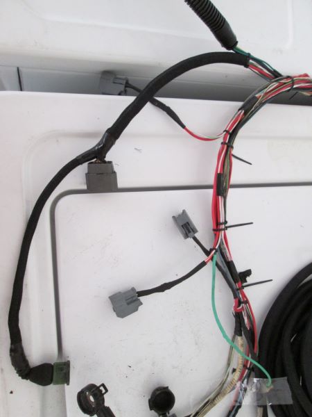
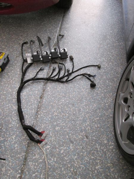
Harness off and ready to start wrapping.
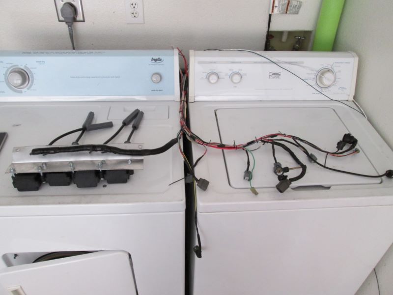
The whole harness used to be wrapped in the plastic stuff, but it wasn't very flexible, didn't look good, and wasn't durable enough. I kept it only in this one spot.
This stuff is much nicer, flexible, resists heat up to 275 degrees and is not flammable.
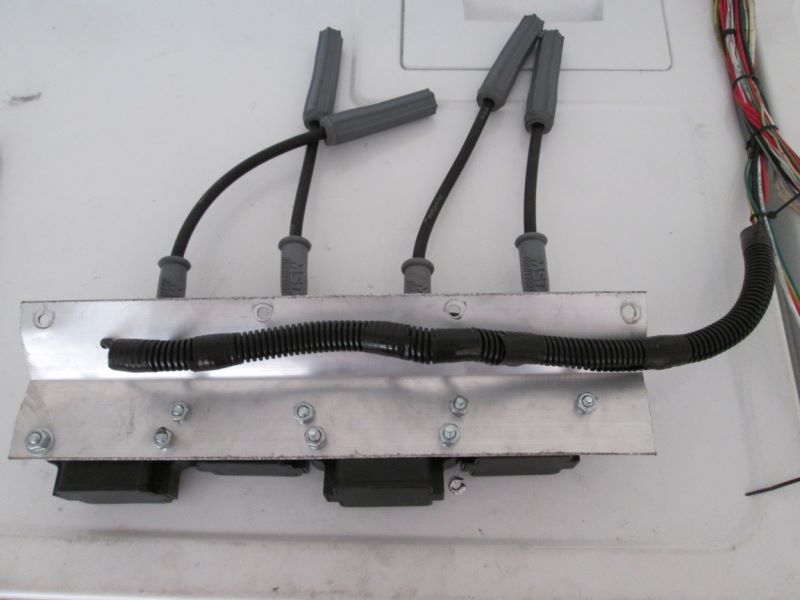
Harness is done, just needs the connector!
Here is a good look at the mesh wrap. It folds over itself so you can apply it after the wires are bundled, and it adjusts it's size so it's always a perfect fit. I held the ends together with self-vulcanizing super fire tape, which withstands direct continuous heat at up to 475 degrees.
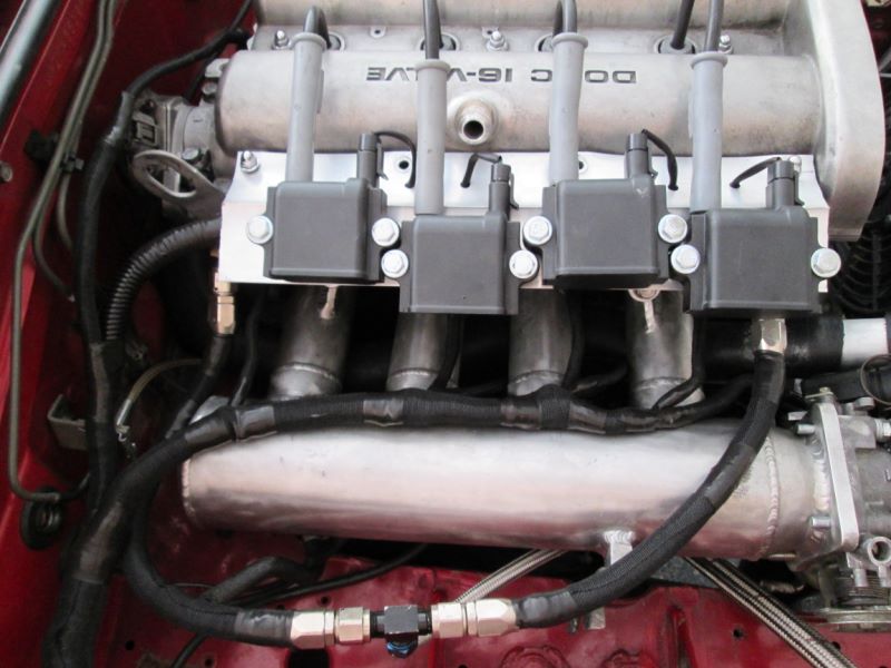
Test fitting it to the engine, all fits perfect.
nom
Time to put on the connectors. I'll be using ATX computer connectors. This is a strong connector that will hold the amperage needed and keep things clean. Two of them will be needed to keep the individual connector amp rating in check.
Here they are, clean and durable. I made a pinout diagram before assembly so I know what wires go where on the female ends. The alternator wire had to be run separate for obvious reasons (too large).
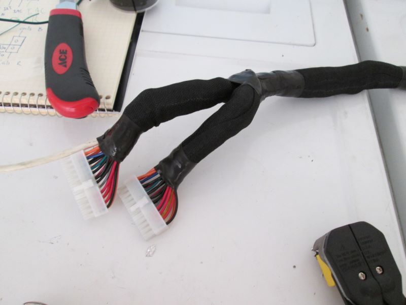
Final product ready to be installed.
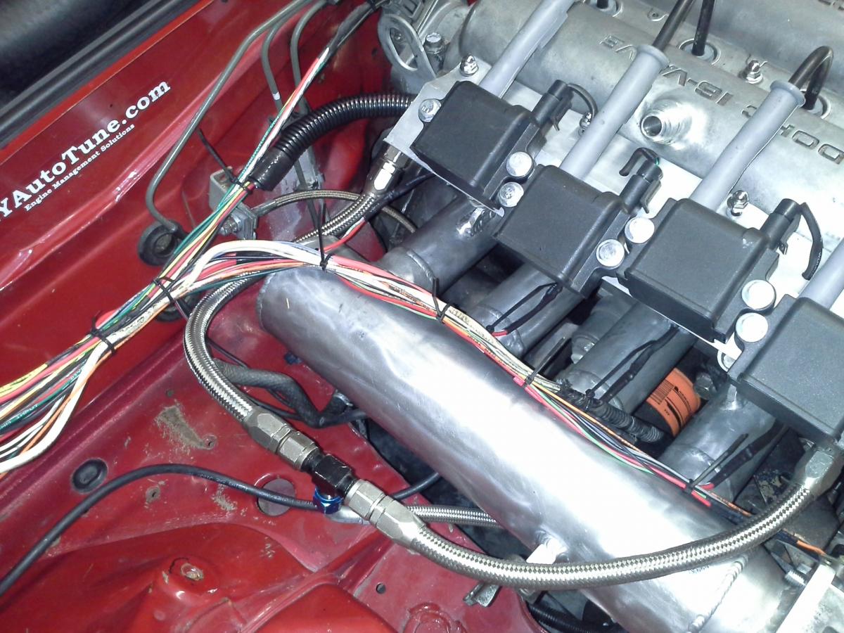
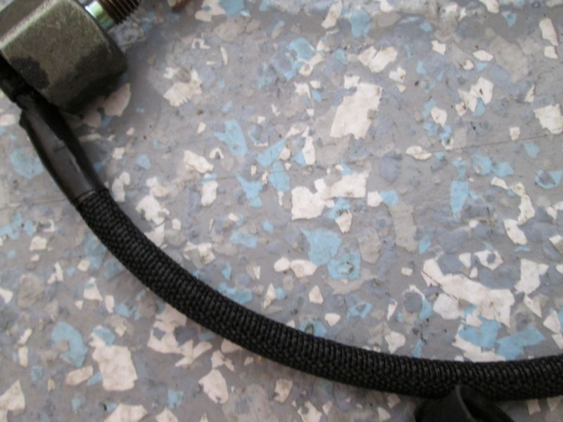
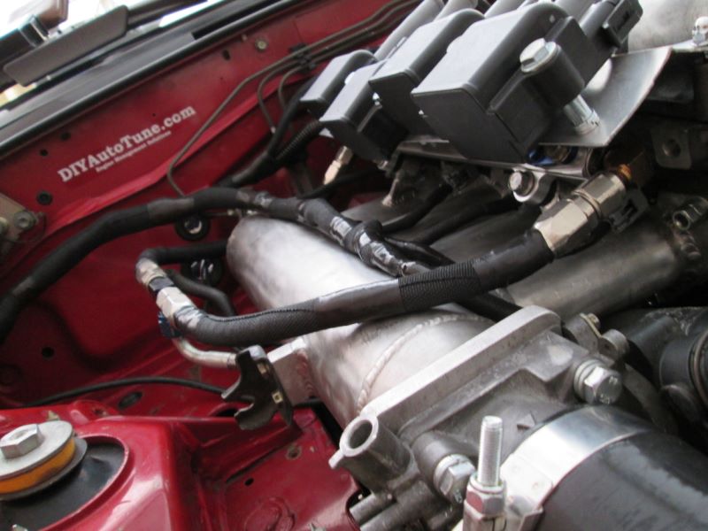
Looking good! Notice I used the same mesh wrap on the braided fuel lines. They had already started rubbing the intake manifold which is no bueno. All my braided lines will be wrapped like this. I also like black better than silver
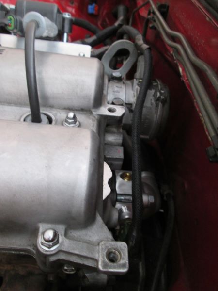
CAS and Coolant temp look a lot neater than stock!
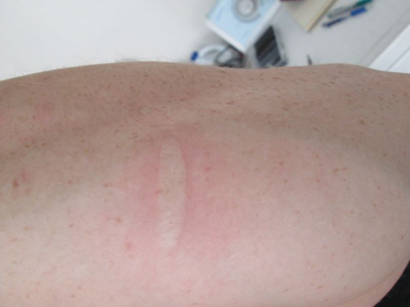
And finally this is what your arm looks like 20 seconds after resting it on a soldering iron. It is blistering now :(
Here are some images:Harness off and ready to start wrapping.
The whole harness used to be wrapped in the plastic stuff, but it wasn't very flexible, didn't look good, and wasn't durable enough. I kept it only in this one spot.
This stuff is much nicer, flexible, resists heat up to 275 degrees and is not flammable.
Harness is done, just needs the connector!
Here is a good look at the mesh wrap. It folds over itself so you can apply it after the wires are bundled, and it adjusts it's size so it's always a perfect fit. I held the ends together with self-vulcanizing super fire tape, which withstands direct continuous heat at up to 475 degrees.
Test fitting it to the engine, all fits perfect.
nom
Time to put on the connectors. I'll be using ATX computer connectors. This is a strong connector that will hold the amperage needed and keep things clean. Two of them will be needed to keep the individual connector amp rating in check.
Here they are, clean and durable. I made a pinout diagram before assembly so I know what wires go where on the female ends. The alternator wire had to be run separate for obvious reasons (too large).
Final product ready to be installed.
Looking good! Notice I used the same mesh wrap on the braided fuel lines. They had already started rubbing the intake manifold which is no bueno. All my braided lines will be wrapped like this. I also like black better than silver
CAS and Coolant temp look a lot neater than stock!
And finally this is what your arm looks like 20 seconds after resting it on a soldering iron. It is blistering now :(
Reply
0
0
09-16-2013, 09:30 PM
#288
I'm a terrible person
Thread Starter
iTrader: (19)
Join Date: Apr 2009
Location: Arizona
Posts: 7,174
Total Cats: 180
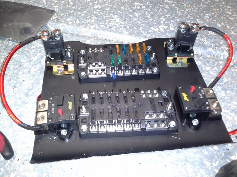
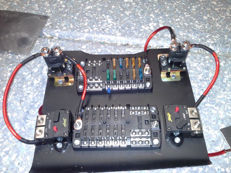
Made and test fitted all the big gauge wires for the dual 80amp breakers and 80amp relays. Battery power is supplied to the two relays from the breakers. The relays are triggered by the ignition switch. One relay is all engine stuff. The other lights, wipers, etc...
Then each relay has it's own fuse box. The fuse boxes have a positive input, which feeds all the fuses. Then there is also a negative bus on the opposite side. I'll be using one negative bus for inputs from all my sensor grounds. The other will be relay, solenoid, and various other grounds. It works out pretty well. The MS grounds (10 wires total) go to a bus that has 2 large ground straps that bolt to the engine. I also have a very very large ground strap for engine to frame grounding. I consider it an ideal setup, but I'm not an electrical engineer so who knows.
It looks a bit dirty because there is metal and stuff all over from drilling holes, and the fuse boxes are crooked. You wont see them once they are installed (against firewall behind dash). These will be a (organized) rats nest of wires once everything is connected, you won't even see the black sheet metal.
Reply
1
1
 09-16-2013, 11:30 PM
#290
Elite Member
iTrader: (13)
Join Date: Dec 2006
Location: Taos, New mexico
Posts: 6,606
Total Cats: 566
Everything is looking ****. Love the wiring, i wouldn't attempt that.
Nice IM too, what turbo are you running on this thing after all? Still greddy? If keeping the greddy look into the 19-t turbo wheel.
Nice IM too, what turbo are you running on this thing after all? Still greddy? If keeping the greddy look into the 19-t turbo wheel.
Reply
0
0
09-17-2013, 12:39 AM
#291
I'm a terrible person
Thread Starter
iTrader: (19)
Join Date: Apr 2009
Location: Arizona
Posts: 7,174
Total Cats: 180
For better or worse I'll be running a GSP 2871. I'll upgrade it when I swap in a 1.8 down the road, or when it blows up. Although I'm hoping to get a bit of life out of it.
The price of rebuilding and upgrading the greddy was too much. I have $350 into the 2871 with all adapters and oil/water feed/return. The only issue I'm having is clocking it since it uses a mount for the IWG that sits on the wrong side of the compressor and there is only one place to mount it.
The price of rebuilding and upgrading the greddy was too much. I have $350 into the 2871 with all adapters and oil/water feed/return. The only issue I'm having is clocking it since it uses a mount for the IWG that sits on the wrong side of the compressor and there is only one place to mount it.
Reply
0
0
09-21-2013, 01:43 AM
#292
I'm a terrible person
Thread Starter
iTrader: (19)
Join Date: Apr 2009
Location: Arizona
Posts: 7,174
Total Cats: 180
So just running a checklist in my head of what is ahead.
Tonight I wired up the ignition switch. I should now have power all the way up to the fuse boxes, switched on by the ignition switch. Tomorrow I may hook up the battery and check to see that it works so far.
Still need:
Flex fuel sensor connector that I have been putting off.
Wire up fuel pump + relay
Fuel level
Sensor grounds to MS
o2 Sensor
Figure out tach
power + grounds to/from fuse box
cooling fan relay/wiring
Hoping to do all of this over the weekend. Depending on time, I may try and prep the engine (fluids/etc...) and start it. Realistically this will probably happen next weekend. I have 3 tests next week so I have to reserve half my weekend for studying.
Reply
0
0
09-21-2013, 08:59 PM
#293
I'm a terrible person
Thread Starter
iTrader: (19)
Join Date: Apr 2009
Location: Arizona
Posts: 7,174
Total Cats: 180
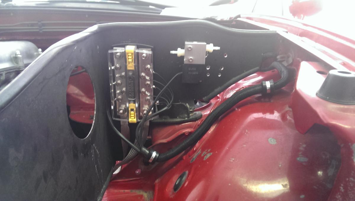
This will look 100x better once everything is connected and I go back and actually organize and the wires. Right now I'm test fitting and getting all the wires run. Once that is done I go back and verify connections with my DMM, then I add power and test voltages, then I run the car, then I secure the wires and button it up The dash will be going back in, so 99% of this won't be seen anyways.
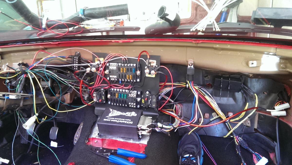
The right rear is lifted up in this photo (workin on the flex fuel sensor) so it looks a bit weird lol.
The right rear is lifted up in this photo (workin on the flex fuel sensor) so it looks a bit weird lol.
Reply
1
1
09-21-2013, 09:48 PM
#295
I'm a terrible person
Thread Starter
iTrader: (19)
Join Date: Apr 2009
Location: Arizona
Posts: 7,174
Total Cats: 180
Everything is well documented. I have pinouts for every connector, all the power/grounds that go to the fuses and negative bus, etc... I can tell you what any wire in that picture is.
It's really quite simple when you only have what you need.
I also designed the wiring diagram before I did all of this, and it worked out so I could just follow it. So I know exactly how every wire is connected, where it goes to, and what it does.
It's really quite simple when you only have what you need.
I also designed the wiring diagram before I did all of this, and it worked out so I could just follow it. So I know exactly how every wire is connected, where it goes to, and what it does.
Reply
0
0
 09-21-2013, 10:45 PM
#297
I'm a terrible person
Thread Starter
iTrader: (19)
Join Date: Apr 2009
Location: Arizona
Posts: 7,174
Total Cats: 180
Carpet isn't up currently, but already put down some coolmat type stuff on the trans tunnel and under the driver/passenger leg area. Also behind the seats/shelf area for more sound deadening than heat protection.
Reply
0
0
 09-24-2013, 08:22 PM
#300
I'm a terrible person
Thread Starter
iTrader: (19)
Join Date: Apr 2009
Location: Arizona
Posts: 7,174
Total Cats: 180
I don't remember, lol, it was like 120 degrees that day so I don't remember much besides my sweat dripping all over. I probably just added to it. My main focus was the rear deck and trunk, as that vibrates a lot. I'm going to mount a brace for the rear bumper since that seems to make the bulk of the noise back there at idle.
Tested out all the voltages and it's all good. The relays are ******* LOUD hah. They are heavy duty and should never cause issues. The breakers also also very high quality. Although I'm hoping I never have to use them.
Tested out all the voltages and it's all good. The relays are ******* LOUD hah. They are heavy duty and should never cause issues. The breakers also also very high quality. Although I'm hoping I never have to use them.
Reply
0
0


