ABSURDflow Turbo KLDE Mazda V6 Thread

 06-03-2012, 08:54 PM
#304
Elite Member

Thread Starter
iTrader: (9)
Join Date: Jun 2006
Location: Chesterfield, NJ
Posts: 6,893
Total Cats: 399
haha, yeah, budget was whatever was in 'my' bank acct after selling all of yous guys fancy hardparts for the past 4 years or so. Somewhere around $10k. The old engine and turbo stuffs may help recover some cost but I'm not pushing that sale in case something faefae happens and I have to yank this V6 ----.

Reply
 0
0

0
06-04-2012, 01:42 PM
#306
Elite Member
iTrader: (1)

Join Date: May 2009
Location: Jacksonville, FL
Posts: 5,155
Total Cats: 406
All joking aside, as I scrolled through the last page, I actually get a semi. I dont know if I have some sort of TIG welded stainless fetish or something, but its happened.
Keep up the good work Tim. You are my hero.
Keep up the good work Tim. You are my hero.
Reply
0
0
06-04-2012, 02:11 PM
#307
Elite Member
Thread Starter
iTrader: (9)
Join Date: Jun 2006
Location: Chesterfield, NJ
Posts: 6,893
Total Cats: 399

Reply
0
0
 06-04-2012, 10:08 PM
#309

Manifolds finally done after going thru 4 pairs of Vibrant vband flanges in order to find a set that are the "made in usa" ones that are designed correctly. The foreign ones (per the label) are designed to slip inside of 2" pipe, so the ID is a good .125" smaller. Dumb.
 Pisses me off.
On topic: you have so much space up front by the fans. I'm jealous you don't have to do anything special for the swaybar.
Reply
0
0
06-04-2012, 10:31 PM
#310
Elite Member
Thread Starter
iTrader: (9)
Join Date: Jun 2006
Location: Chesterfield, NJ
Posts: 6,893
Total Cats: 399
.013" wouldn't bother me, well within real world size for an exhaust flange. But 1/8" is dumb, as is the design change for the ID of the flange to be that much smaller than the pipe it mates onto. The only thing I can think is that with the flange larger than the pipe (logical old design) the clamp itself gets close to the flange and the raised weld 'coins' when you tighten it. If someone is sloppy with a MIG weld I can see the $$$ clamp hitting the bead, bending and not actually tightening the joint. With the larger sizes I have lying around this isn't an issue. Anyway, 2 messages with them with no reply. Odd, I typically have no problem with vibrant in the past, except for their stainless exhaust hangers not being stainless. If I'm bored I'll try again tomorrow, I'm not too motivated to make the call.
Mmmm, boners...
Mmmm, boners...
Reply
0
0
06-04-2012, 10:38 PM
#311
Elite Member
Thread Starter
iTrader: (9)
Join Date: Jun 2006
Location: Chesterfield, NJ
Posts: 6,893
Total Cats: 399
RE: Sway bar. That's an old Racing Beat solid bar for a 1.6. There's some grooves thru the powdercoating on the backside from it kissing the 1.8 crank pulley. I guess the 1.6 bars are more rearward than the later bars? It works for me now because my 2.5" intercooler pipe is going between the bar and the radiator fans.
Reply
0
0
06-15-2012, 10:40 PM
#313
Senior Member
iTrader: (1)

Join Date: Sep 2011
Location: Lambertville, NJ
Posts: 1,215
Total Cats: 74
JasonC suggested I use the Arduino to output variable PWM per temp sensor input signal to the BMW sourced electrical waterpump. I purchased a beginners book along with the gizmo that gives code for controlling led brightness per POT/resistance input. I just need to use a component to translate the 5v Arduino PWM output to 12vdc that the waterpump wants to see. Jason told me what to buy but it's still Greek to me. I am sure it's simple once I read thru it. I also want to build a simple lcd display so I can see what the Arduino is reading and what it supposedly is outputting. I think there are enough outputs.
Do you have any old MOSFETs from a MS build lying around that you could use for driving the pump? An OP-Amp may also be helpful...
Reply
0
0
06-17-2012, 03:52 PM
#314
Elite Member
Thread Starter
iTrader: (9)
Join Date: Jun 2006
Location: Chesterfield, NJ
Posts: 6,893
Total Cats: 399
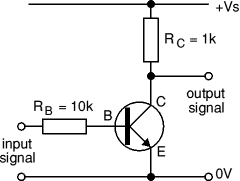
For the PWM output you just need a small MOSFET such as a 2N7000 and a 1k pullup resistor. The Arduino output is fed to the 2N7000 Gate terminal via a 10k resistor.
Or you can use a transistor such as a 2N2222, but the resistor feeding the base will be 1k.
Note that this circuit will invert the signal. E.g. 10% duty cycle turns into 90%.
Or you can use a transistor such as a 2N2222, but the resistor feeding the base will be 1k.
Note that this circuit will invert the signal. E.g. 10% duty cycle turns into 90%.
 Any recommended source for that Mosfet? I have radioshacks nearby, I also need to pick up a larger prototype breadboard and 16x2? LCD display.
Reply
0
0
06-17-2012, 08:40 PM
#315

I have the specs on the input signal from Pierburg, but basically the PWM signal to the pump needs to be close to the input voltage to the pump. Higher than the 5v the Arduino's PWM outputs produce. There is not much current at all on the PWM input, I can run little tiny signal wires to the pump. There are separate power terminals on the pump. The PWM signal 'wakes up' the pump's circuit and controls flow linearly from 15% to 100% duty. So all I really need is ~12vdc PWM signal instead of the Arduino's 5vdc. I am fairly sure I can do the temp sensor/duty cycle/LCD display code on my own, it's the 5v to 12v circuit that I am not as confident in. Maybe once remember what a Mosfet is and how the terminals get hooked up. Here's what Jason said in an email:
Mostly greek to me, no idea what a pullup resistor is, etc. But I will figure it out. Any recommended source for that Mosfet? I have radioshacks nearby, I also need to pick up a larger prototype breadboard and 16x2? LCD display.
Mostly greek to me, no idea what a pullup resistor is, etc. But I will figure it out.
Any recommended source for that Mosfet? I have radioshacks nearby, I also need to pick up a larger prototype breadboard and 16x2? LCD display.Essentially, you'll be constructing a 'low side' driver (power -> load -> FET/Transistor -> ground) , allowing the current to always flow to the input of the pump until you switch it to ground.
The other possibility would be to use a 'high-side' driver (power -> FET/Transistor -> load -> ground), which would involve using either a FET driver IC that takes a logic level input and converts it to a much higher (15-20v) output via a charge pump and an N-channel FET, or a combination P-channel FET and an NPN transistor. The second option may be easier and you could pretty much source all of the components at radio shack.
The advantage of a high-side approach is that the output duty cycle would directly correlate to the input duty cycle, but either approach will work equally well. I can provide you with circuit diagrams if you like.
Reply
0
0
06-17-2012, 10:08 PM
#316
Senior Member
iTrader: (1)
Join Date: Sep 2011
Location: Lambertville, NJ
Posts: 1,215
Total Cats: 74
^ yup.
To make it simple, you just need to build something like this circuit:
Input is a PWM output from the Arduino and output is what you think it is...
Now all that's needed is an input circuit and some code - maybe do a PID in the Arduino.
Not sure what the voltage output from the CLT sensor looks like...
Reply
0
0
06-17-2012, 11:41 PM
#317
No 'voltage output'. It's a resistive type sensor, so you'd just set the chosen ADC pin as input, and activate it's internal pullup resistor while connecting the pin to either leg of the sensor (the other side goes to ground). The sensor would act as the second resistor in a voltage divider.
Reply
0
0
06-17-2012, 11:59 PM
#318
Senior Member
iTrader: (1)
Join Date: Sep 2011
Location: Lambertville, NJ
Posts: 1,215
Total Cats: 74
No 'voltage output'. It's a resistive type sensor, so you'd just set the chosen ADC pin as input, and activate it's internal pullup resistor while connecting the pin to either leg of the sensor (the other side goes to ground). The sensor would act as the second resistor in a voltage divider.
So adding another pullup from the Arduino, you would now have two pullups in parallel, altering the effective resistance. He shouldn't mess with that.
Of course if he's using an extra coolant sensor, then he'd need the pullup.
Reply
0
0
06-18-2012, 12:21 AM
#319
Correct. However, in a normal installation there should already be a pullup in place from the ECU, effectively turning it into a voltage output.
So adding another pullup from the Arduino, you would now have two pullups in parallel, altering the effective resistance. He shouldn't mess with that.
Of course if he's using an extra coolant sensor, then he'd need the pullup.
So adding another pullup from the Arduino, you would now have two pullups in parallel, altering the effective resistance. He shouldn't mess with that.
Of course if he's using an extra coolant sensor, then he'd need the pullup.
Reply
0
0
06-18-2012, 09:31 AM
#320
Elite Member
Thread Starter
iTrader: (9)
Join Date: Jun 2006
Location: Chesterfield, NJ
Posts: 6,893
Total Cats: 399
Nah I'd use a seperate sensor just for the Arduino. The sensor that is attached to the V6's water neck looks to be the same as the OEM 1.8 miata that I will attach to the coolant pipe as well. Same connector, etc. I don't want to assume it's the same though so I will measure the resistance per temp to create my Arduino code. It will be something like, "if X ohm, output Y duty", and if the circuit flips the duty then I can have the colder resistance values output a high duty in the code. I should not need any PID for this, I will be running a thermostat.
The least amount of components the better. If I can get away with one Mosfet and some resistors that I can go pickup at radioshack at lunch, that'd be ideal.
Isn't a mosfet just a quick relay? The 5v from the Arduino goes to the gate, 12volt to the source, and the waterpump to the drain? Why can't it be that simple (i.e. why the resistors)? Again there is not a high current requirement. Are the resistors just for current limiting so the Mosfet doesn't get blown out?
Reply
0
0


