ABSURDflow Turbo KLDE Mazda V6 Thread
 02-24-2012, 09:08 PM
#221
Elite Member

Thread Starter
iTrader: (9)
Join Date: Jun 2006
Location: Chesterfield, NJ
Posts: 6,897
Total Cats: 399
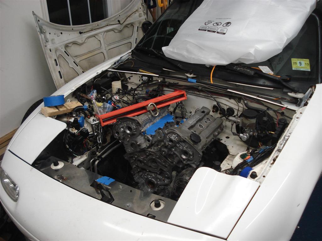
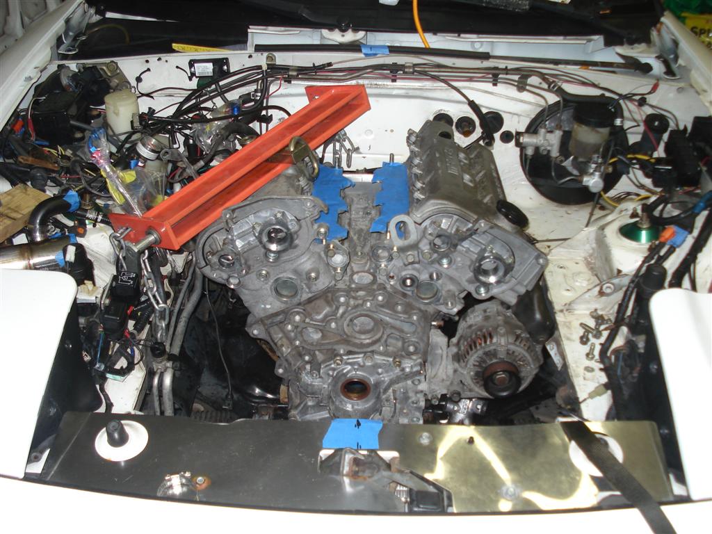
Got the V6 located where I think it should be. Driver's motor mount tacked up, passenger side has to wait until I remember to bring the starter home. Starter will crash into the subframe motormount so I'll have to make both sides of the pass. side mount.
No room for A/C, the steering shaft occupies that space. I'll have to yank out all that extra weight now. Downpipe routing is going to be interesting, it must go on the driver's side because of the starter. But on the driver's side is the alternator, oil filter boss, steering rack, clutch fork & slave, and of course the header for that bank. Fun!
I'll have to source another engine crane. The HF boom is too short even after I lengthened it.
Pics:

Reply
 0
0

0
02-25-2012, 01:17 AM
#222
Junior Member

Join Date: Aug 2008
Location: Toronto, Canada
Posts: 127
Total Cats: -1
Wow, downpipe routing sounds like it's going to be a bit tricky. Been there done that. Had to fit a 4" downpipe with fully divorced ex.wg dump tube out the engine bay with a physically larger motor too.
Reply
0
0


 02-28-2012, 03:19 PM
#224
Elite Member
Thread Starter
iTrader: (9)
Join Date: Jun 2006
Location: Chesterfield, NJ
Posts: 6,897
Total Cats: 399
Welding aluminum weakens the base material tremendously and I won't reheattreat the PPF (assuming it's heattreated at all from the factory). I will most likely keep it as originally pictured for no other reason than simplicity. I ran some quickie numbers and a good bolt will have no issue being in single shear.
Reply
0
0
02-28-2012, 10:37 PM
#225
Elite Member
iTrader: (15)

Join Date: Dec 2007
Location: San Antonio, Texas
Posts: 4,847
Total Cats: 27
Yes right on welding the aluminum. Personally I would not worry about a welded doubler plate. Maybe you could use some large washers or small plates to distribute the load a bit at the bolt hole.
I think it will be fine. The diff may be a bit noisy in the cab but again I would not worry about it. Let the awesomeness resume.
I think it will be fine. The diff may be a bit noisy in the cab but again I would not worry about it. Let the awesomeness resume.
Reply
0
0
02-29-2012, 09:50 AM
#226

If you have to make a front mount for the diff anyways why not go with an FC clutch pack diff? They hold alot better then the torsens from what i have read. I personally dont even have faith in the aluminium housing, i just broke the arm off my 1.8 open diff housing, broke 3 1.6 vlsd diffs before that, and my car is only making about 200ftlbs i assume.
Another good option would be the 8.8 just because of simplicity and aftermarket support for ratios. Get the aluminum one though or else its alot of weight. One of my close friends did an 8.8 diff swap himself with very limited fabrication skills, then had a local drive shaft shop make him some axles, all in all he spent like 450$
Another good option would be the 8.8 just because of simplicity and aftermarket support for ratios. Get the aluminum one though or else its alot of weight. One of my close friends did an 8.8 diff swap himself with very limited fabrication skills, then had a local drive shaft shop make him some axles, all in all he spent like 450$
Reply
0
0
02-29-2012, 10:14 AM
#227
Junior Member
Join Date: Aug 2008
Location: Toronto, Canada
Posts: 127
Total Cats: -1
I think the 8.8 aluminum ford diff is the way to go for sure, knowing what I know now...
When I built my setup, I wanted to keep it all mazda drivetrain, so I went with a complete driveline from an S4 FC turbo rx7 (clutch type diff vs viscous in S5)
The long nose pinion housing on the diff is kind of a pain the *** though.
FC turbo axle's have the CV boot super-close to the rear damper body though, similar to the sort of clearance issues I seen documented on m.net with other beefier diff and axel setups.
XIDA's clear fine though. Majority of the length adjustable style coilovers do not.
Reply
0
0
03-09-2012, 04:31 PM
#228
Elite Member
Thread Starter
iTrader: (9)
Join Date: Jun 2006
Location: Chesterfield, NJ
Posts: 6,897
Total Cats: 399
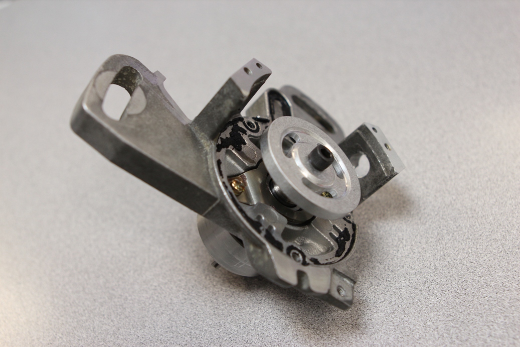
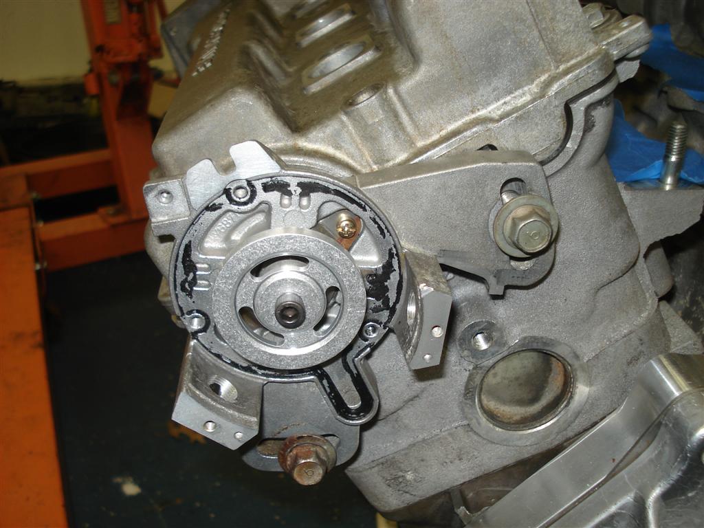
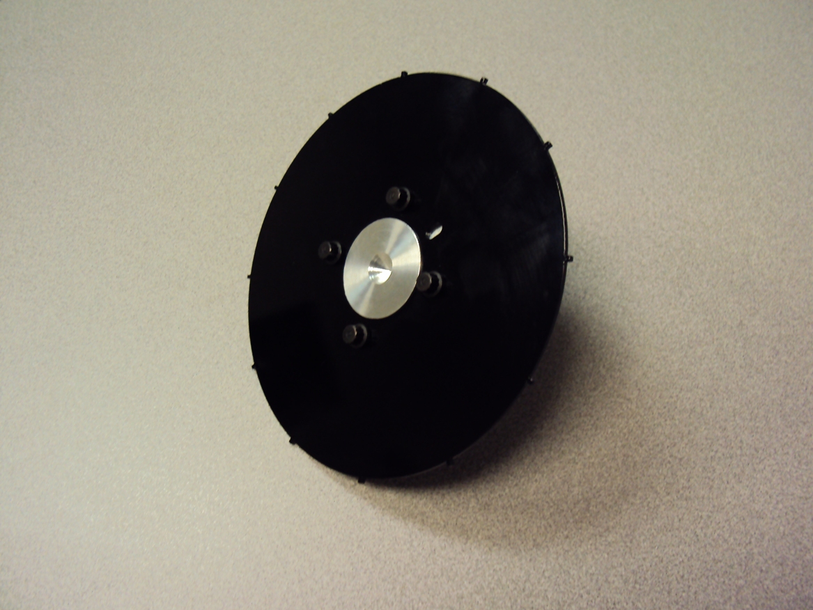
I modified the OEM distributor/cas/coilpack gizmo into a cam sensor. The back side of that aluminum wheel has a single rare earth magnet on it and I tapped the two remaining lug/standoffs in M12x1.0 for DIYautotune's hall effect sensor. I tapped both because I don't know which will give the best mounting location. I also received my 12 tooth Trackspeed crank wheel today. I have more pics, soon.
Reply
0
0
 03-11-2012, 08:52 PM
#230
Elite Member
Thread Starter
iTrader: (9)
Join Date: Jun 2006
Location: Chesterfield, NJ
Posts: 6,897
Total Cats: 399
Thanks!
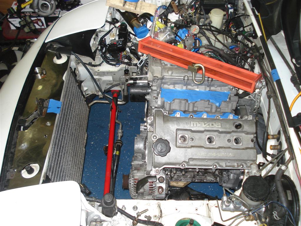
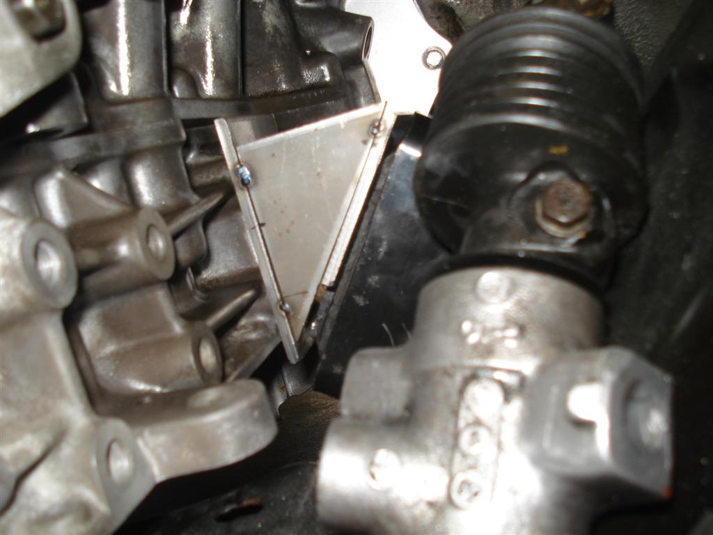
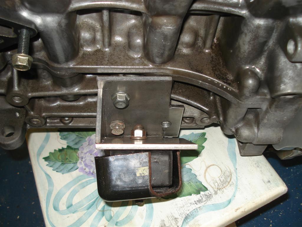
I got my motor mounts finalized today. They are just tacked together at the moment in case I had to lower the engine but they ended up fine. I have about a finger's width clearance at the oil pan rail/steering rack. I considered grinding down the steering rack and lowering the engine for additional hood/intake manifold clearance but I'd rather have the room for more oil pan capacity, for what's that's worth. Plus now I don't have to cut/retack/check.
As usual more pics here:
http://www.absurdflow.com/klde.html
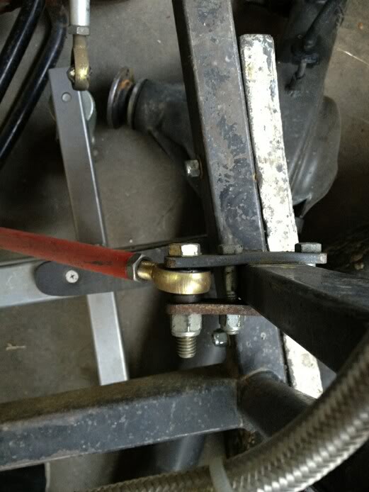
Right Mount:
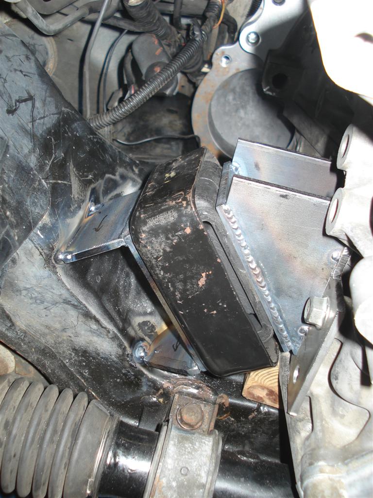
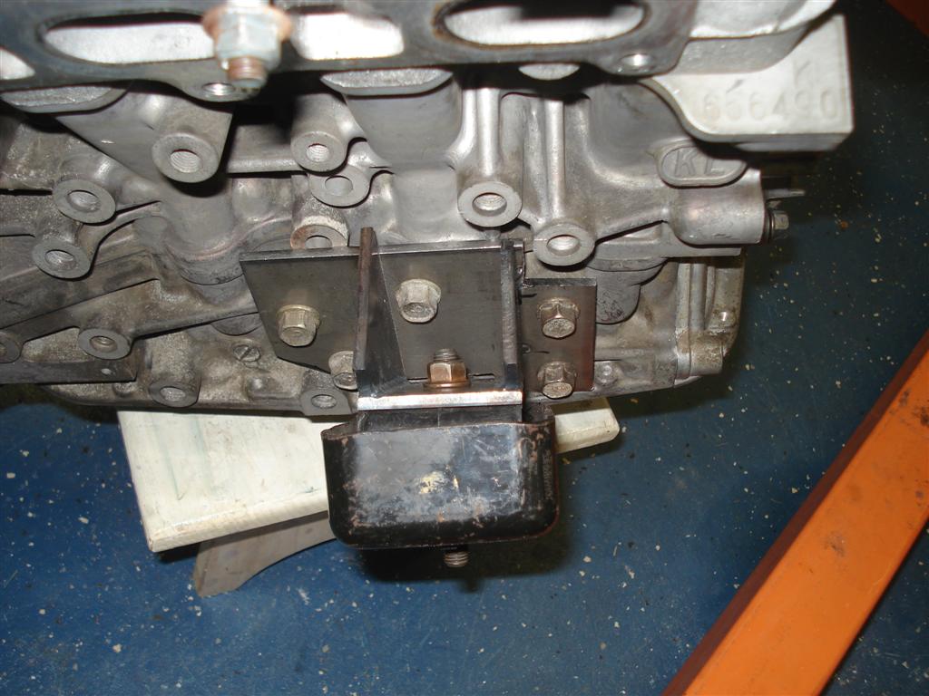
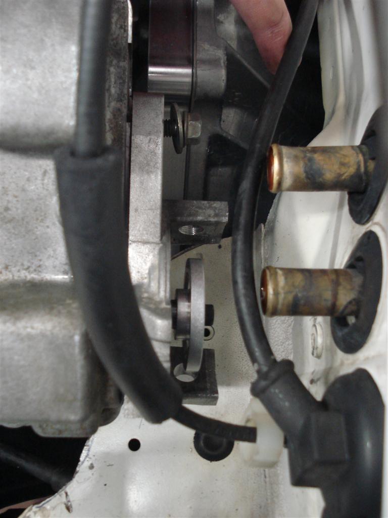
Left Mount:
My CAS gizmo on the head:
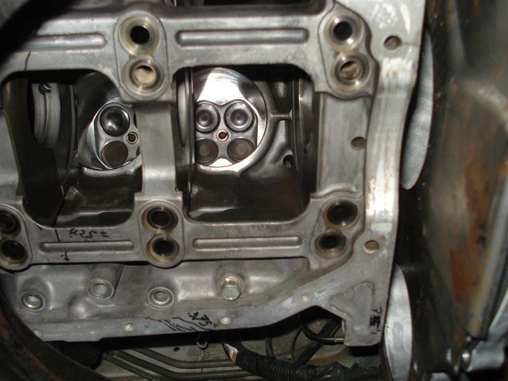
And a fun shot I thought:
I'm going to try to do the intake and exhaust flanges during lunch this week, but the next on the to-do list is the trans crossmember.
I got my motor mounts finalized today. They are just tacked together at the moment in case I had to lower the engine but they ended up fine. I have about a finger's width clearance at the oil pan rail/steering rack. I considered grinding down the steering rack and lowering the engine for additional hood/intake manifold clearance but I'd rather have the room for more oil pan capacity, for what's that's worth. Plus now I don't have to cut/retack/check.
As usual more pics here:
http://www.absurdflow.com/klde.html
Right Mount:
Left Mount:
My CAS gizmo on the head:
And a fun shot I thought:
I'm going to try to do the intake and exhaust flanges during lunch this week, but the next on the to-do list is the trans crossmember.
Reply
0
0
03-11-2012, 10:46 PM
#231
Junior Member

Join Date: Mar 2010
Location: onion city,ca
Posts: 413
Total Cats: 2
I wish u luck sir. not saying it won't work, but if you've seen what happened to me you'll understand my skepticism. i'm redoing things to return the rear subframe area back to stock.
Reply
0
0
03-12-2012, 09:08 AM
#233
Junior Member
Join Date: Aug 2008
Location: Toronto, Canada
Posts: 127
Total Cats: -1
Motor mounts look good, similar to how I built mine.
re: https://www.miataturbo.net/attachmen...ine=1331513552
Oh snap, about to mock up the stroker eh?
re: https://www.miataturbo.net/attachmen...ine=1331513552
Oh snap, about to mock up the stroker eh?
Last edited by GT42R; 03-12-2012 at 10:17 AM.
Reply
0
0
03-12-2012, 10:21 AM
#234
Elite Member
Thread Starter
iTrader: (9)
Join Date: Jun 2006
Location: Chesterfield, NJ
Posts: 6,897
Total Cats: 399
Yep, 2.5 is a stroker compared to the 1.8 I guess. Haha.
back to the diff mount....I am making my own trans cross member and I will probably modify the original PPF to mount to the cross member or something of the sorts, instead of the heim joint to the rear subframe. So the PPF will be almost as long as originally. At least that's the idea at the moment, I won't know if it'll be simple to do until after the trans crossmember is in.
back to the diff mount....I am making my own trans cross member and I will probably modify the original PPF to mount to the cross member or something of the sorts, instead of the heim joint to the rear subframe. So the PPF will be almost as long as originally. At least that's the idea at the moment, I won't know if it'll be simple to do until after the trans crossmember is in.
Reply
0
0
03-12-2012, 07:21 PM
#235
Junior Member
Join Date: Mar 2010
Location: onion city,ca
Posts: 413
Total Cats: 2
I would happily be wrong about the diff design. My setup is weaker than hingstonwm, but this is what happened at 200 wheel with medium sticky autox rubber (and lots of 1st and 2nd gear).
https://www.miataturbo.net/showpost....10&postcount=6
note: changed my mind from the time i wrote that. going back to stock design with a tranny adapter
https://www.miataturbo.net/showpost....8&postcount=25
https://www.miataturbo.net/showpost....10&postcount=6
note: changed my mind from the time i wrote that. going back to stock design with a tranny adapter
https://www.miataturbo.net/showpost....8&postcount=25
Reply
0
0
 03-14-2012, 10:51 AM
#237
Elite Member
Thread Starter
iTrader: (9)
Join Date: Jun 2006
Location: Chesterfield, NJ
Posts: 6,897
Total Cats: 399
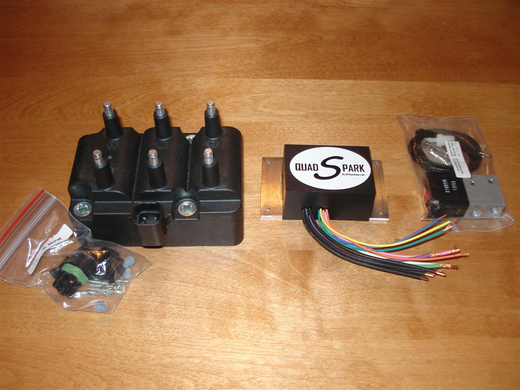
So the cam pickup would only be needed really for sequential fuel. I'm running the wasted spark cause AEM EMS only has 5 coil outputs. DIYAutotune makes this coilpack seem like it's badass
 it will be easier to get plug wires too instead of tracking down 2 more toyota COPs and modifying them to fit the V6 sparkplug hole, plus my toyota COPs don't like the cold weather.
Reply
0
0
03-14-2012, 12:31 PM
#238
Elite Member
Thread Starter
iTrader: (9)
Join Date: Jun 2006
Location: Chesterfield, NJ
Posts: 6,897
Total Cats: 399
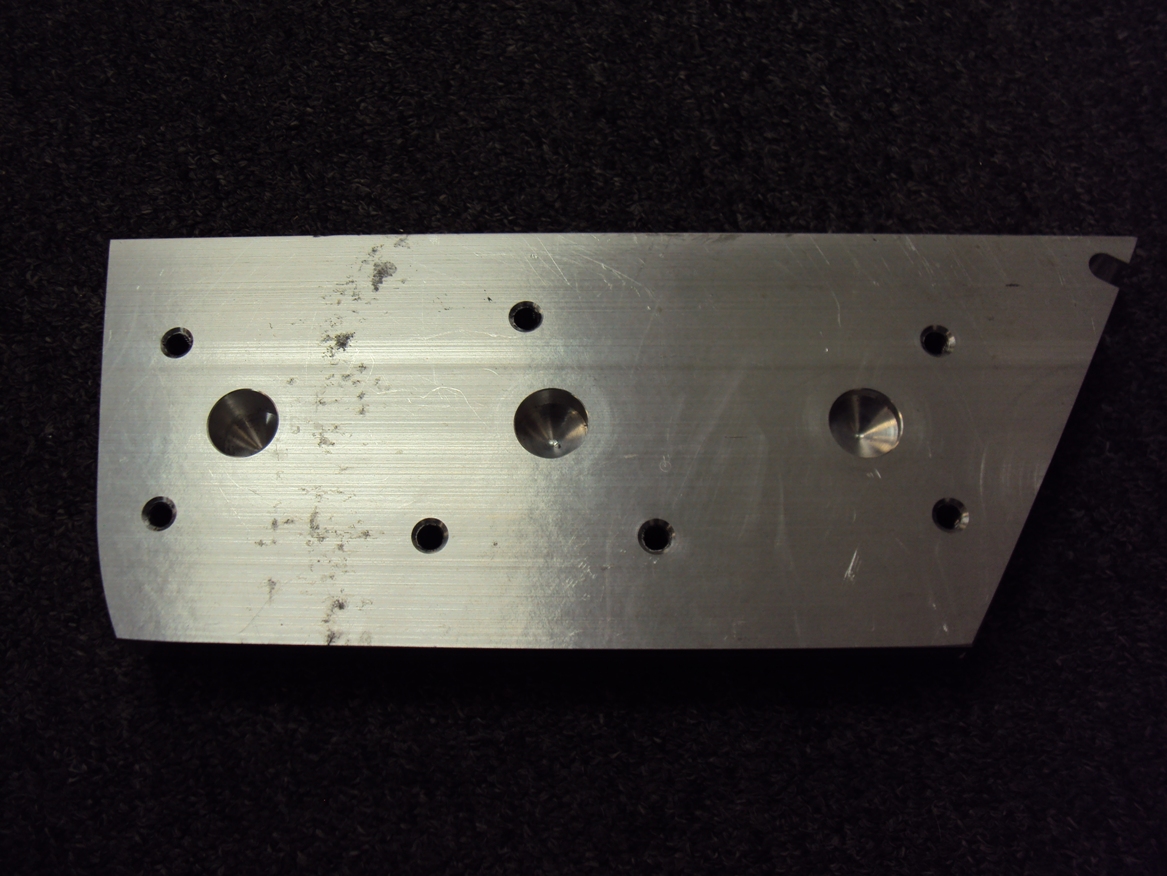
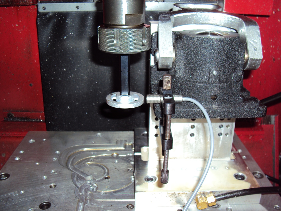
This week during lunch I made a fixture for machining the exhaust flanges and an arbor to spin my Trackspeed crank trigger wheel in a CNC here (10k rpm spindle), to see if it triggers DIYAutotune's hall effect sensor.
Reply
0
0
03-14-2012, 12:52 PM
#239
Junior Member
Join Date: Aug 2008
Location: Toronto, Canada
Posts: 127
Total Cats: -1
hmm... nice machine work!
I think you would the ideal guy to bring a fix around for the fucked-up upper spring seat situation for the XIDA clubsports w/ NB top hats.
I'm currently spinning some aluminum custom seats on the lathe, to properly adapt the 2.25" id springs to the NB top hats included with the XIDA CS.
I think there would be a bit of a market for these absurdflow could take advantage of.
Reply
0
0
03-22-2012, 11:41 AM
#240
Elite Member
Thread Starter
iTrader: (9)
Join Date: Jun 2006
Location: Chesterfield, NJ
Posts: 6,897
Total Cats: 399
Round aluminum with holes in it is simple. Perhaps once I'm done with this project. I'm not doing anything until then.
This oil pan is kicking my *** and I just started it. It can be real simple and have 3-3.5 quart capacity. Getting it to ~5 will require funky stuff making it a pain to build and a pain to install. Oh well, that tubular subframe I was considering would have come in handy now. Hopefully the pan will be done soon then the transmission cross member. I have all the raw material and trans mount here ready to go. Once that and the oil pan is done I think I can actually assemble the engine...dayum. Oh, I got the starter clearance done, just need to patch the huge hole.
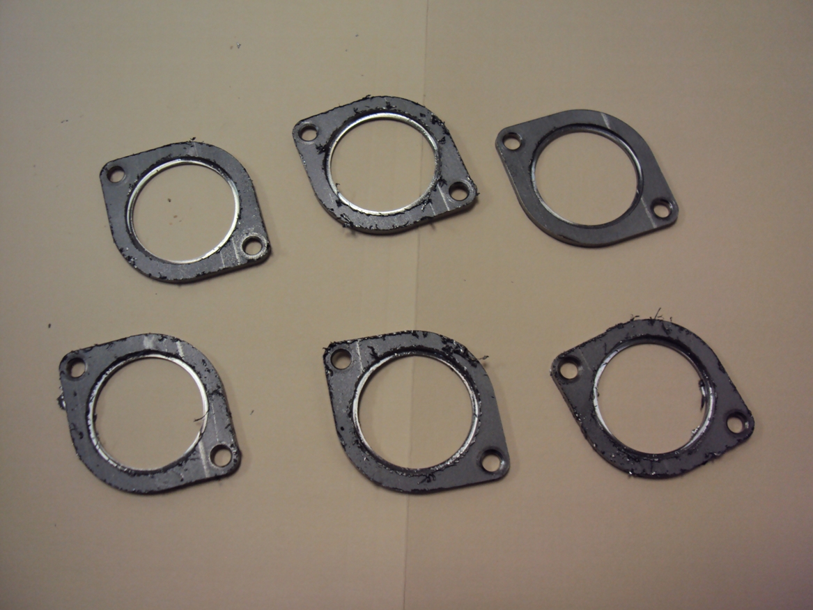
At lunch I am trying to learn me some CNC. baby steps. Here are my intake runner flanges from 1/8" 304 stainless. I went thru 3 end mills. Full-suck.
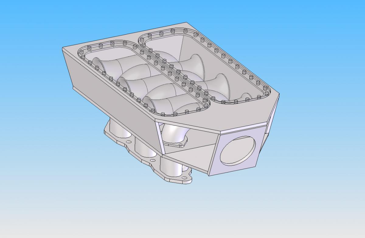
Here is the current intake mani solid model. FEA says hot polycarbonite will be fine at 25psi but I dunno. I may make the cover plates out of aluminum and keep them in the trunk in case. This is my attempt at keeping the runner length sorta kinda where it theoretically should be.
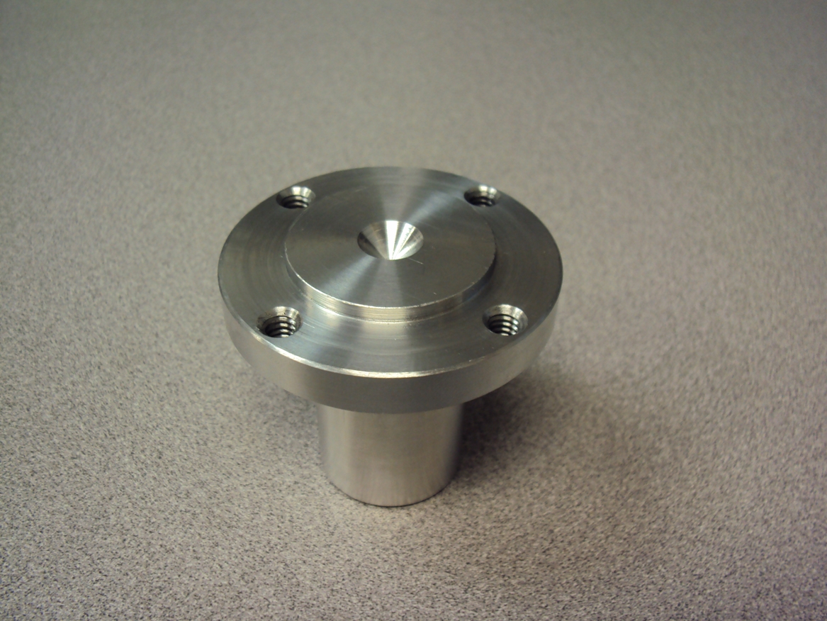
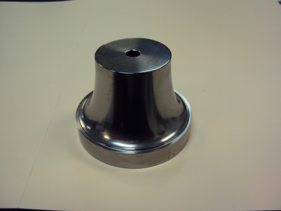
A plug that was spun off some scrap camshaft tool steel and REM finished (full REM process not done yet, it will be more polished than this pic). I will attempt to make the velocity stacks by pressing this into some soft stainless pipe. I doubt it will work, but it's thru hardened to 55Rc in case I need to grind a different shape to it.
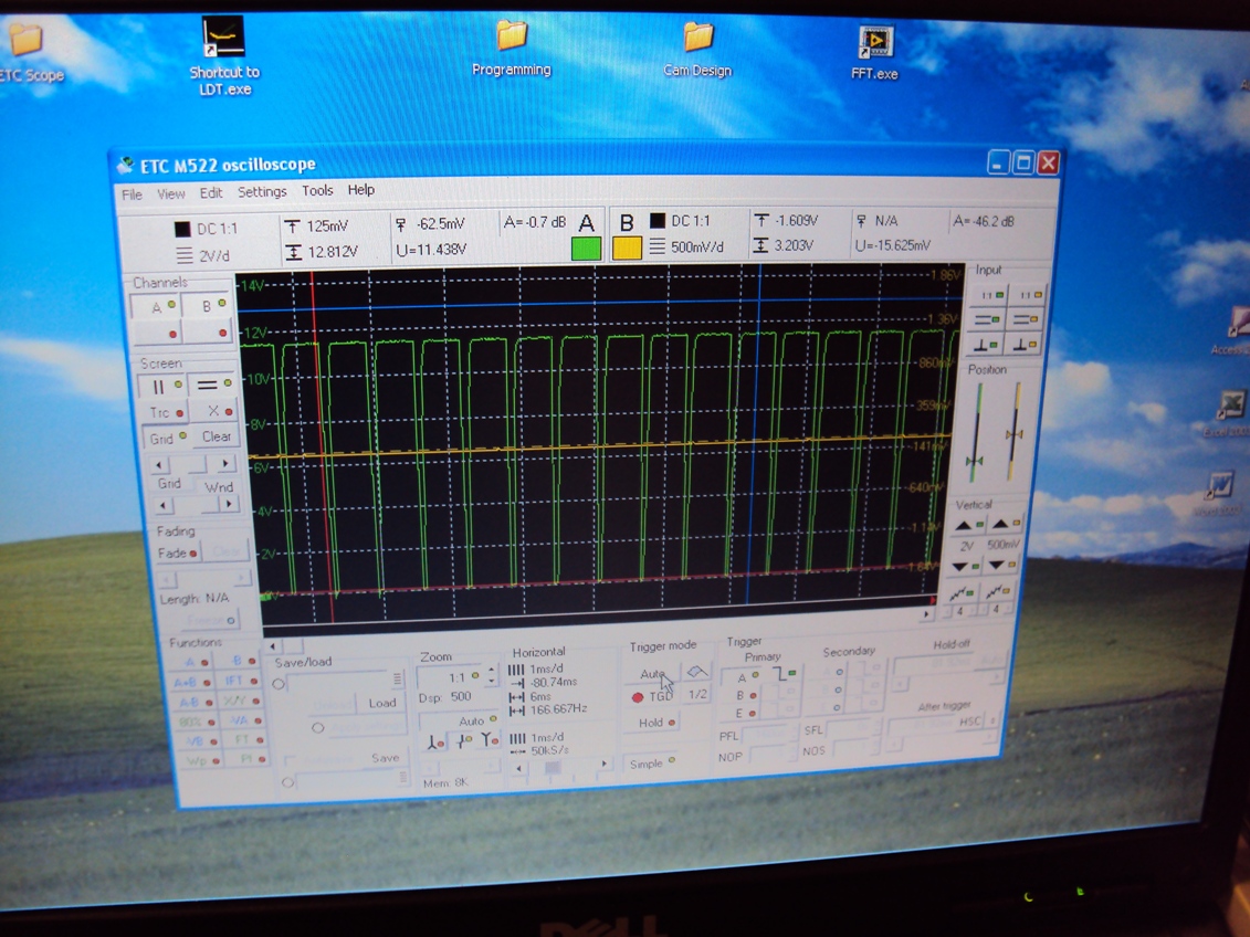
Monday I got around to spinning the trackspeed 12tooth crank wheel at 9600rpm using DIYautotune's hall effect sensor. Here's a screenshot of the scope at 9600. Max airgap I could run was .025". Looks like the trigger is on the falling edge.
I also ran Jesel's single 'tooth' magnetic wheel and the DIY sensor. This will be my cam sensor. I can run up to .275" gap with this bad boy. Apparently, depending on magnet polarity, the sensor is either a falling edge or leading edge...north pole out it produces a signal like a piece of steel would, constant voltage until the 'tooth' passes and it drops to zero. South pole out and it's constant zero voltage until the 'tooth' passes. Odd.
This oil pan is kicking my *** and I just started it. It can be real simple and have 3-3.5 quart capacity. Getting it to ~5 will require funky stuff making it a pain to build and a pain to install. Oh well, that tubular subframe I was considering would have come in handy now. Hopefully the pan will be done soon then the transmission cross member. I have all the raw material and trans mount here ready to go. Once that and the oil pan is done I think I can actually assemble the engine...dayum. Oh, I got the starter clearance done, just need to patch the huge hole.
At lunch I am trying to learn me some CNC. baby steps. Here are my intake runner flanges from 1/8" 304 stainless. I went thru 3 end mills. Full-suck.
Here is the current intake mani solid model. FEA says hot polycarbonite will be fine at 25psi but I dunno. I may make the cover plates out of aluminum and keep them in the trunk in case. This is my attempt at keeping the runner length sorta kinda where it theoretically should be.
A plug that was spun off some scrap camshaft tool steel and REM finished (full REM process not done yet, it will be more polished than this pic). I will attempt to make the velocity stacks by pressing this into some soft stainless pipe. I doubt it will work, but it's thru hardened to 55Rc in case I need to grind a different shape to it.
Monday I got around to spinning the trackspeed 12tooth crank wheel at 9600rpm using DIYautotune's hall effect sensor. Here's a screenshot of the scope at 9600. Max airgap I could run was .025". Looks like the trigger is on the falling edge.
I also ran Jesel's single 'tooth' magnetic wheel and the DIY sensor. This will be my cam sensor. I can run up to .275" gap with this bad boy. Apparently, depending on magnet polarity, the sensor is either a falling edge or leading edge...north pole out it produces a signal like a piece of steel would, constant voltage until the 'tooth' passes and it drops to zero. South pole out and it's constant zero voltage until the 'tooth' passes. Odd.
Reply
0
0


