When you click on links to various merchants on this site and make a purchase, this can result in this site earning a commission. Affiliate programs and affiliations include, but are not limited to, the eBay Partner Network.
Really, whats the size opening on the in side on those silicone intakes filters.
They have 3 different sizes on the website. The one I linked is 2.5". The filter on the inside is a cone that comes to a blunt nose, like the filter on Ford trucks. They seem decent for constructing a cold air intake. Certainly at least as good as the K&N Apollo that is many times more expensive.
Wait so the size listed is for the cold air hose? Then what size intake tubing does it fit on is the right question.
No. Size listed is for the intake tube. The open end is substantially larger. I used to have one of these and could have taken measurements, but sold it a while back.
Honestly leafy, Is this what you think will happen?
Leafy was just making a "Down Under" joke. We know that water ingestion isn't a problem for a cowl intake. Heck, some of us even do water injection on purpose.
Last edited by hornetball; 03-20-2015 at 10:01 AM.
Brain one of those inline filters with a velocity stack in the cowl could work too. If there's a space in the cowl to fit like a 7" diameter hole for the velocity stack.
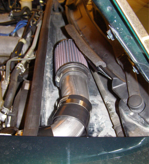
There won't be any room in my engine bay for a huge canister filter. I'll try to mount something like pictured above, or fab something up close to what hornetball made; which IMO is one of the nicest filter locations/installs I've seen.
Holiday season means that the silly season for a marketing guylike me is in full effect and I spend my time thinking of ways to improve the Miatini. I.e., reading scientific reports and studies on duct design etc.
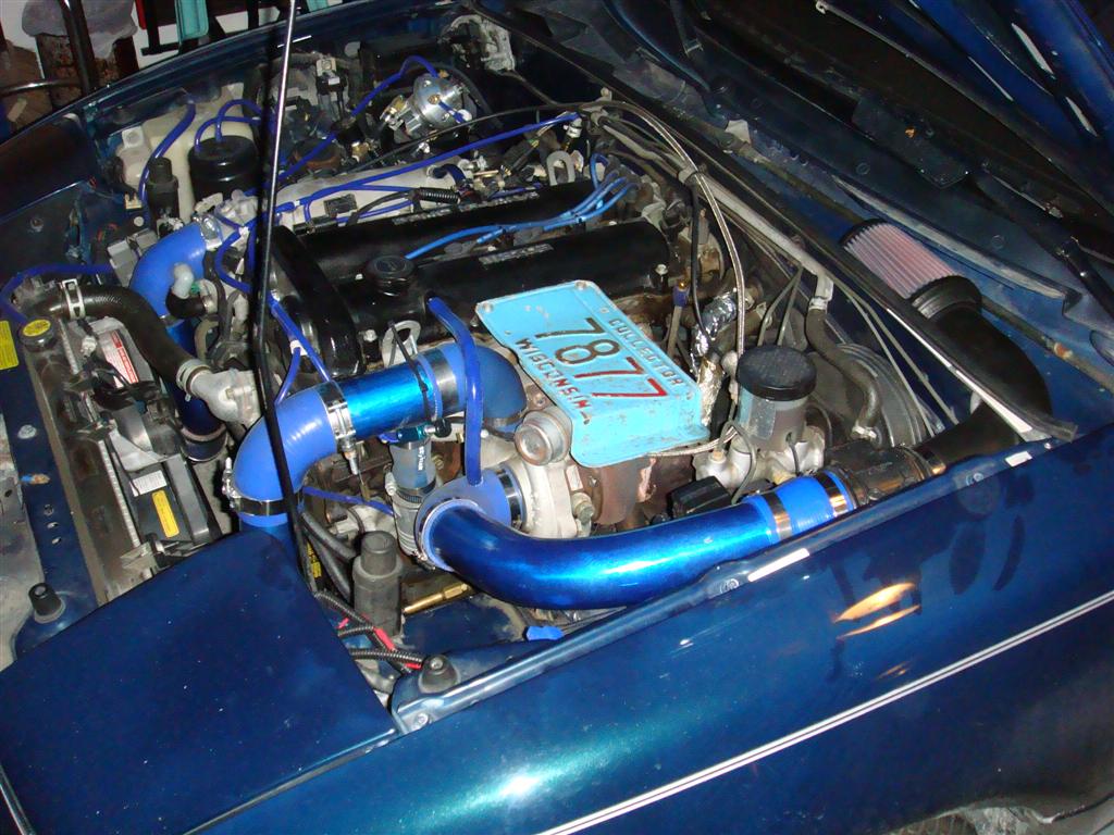
My cone filter is attached right on the compressor housing inlet (2.5") of my EFR 6758. I have been wanting to install a carbon airbox with a firewall intake as pictured above to stop drawing in hot air coming of the radiator. At the firewall I plan on installing a 2.5" bellmouth, a gentle 2.5 - 3" expanding tube attaching to the carbon airbox (3" in and out), a 3" 90� aluminium elbow with a gentle radius and to a final 90� silicone coupler that reduces the diameter from 3" back to the required 2.5" at the compressor.
Why the expanding tube?
I read an article from Willem Toet talking about expanding intake ducts to convert total positive pressure (as found near the firewall) into static pressure, of which I hope to improve intake losses between the firewall and the compressor. Also see "static regain" for that matter.
There are plenty of scientific articles out there that will explain that you need no more than 7 degrees for an expanding duct like this. Why expand? Basically because you can use the speed of the vehicle to convert that speed energy (we call it total pressure) in to static pressure (think of it as pressure that pushes on surfaces if any are there) and into air density. More density means more air (oxygen molecules in this case is the important bit) gets into the engine (and in this case it is also cooler = even more density).
Dunning Kruger confusion #1: WRC cars all have CAI, but the inlets going to the air filter box (and sometimes incorporating them) are FAR bigger than 2.5". Matter of fact only subaru seems to have employed an expanding duct (probably more due to packaging restraints).
So, while Mr. Toet went on to explain the importance of expanding ducts, none of the WRC seem to car about it and mostly rely on dynamic ram air pressure. Anybody got a clue why, or has done some testing? Clearly you try to get the least pressure drop and the least IAT increase. Would the increase in static pressure (firewall intake + expanding tube vs. pod filter behind the radiator) overcome the pressure losses caused by the longer intake?
More reading and real world testing: AutoSpeed - We Have a Record! AutoSpeed - Into the Intake - Part 1 (issues 177-180)
Possible efficiency losses due to intake elbows
According to Zhao et al. (and many other researchers, intake elbows not only pose restrictions, but also affect the efficiency of the compressor wheel itself due to non-uniformity of airflow entering the compressor, leading to later spool and worse stalling behavior:
The impact on the compressor performance is important for designing the inlet pipe of the centrifugal compressor of a vehicle turbocharger with different inlet pipes. First, an experiment was performed to determine the compressor performance from three cases: a straight inlet pipe, a long bent inlet pipe and a short bent inlet pipe. Next, dynamic sensors were installed in key positions to collect the sign of the unsteady pressure of the centrifugal compressor. Combined with the results of numerical simulations, the total pressure distortion in the pipes, the pressure distributions on the blades and the pressure variability in the diffuser are studied in detail. The results can be summarized as follows: a bent pipe results in an inlet distortion to the compressor, which leads to performance degradation, and the effect is more apparent as the mass flow rate increases. The distortion induced by the bent inlet is not only influenced by the distance between the outlet of the bent section and the leading edge of the impeller but also by the impeller rotation. The flow fields in the centrifugal impeller and the diffuser are influenced by a coupling effect produced by the upstream inlet distortion and the downstream blocking effect from the volute tongue. If the inlet geometry is changed, the distributions and the fluctuation intensities of the static pressure on the main blade surface of the centrifugal impeller and in the diffuser are changed accordingly.
Dunning Kruger confusion #2: there might be more to turbo intake design than IAT, intake pressure and pipe length. As a non-native-speaking non-engineer I#ll try to wrap my head around it and send it in the mean time.
I didn't see the point in opening a new thread if it fits the old one (unless Scott and Dann can't keep their **** together :-D )
regarding the intake diffuser: maybe I shouldn't worry so much about gaining static pressure at all. The EFR 6758 at full boost swallows some 0.2-0.25 m� of air (200-250 liters) per second (!) according to the BorgWarner Match Bot (BorgWarner MatchBot). That's a lot of air flowing through a 2.5" inlet diffuser opening. Maybe it's better to look elsewhere and build a 3D printed intake that goes across the radiator into the mouth, but is designed for turbos
Since I'm sick in bed I cannot do any pressure testing myself, so I have to rely on online calculators. Let's calculate the pressure drop of the aforementioned cowl intake with 2 x 90� bends, all 3" tubing up to the air filter box and from there to the cowl. For now let's assume both the pod filter in the carbon air box and the pod filter attached directly to the compressor housing have the same pressure drop, so we can leave those numbers aside.
Using the Pressure Drop Online-Calculator calculator, we use the following inputs: 25�, 1 bar absolute air pressure, 200 liters per second of air flow (air density 1.225 kg/m�), dynamic viscosity of 0.0185 mPa*s. The pipe roughness for rubber (silicone coupler) and aluminium are roughly (pun intended) the same @ 0.0015 mm.
90� elbow, 3" (in reality it tapers down to 2.5" to fit the compressor, but nevermind), silicone. Assumption: 150 mm radius --> pressure drop = 2.41 mbar
90� elbow, 3", aluminium pipe. 230 mm radius as given by manufacturer --> pressure drop = 2.39 mbar
90 cm of aluminium straight pipe, 3" diameter --> pressure drop = 2.33 mbar
so total pressure drop of a 3" firewall intake would amount to 7.76 mbar or 0.78 kpa (=3.13 inches of water in freedom units)
If we replaced the beginning of the 90 cm straight pipe with a diffusing inlet, starting at 2.5" and expanding to 3" at an half-angle of 10� (https://www.powersprint24.de/reduzie...-900308ps.html), we would have 34 mm of expanding tube and 866 mm of straight 3" pipe.
So the diffusing inlet actually is detrimental to performance, at least for high-flowing turbo engines or classes without a mandatory inlet restrictor. With a restrictor a diffusing trumpet might partially recover some pressure, which is probably why they are so carefully tuned.
Learning 1: make the intake pipes as large as possible. Pressure drop in a 2" / 2.5" / 3" / 4" straight pipe of 1 Meter is: 18.6 / 6.03 / 2.59 / 0.65 mbar.
Learning 2: a diffusing inlet has a negative impact at least for this application.
If I have fucked up the math or logic behind this, please feel free to correct me.
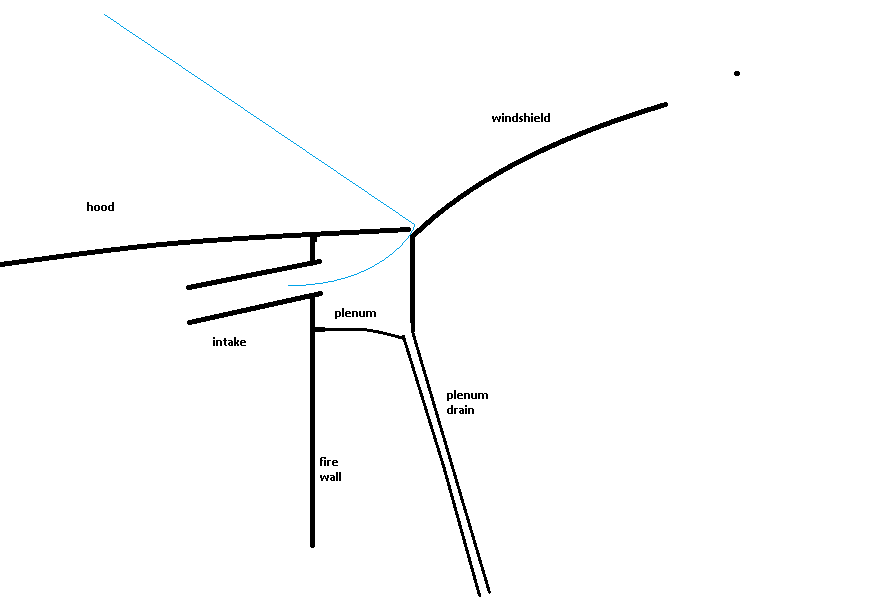
So far we haven't touched the issue of relative pressure. We all know that the cowl near the windscreen is a high pressure zone (the mouth might be even higher pressure, but that's a different matter). How high the pressure is I can only guess. A few data points:
Autospeed #1: At 70 kph (2nd gear @ 6,000 RPM) pressure drop before AFM was reduced from 25 cm/10" of water to 9 cm/3.5" when moving from a stock NA's air filter system to a cowl induction with an enclosed pod filter. Since the filter itself didn't pose much of a restriction, most gains were obtained by a) promoting better flow and b) having positive pressure enhancing the entering of air. 16 cm of water gained equals an improvement of approx. 16 kpa. How much of this we can attribute to (b) i do not know
Autospeed #2 did some pressure testing with a somewhat rounder Lexus RX300, relative to ambient (cabin) pressure at relatively low speeds (60 kph). However, I'd read the results with a grain of salt when it comes to Miata world applicability - the author recorded lower pressure in the wheel well, while Keith detected higher pressure on his miata
With 2 additional datapoints at 120 (3") and 150 kph (10" of water) one can calculate that the Lexus has approx. 1.6" water (0.4 kpa) of positive pressure at 100 kph, measured at the base of the windshield. So - as far as I understand it - that means the positive pressure cuts the intake losses in half 0.78 --> 0.38 kpa (1.5" of water) of pressure drop. And if the pressure distribution was a bit in our favor (twice the pressure, i.e. 0.2 inches at 60 kph) we might offset any losses. The lower intake temps and denser air would then be power found.
To put that into context: Autospeed's best performing intake (Prius) had a pressure drop of 4" of water (albeit including pressure drop caused by the filter)
However, with the mouth being even higher pressure we should really get going with a cobra head intake that draws air from in front of the radiator.


 03-19-2015, 06:48 PM


 0
0