LC1 Issues
 03-05-2011, 12:19 PM
#1
Junior Member
Thread Starter

Join Date: May 2010
Location: Darlington, UK
Posts: 280
Total Cats: 0
Im having a few problems setting up my LC1. I had the LC1 wired to my DIY PNP MS (Built by Brain) through the DB15 (I think its called!) port on the MS.
I had 4 wires from the MS going to it. Thye Brown wire, The Blue and White wire, And the Red Power wire. The Black wire was connected to an push button and LED but I wasnt sure it was working so I removed it to eliminate that as a possible fault.
I have never calibrated the sensor form install as Im not certain its calibrating. I have tried earthing out the wire etc but cant be sure it worked.
Im using:http://www.innovatemotorsports.com/p...s/g2_gauge.php
I think it could be an earth issue. I tried cutting the blue and white wires and earthing them direct to an earth near the stereo and the gauge needle went all the way round to the right back to the left and then back to 18 and stopped at 18. Is this correct? should the gauge do this?
How do you calibrate without the LED connected?
I have tried to power the LC1 then connect the sensor but there is no visible difference. I also connected the black wire to earth but still no difference.
However when the blue and hite ire went to the MS direct if I attached the black wire to earth the gauge did look like it was doing something. But again I was uncertaiun when it was stopped so I dont know if its worked.
I have read the LC1 handbook an still I cant be sure its correct.
Wiring summary is:
White and Blue to earth (was via the ECU)
Red to ECU (Power I assume)
Black and yellow wire taped up seperate
Brown to Ecu.

Reply
 0
0

0
03-05-2011, 12:46 PM
#2
Tour de Franzia

iTrader: (6)
Join Date: Jun 2006
Location: Republic of Dallas
Posts: 29,085
Total Cats: 375
I'd probably start by reading the directions and following them to some degree if not entirely. I'm a little confused on where you're grounding "at the MS direct". If you read the directions, you'd be more specific on where you placed the grounds.
This is all discussed, very clearly in the instructions. If you think you can ground on the body, you're beyond help.
Yes, it's normal for it to read 18:1 if you car is not running and there is no exhaust in the pipe, full lean is reasonable.
This is all discussed, very clearly in the instructions. If you think you can ground on the body, you're beyond help.
Yes, it's normal for it to read 18:1 if you car is not running and there is no exhaust in the pipe, full lean is reasonable.
Reply
0
0
03-05-2011, 01:01 PM
#3
Junior Member
Thread Starter
Join Date: May 2010
Location: Darlington, UK
Posts: 280
Total Cats: 0
The reason im not certain is I installed it following the instructions accuratly about 4 months ago. Then after I installled it I removed part of the wiring as my DIY PNP came from Brain and he wired up the plug on the MS to accept the WB sensor. So I had to remove some of the wires and then attach them to the plug which go to the MS.
Thats where the uncertanty is.
My blue and white wire went to the plug which goes to the MS. but I have chopped it today to try and see what diffence it makes by then attaching this wire to a bolt that goes through the body.
It did make a difference as when the earths goe to the connnector on the MS. The guage starts to move when you do 1 turn on the ignition nthen stops and doesnt move any further when you go to 2 clicks on the ignition.
When attached to the bolt as an earth the guage seems to opertate normal. In terms of it moves and then stops at 18 once it has do what ever it is that it does rather than stop as soon as I get to the 2nd click on the ignition.
So I guess my earth is wrong.
I think I might remove all the wires from the connector to the MS except the brown wire. Then wire them as the insructions say and see what happpens.
But please can you clarify do the blue and white wire have to be wired to the ECU earth which is in the engine bay near the inlet manifold?
Reply
0
0
03-05-2011, 01:15 PM
#4
Tour de Franzia
iTrader: (6)
Join Date: Jun 2006
Location: Republic of Dallas
Posts: 29,085
Total Cats: 375
Are you attaching the LC1 grounds to the engine or not?
What factors on your car made you consider that you should not follow the directions?
You need to read the directions and solder to a ring connector on separate lugs to the same piece of metal.
You need to read the directions and solder to a ring connector on separate lugs to the same piece of metal.
Reply
0
0
03-05-2011, 01:21 PM
#5
Slowest Progress Ever
iTrader: (26)
Join Date: Oct 2007
Location: The coal ridden hills of Pennsylvania
Posts: 6,022
Total Cats: 304
Of course I'm at the bar right now, cause it's Saturday and I'm celebrating cause I just bought 35x12.5 R17 Goodyear wrangler mtr's for my truck. What does that have to with your post? Nothing.
This does though...
When I get home which should be within the next hour, I will post a diagram of exactly what you need to do.
You're welcome.
This does though...
When I get home which should be within the next hour, I will post a diagram of exactly what you need to do.
You're welcome.
Reply
0
0
03-05-2011, 01:42 PM
#6
Junior Member
Thread Starter
Join Date: May 2010
Location: Darlington, UK
Posts: 280
Total Cats: 0
Of course I'm at the bar right now, cause it's Saturday and I'm celebrating cause I just bought 35x12.5 R17 Goodyear wrangler mtr's for my truck. What does that have to with your post? Nothing.
This does though...
When I get home which should be within the next hour, I will post a diagram of exactly what you need to do.
You're welcome.
This does though...
When I get home which should be within the next hour, I will post a diagram of exactly what you need to do.
You're welcome.
Hustler. No im not fixing the earths to the engine at present. I followed the directions. "What made you not follow the directions" I had the plug for the ECu wired for the LC1 so I could remove it easily if I wanted to.
I havent soldered the blue and white earths to a lug. I soldered them together and them had that soldered to a pin on the connector which then went to the ECU.
Reading the instructions says to join all the wires eg the blue and white and preferably solder them together and then attach them to the same lug. By lug I assume it means an earth mounting point on the car. Which 1 is my question. Again following the instructions it recommend the point at which the ECU is earthed. I think this is a bolt on the engine at the back on the ide of the inlet manifold.
I was thinking of relocating these wires to this point but just to try it out I earthed them on a bolt just under vthe plastic near the gear lever. Obviously this will not provide the continuity that it would if it went to the same one as the ECU but just to text it I assume it could go to any earthing point as they are earths.
This is what I want to clear up.
If I could get an LED and button to work that would be great as I would know if I was calibrating etc but unfortunatly the ones I bought from Maplin doesnt seem to do the job (Or I may have wired them up incorrect. But I did follow the instructions even for this. I simply think I didnt buy the correct push button)
Reply
0
0
03-06-2011, 09:07 AM
#7
Junior Member
Thread Starter
Join Date: May 2010
Location: Darlington, UK
Posts: 280
Total Cats: 0
I cant figure this damn sensor out!
Ive rewired the wires so power (red) is switch live on the car instead of the plug that I had going to the ECU, and I have wired the Earths eg Blue and White to the same lug and atttached to an earth on the engine which is the one I mentioned above. I then rewired up my push button and LED (This im not certain is wired right) and still the gauge is still reading 18 and not moving.
When I earth the calibration wire the LED flashes at a constant rate maybe 2 flashes per sec. Then after a few secs the LED lights up solid and I assume thats it ready to start.
I did a caliibration before I put the sensor back in the exhaust as well with no joy.
Can someone clarify this:
I have an LED and push button. My LED is wired across the button so one leg of the LED to each of the 2 prongs of the button. Then my calibration wire goes to 1 side of the button and a seperate new wire is attached to the other side of the button which then goes to earth and in theory I can leave attached.
All I need to know I suppose is:~ By leaving the wire attached am I recalibrating the sensor by accident every time or is the LED suppposed to blink in the sequence stated above everytime you switch the key on?
Help im about to burn my car to ashes.
Reply
0
0
 03-06-2011, 09:47 AM
#9
Junior Member
Thread Starter
Join Date: May 2010
Location: Darlington, UK
Posts: 280
Total Cats: 0
I think its the calibration sequence im noot managing now. Unless my car is genuinly reading 18 even when reved and doesnt move?
How in simple term do you calibrate the sensor. I have read and re read until im sick the instructions on it and I cant seem to get it right.
Do I treat it as never been installed and there fore turn the lc1 on for 10 secs turn off for 10secs and then plug the sensor in. Then after that do I c\alibrate it?
I have no idea. Plus can I do it without and LED because everytime I seem to wire my push button and LED (Which are not the LED and Push button supplied!) I think I could be reclibrating it in the exhaust and therefore screwing it up.
Reply
0
0
03-06-2011, 09:51 AM
#10
Junior Member
Thread Starter
Join Date: May 2010
Location: Darlington, UK
Posts: 280
Total Cats: 0
Looking at your wires mine is wired the same except the white wire isnt wired to then same source as the red. The white goes too the sidelights so when yoou switch your side lighjts on the gauge lights up. Thats the only difference. SO it has to either be a calibration issue or sensor. But I must add that the sensor was brand new and I know its heating up as I could feel it when I performed my calibration out the exhaust.
Reply
0
0
 03-06-2011, 09:58 AM
#12
Junior Member
Thread Starter
Join Date: May 2010
Location: Darlington, UK
Posts: 280
Total Cats: 0
Im now using a block earth. Im using the earth at the back left of the engine bay near the inlet manifold on the top. There is a bolt and a wire from the loom already earthed there.
Reply
0
0
03-06-2011, 10:01 AM
#13
Junior Member
Thread Starter
Join Date: May 2010
Location: Darlington, UK
Posts: 280
Total Cats: 0
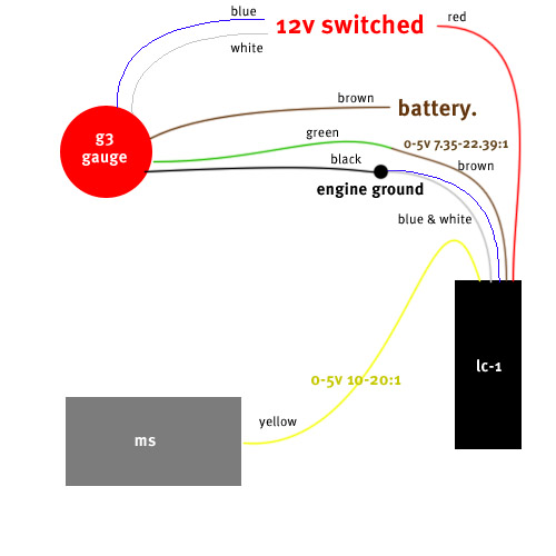
1 difference I have noticed from then wiring diagram is that you have the brown wire form the lc1 going to thje gauge and the yellow going to the ms. I have the brown going to the ms and the green from the gauge going to the brown as well. But I have the yellow taped up and not in use.
Reply
0
0
03-06-2011, 11:15 AM
#14
Boost Czar

iTrader: (62)
Join Date: May 2005
Location: Chantilly, VA
Posts: 79,493
Total Cats: 4,080
brown should go to the MS by default. It's programmed to be the 0-5v 0V = 7.35 AFR and 5V = 22.39. Yellow is narrow band simulation. If you were to calibrate your AFRs to look for a narrowband gauge in Tuner Studio and I bet it looks better
...but you need to switch the two or program them yourself in LMprogrammer.
...but you need to switch the two or program them yourself in LMprogrammer.
Reply
0
0
03-06-2011, 11:23 AM
#15
Junior Member
Thread Starter
Join Date: May 2010
Location: Darlington, UK
Posts: 280
Total Cats: 0
Ok I have tried 2 things.
First I did A calibration by unclipping the sensor and powering the lc1 on then powering off and adding sensor etc. The LED flashed steady for a few secs then went solid indicating all was well but the gauge stayed at 18 and didnt move.
Then I cut the green wire from the gauge and instead of that going to the brown wire which went nto my ECU I connnected the green wire to the yellow of the lc1. This time the same happened except the guage went from 18 whilst the LED was flashing steady on start up to 8 when the LED went solid.
WTF?
Someone please put me out my missery I have spent hours on this pesky thing.
Just seen your post Brain. I didnt want to have to mention this but I cant get the innnovate software to work on my laptop yet. Can I try and avoid using it and still get the gauge to read accuratly foor the time been?
Reply
0
0
03-06-2011, 11:46 AM
#17
Junior Member
Thread Starter
Join Date: May 2010
Location: Darlington, UK
Posts: 280
Total Cats: 0
I have programmed analog 1 so its the same as analog 2. So in theory I can use the yellow wire for the gauge and the brown for the ECU I assume. But still I dont think this will help.
Reply
0
0
03-06-2011, 11:49 AM
#18
Junior Member
Thread Starter
Join Date: May 2010
Location: Darlington, UK
Posts: 280
Total Cats: 0
Well ill eat hay with a donkey. That seems to have the gauge working now. At tickover its flickering around 13.5 to 14. Does that sounds about right?
The gauge registers now which is great but it does seem as if its all over the place when you apply revs and try and keep a constant rev say 3000rpm.
It seems to move very straight towards 18 which is lean. More revs keeps it at 18 and then when I took my foot off back to tick over it wasnt at 13.5 -14 anymore it was more like 16?
Reply
0
0
03-06-2011, 12:19 PM
#20
Junior Member
Thread Starter
Join Date: May 2010
Location: Darlington, UK
Posts: 280
Total Cats: 0
Is the gauge likely to be acurate though? (Meaning do you think it is working now?)
As on Tuner studio the AFR dot on the tables was moving around completly different to what the gauge read?
Plus slightly not related but I think linked. Is the car did seem to run alittle lumpy as if it does need a good tune. If I revd it sometimes the revs would dip quite low and sound as if it was going to stall but not quite.
Reply
0
0


