
NB VSS (Vehicle Speed Sensor) details?

Thread Starter

Joined: Aug 2006
Posts: 3,047
Total Cats: 13
From: San Diego, CA
So I've been all excited to get my shiney new MS3Pro to read in the VSS, apply an arbitrary correction factor (multiplicative or a table I don't yet know) and output to the dashboard. Only, looking at the pin out, I only find a speedometer input on the OEM ECU (for my 2000 model)
A bit more digging, I find this:
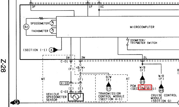
The speedo (aside from going through the trans controller on automatics which I'm not going to consider) appears to be a generator - both sides of which are tied to the dashboard's microcontroller.
Does anyone know how to deal with this, how to make MS3Pro talk to it, etc? I'm assuming I'd need some filtering circuit.
Alternatively, perhaps I could interrupt the signal in the dash itself, to get the processed signal on it's way to the tach, then inject a correct signal afterwards, hoping that this all works out nicely with the signals the MS expects and can put out.
Any thoughts/pointers/etc?
A bit more digging, I find this:
The speedo (aside from going through the trans controller on automatics which I'm not going to consider) appears to be a generator - both sides of which are tied to the dashboard's microcontroller.
Does anyone know how to deal with this, how to make MS3Pro talk to it, etc? I'm assuming I'd need some filtering circuit.
Alternatively, perhaps I could interrupt the signal in the dash itself, to get the processed signal on it's way to the tach, then inject a correct signal afterwards, hoping that this all works out nicely with the signals the MS expects and can put out.
Any thoughts/pointers/etc?
Reply
 0
0

0

Joined: Sep 2005
Posts: 34,409
Total Cats: 7,527
From: Chicago. (The less-murder part.)
It is indeed a "generator." Specifically, a variable-reluctance sensor arranged in a cylindrical package. It outputs an AC waveform which isn't quite a sine-wave, but is close-ish.
I scoped one a few years ago. Here's what the output looks like, measured with a simple single-ended scope probe places across the two wires (the sensor was out of the car at the time):
In this trace I'm turning it just by rolling it across my arm, and it's producing about 5v peak-to-peak.
A simple diode / resistor / zener / comparator circuit would probably be sufficient to produce a squarewave output which could go into the MS (or a MAX9924 if you're feeling saucy.) Coming out of the MS, I'd think you could probably send a squarewave directly into the instrument cluster and have it work. Worst-case you'll need to throw a little 1:1 transformer between the two to produce a floating AC-coupled signal.
Might I ask why you are using the MS3 to re-map the speedometer?
Reply
0
0
Thread Starter
Joined: Aug 2006
Posts: 3,047
Total Cats: 13
From: San Diego, CA
1) OMG! You're leaving?
1b) I thought I was your go-to guy for giving/practically giving me your things
2) Right now I'm thinking of picking up the signal from the dash, but interrupting the internal signal from onboard ("in dash") microcontroller to the actual speedo. This won't mess with the odometer (which is likely not 1:1 with speedo anyway, they rarely are) but should allow me to not have to memorize a new fudge factor every time I change/repressure my tires.
On a recent boring trip through AZ, I found part of it not boring when a cop was riding my bumper for a bit. Thankfully I was able to get my GPS to feed me a correct speed but I thought it would be a hoot if I could get the big orange needle to point at a number representative of my actual velocity. Plus, I'd have been too cheap to buy a new speedo sender with my new rear end, except that it came with one when I got the gears.
Reply
0
0

Thread Starter
Joined: Aug 2006
Posts: 3,047
Total Cats: 13
From: San Diego, CA
Sven,
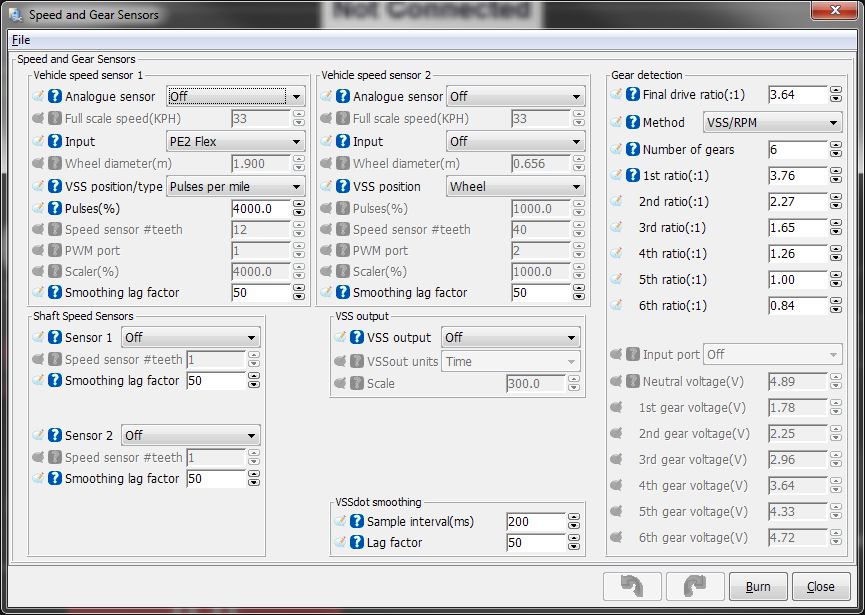
Thanks! Although, that's not what I'm looking for - I'm looking to take advantage of the VSS out feature, to use it as a "speedo-healer" to steal a term from the motorcycle world. To correct the output. Which means I need to know where to pick it up and where to return it.
Thanks! Although, that's not what I'm looking for - I'm looking to take advantage of the VSS out feature, to use it as a "speedo-healer" to steal a term from the motorcycle world. To correct the output. Which means I need to know where to pick it up and where to return it.
Reply
0
0

I thought it was worth bumping this thread to post a follow up.
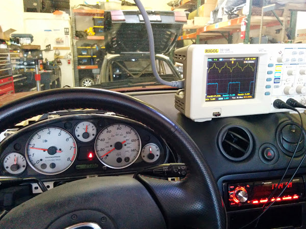
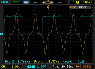
I was curious about the Vehicle Speed Sensor [VSS] output and the speedometer speed output so I put the car on the lift and attached an oscilloscope to the back of the instrument cluster.
I attached CH1 to the output for the VSS, which are pins 2M and 1M.
I attached CH2 to the output of the cluster speedo signal, which is 2L and used the cluster ground 3J.
Here's what I saw:
10mph
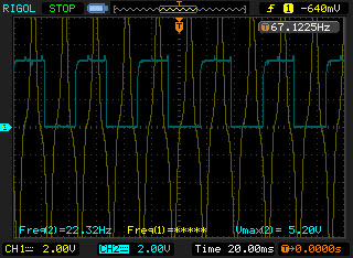
20mph
As you can see, the VSS on CH1 is a variable reluctance [VR] sensor that outputs an ugly 0-centered sawtooth-esque signal. Both the frequency and amplitude of the signal depends on the speed, as is common with a VR sensor. I wouldn't feed this into anything expecting a logic-level signal without something like a MAX9924 in front of it. At high speeds I'd bet it would output north of +50V/-50V.
However, the speed output signal is a nice 5V square wave at half the frequency of the VSS, perfect for triggering just about anything.
Another question I had was the confusion between how many pulses per mile various sensors output and the PCM expected. Online it was reported at both 8000 and 4000 pulses per mile, but people were confusing the various signals and outputs.
At ~10mph, the frequency of the speed output signal is 9.76Hz. This gives 3513 pulses/mile. I suspect its actually closer to 4000 pulses/mile but the low end of the speedo is poorly scaled.
At ~20mph, the frequency of the speed output signal is 22.32Hz. This comes out to 4014 pulses, per mile, so exactly what I had expected.
Since this is half the frequency of the VSS, the instrument cluster expects the VSS output to be 8000 pulses/mile. The VSS goes directly to the cluster and no other components interact with it.
The instrument cluster modifies the dirty VSS signal and outputs a square wave at 4000 pulses/mile that the PCM, Cruise control module, and Bose head unit can read.
Hope this helps someone else!
I was curious about the Vehicle Speed Sensor [VSS] output and the speedometer speed output so I put the car on the lift and attached an oscilloscope to the back of the instrument cluster.
I attached CH1 to the output for the VSS, which are pins 2M and 1M.
I attached CH2 to the output of the cluster speedo signal, which is 2L and used the cluster ground 3J.
Here's what I saw:
10mph
20mph
As you can see, the VSS on CH1 is a variable reluctance [VR] sensor that outputs an ugly 0-centered sawtooth-esque signal. Both the frequency and amplitude of the signal depends on the speed, as is common with a VR sensor. I wouldn't feed this into anything expecting a logic-level signal without something like a MAX9924 in front of it. At high speeds I'd bet it would output north of +50V/-50V.
However, the speed output signal is a nice 5V square wave at half the frequency of the VSS, perfect for triggering just about anything.
Another question I had was the confusion between how many pulses per mile various sensors output and the PCM expected. Online it was reported at both 8000 and 4000 pulses per mile, but people were confusing the various signals and outputs.
At ~10mph, the frequency of the speed output signal is 9.76Hz. This gives 3513 pulses/mile. I suspect its actually closer to 4000 pulses/mile but the low end of the speedo is poorly scaled.
At ~20mph, the frequency of the speed output signal is 22.32Hz. This comes out to 4014 pulses, per mile, so exactly what I had expected.
Since this is half the frequency of the VSS, the instrument cluster expects the VSS output to be 8000 pulses/mile. The VSS goes directly to the cluster and no other components interact with it.
The instrument cluster modifies the dirty VSS signal and outputs a square wave at 4000 pulses/mile that the PCM, Cruise control module, and Bose head unit can read.
Hope this helps someone else!
Last edited by scenturion; May 11, 2014 at 05:56 PM.
Reply
3
3
Joined: Sep 2005
Posts: 34,409
Total Cats: 7,527
From: Chicago. (The less-murder part.)
Glad you were able to solve this, and sorry I wasn't able to give you more data earlier via PM. That's a part of the NB I've never needed to probe.
Nice looking scope, incidentally. Appears to be a clone of a Tek TBS1000, maybe. How are you liking it?
Nice looking scope, incidentally. Appears to be a clone of a Tek TBS1000, maybe. How are you liking it?
Reply
0
0
It's a cheapo Rigol DS1102e. #1 bestselling 'scope on amazon, a coworker and I split it so it ended up being ~$200.
So far so good, it seems to work pretty damn well and its a huge improvement compared to the old CRT scopes I used to use in college
So far so good, it seems to work pretty damn well and its a huge improvement compared to the old CRT scopes I used to use in college
Reply
0
0


Newb
Joined: Feb 2018
Posts: 19
Total Cats: 0
This seems like the right thread with the right people in it so I'm going to give it a shot:
I removed the stock dash cluster and have a question regarding VR conditioning and the outputs of the NB VSS sensor. Since I don't have the dash conditioning the VSS signal anymore, I bought one of these nifty VR conditioners from DIYAUTOTUNE to get the signal properly converted for my MS3PRO PNP (note: I believe the PNP version does not have any VR conditioning inputs like the non-PNP PRO) .
https://www.diyautotune.com/product/...tioner-module/
But I'm confused on what signals go to the "VR sensor +" and "VR sensor -" inputs on the conditioning board. It appears on the wiring diagram for the NB that the VSS has two wires(Y and O): One goes to the dash and the other the AT control module. So does that mean they are both signal so I can use either to connect to "VR sensor +" and don't connect anything to the "VR sensor -"???
Thanks for any help
Reply
0
0
You need to hook both wires up to the VR conditioner. It does not matter which wire is the+ or -. After that I don't know. Never used that conditioner with a MS before.
Reply
0
0

Newb
Joined: Oct 2020
Posts: 16
Total Cats: 4
From: Ribe, Denmark / aka. The Sticks
The DIYAutoTune looks like the thing I need to stick between my stock NB VSS and the Sinco D0908 dash I'm putting in - and while I don't mind paying US$ 70 for a gizmo, I go into complete meltdown when I have to pay the same for shipping to Denmark ( : I then stumbled over the Speeduino VS Conditioners which, as far as I can tell, does exactly the same:
Speeduino Assembled Dual VR Conditioner V3 – DIY-EFI
Any reason this shouldn't work?
Thank you!
Speeduino Assembled Dual VR Conditioner V3 – DIY-EFI
Any reason this shouldn't work?
Thank you!
Reply
0
0

Newb
Joined: Apr 2024
Posts: 7
Total Cats: 0
From: Cologne, Germany
Hey guys,
I know this thread is oooooold but for me it is currently the only trace I have.
Im trying to build a hybrid dash and therefore need to read all data (RPM, Speed etc.) from the back of the cluster. I bought a signal generator and hooked it up to the ports of the VSS. This works fine and I can generate a sine wave and control the speedometer. My problem is that there is no output on 2L. I hooked my oscilloscope on 2L and 3J but Im getting nothing (except random nonsense).
Any ideas why?
Thanks!
Reply
0
0

Newb
Joined: Oct 2020
Posts: 16
Total Cats: 4
From: Ribe, Denmark / aka. The Sticks
The DIYAutoTune looks like the thing I need to stick between my stock NB VSS and the Sinco D0908 dash I'm putting in - and while I don't mind paying US$ 70 for a gizmo, I go into complete meltdown when I have to pay the same for shipping to Denmark ( : I then stumbled over the Speeduino VS Conditioners which, as far as I can tell, does exactly the same:
Speeduino Assembled Dual VR Conditioner V3 � DIY-EFI
Any reason this shouldn't work?
Thank you!
Speeduino Assembled Dual VR Conditioner V3 � DIY-EFI
Any reason this shouldn't work?
Thank you!
Anyway - I jumped the gun on above and the Speeduino VR conditioner was indeed just what the doctor ordered. It works perfectly sitting between the VSS and the Sinco dash (which has been faultless - can't beat it for the price). It's getting replaced though with a Powertune Digital Dash V5 - because racecar and datalogging and speedo/brake overlay for the GoPro videos

Reply
0
0


