OEM 36-1 Wheel
 05-10-2012, 04:19 PM
#21

The sensor you are using may be a VR and Not a hall effect sensor, I was working with Joe in this thread of what needs to be done to use a VR sensor
https://www.miataturbo.net/megasquirt-18/looking-ms1-settings-36-1-trigger-65675/
Or as it seems you can use an OE NB sensor and use the same hall effect circuit already built for the CAS.
https://www.miataturbo.net/megasquirt-18/looking-ms1-settings-36-1-trigger-65675/
Or as it seems you can use an OE NB sensor and use the same hall effect circuit already built for the CAS.

Reply
 0
0

0
05-10-2012, 05:41 PM
#22
Boost Pope


iTrader: (8)
Join Date: Sep 2005
Location: Chicago. (The less-murder part.)
Posts: 33,027
Total Cats: 6,593
If you're asking whether the sensor itself was damaged by the application of +5v? Probably not. I've never measured the resistance of a VR sensor's coil, but I assume it's high enough to prevent a significant amount of current from flowing through it, especially if the other side was not grounded.
Reply
0
0
05-14-2012, 08:27 AM
#23

Joe, I ment that with cranking speeds I presumed no harm to Megasquirt.
No power was turned on to the sensor. I wired black and white wires from DIY autotune harness into respectively green and red ones in the sensor. The shielding ground was connected to signal ground, but I think it might be better to ground it to engine block instead, at least in theory.
Car starts and idles with sequential ignition and injection. The gap between sensor and wheel needs to be checked when changing the wheel, the od appears to be the same, but in my case there were slight contact between wheel and the sensor at some teeth. Also the sensor is pretty sensitive, it will not see the targets if there is nmore than 2 mm gap.
So for ~$20 wheel you can get the resolution you want with factory parts and no bracket or wheel design and fabrication needed. I presume it will work as long term solution as well as the stock one. My sensor is quite probably original from -96.
hrk
Reply
0
0


 02-08-2013, 12:43 PM
#31
Elite Member
iTrader: (16)

Join Date: Oct 2006
Location: Las Cruces, NM
Posts: 1,647
Total Cats: 524
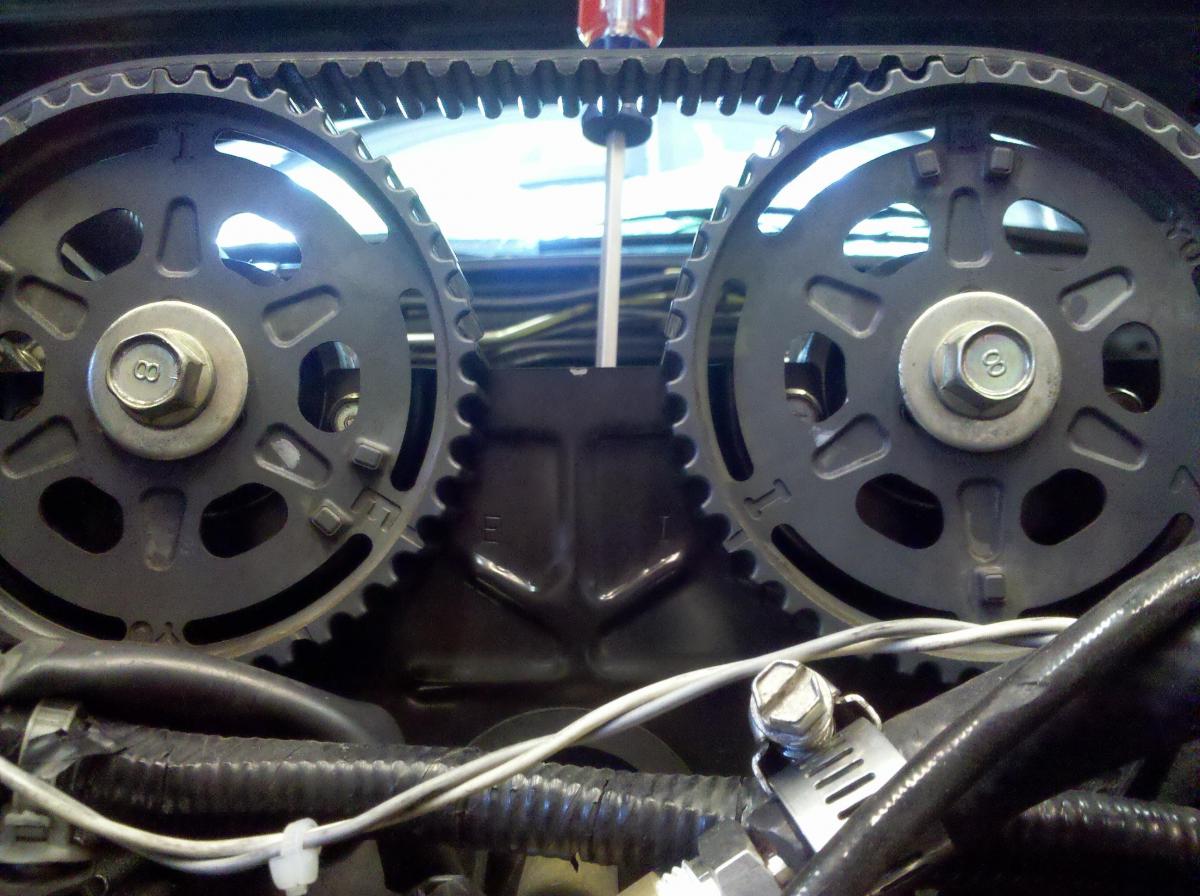
Thanks to from Soviet and Reverant about the cam sensor mods required to do this on an NB. To use this trigger wheel you need to grind off the dual sensor nubs by the "E" on the cam pulley. You also have to make sure that the cam pulley sensor the cam sensor is NOT over (or very near!) the single cam tooth on the cam wheel when the crank sensor is over the missing tooth on the 36-1 wheel. The crank trigger wheel can only be installed one way but the cam pulley can be positioned in three different positions on the cam.
Has anyone with an NB tried this mod and repositioned the cam pulley? If so, how was the cam pulley placed and what settings in MS are required?
Has anyone with an NB tried this mod and repositioned the cam pulley? If so, how was the cam pulley placed and what settings in MS are required?
Reply
0
0
02-12-2013, 09:11 PM
#34
Wiggy. I guess it's all in the decoding, then? Cause, anything like that would make VVT more annoying. I guess not crazy, but grinding the cam feels.... permanent.
Think I'll be playing with this one later, in a couple months, when I gotta figure out how to support both VVT and 36-1.
Think I'll be playing with this one later, in a couple months, when I gotta figure out how to support both VVT and 36-1.
Reply
0
0
04-16-2013, 05:44 AM
#35
Junior Member

Join Date: Oct 2009
Location: The Netherlands
Posts: 200
Total Cats: 1
I ordered this part.
Somehow I cannot get it to fit.
The wheel interferes with the plastic TDC reference point. That can be trimmed though.
Also the dished out part is not deep enough for my pulley. There is a gap between the wheel and the balancer. Quite a big gap. The wheel runs into the rubber part of the balancer, but even with that trimmed out, here is not enough room to get it to fit. How on earth did you get that wheel on the stock balancer ?
I think you have to use the later style balancer to get it right. To make it perfect, is there a way to upgrade the whole belt assembly to serpentine on the big nose B6 engine ? What parts are involved ? It would be nice to swap the alternator pulley, the waterpump pulley and the cranckshaft pulley to serpentine + ability to fit the triggerwheel. This would be the ultimate upgrade.
Last edited by IHI; 04-18-2013 at 04:26 PM.
Reply
0
0
08-19-2013, 07:09 AM
#36
Senior Member

Join Date: Dec 2004
Location: Brisbane, Australia
Posts: 1,278
Total Cats: 37
I have measured this wheel and the OE NB wheel, here are the angles:
Crank sensor is mounted at 110 degrees.
OE crank trigger plate:
First tooth is at 190 degrees on plate, so triggered 80 degrees BTDC
Second tooth is at 120 degrees on plate, so triggered 10 degrees BTDC
Per 180 degree period:
80,10
Protege 36-1 trigger plate:
First tooth is at 190 degrees on plate, so triggered 80 degrees BTDC
Second tooth is at 180 degrees on plate, so triggered 70 degrees BTDC
...
Per 180 degree period:
80,70,60,50,40,30,20,10,0,170,160,150,140,130,120, 110,100,90 (90 missing on 2nd period for reset)
The OE wheel has teeth that are 1 degree wide, and on the Protege wheel they are 3 degrees wide. With my ECU I trigger on the trailing edge of the tooth, so it will be 2 degrees out unless adjusted.
Reply
1
1
10-20-2013, 05:41 AM
#37
Junior Member

Join Date: Jun 2013
Posts: 115
Total Cats: 1
Would fitting one of these allow one to just use a single crank angle input with wasted spark without the cam position input. Making ms easier to set up and also preventing timing from being effected by cam belt stretch etc. Would this bolt onto a 1.8 bp engine?
Reply
0
0
10-20-2013, 06:31 AM
#38
Elite Member
iTrader: (10)
Join Date: Jun 2006
Location: Athens, Greece
Posts: 5,977
Total Cats: 356
Timing is not affected by cam belt stretch, as the cam sensor (as used on the 99-005) is only there to tell the ECU the current cylinder phasing, and not the crank angle.
Without a cam sensor, you can't run sequential injection or ignition.
Without a cam sensor, you can't run sequential injection or ignition.
Reply
0
0
10-20-2013, 08:26 AM
#39
Junior Member
Join Date: Jun 2013
Posts: 115
Total Cats: 1
Is there any real world benefit to running sequential injection and ignition. I'm halfway through building my MS2 and its my first foray into electronics so any thing that makes it simpler is a good thing. Also I have a standard stim not jim stim
Reply
0
0


