
3d printed intake for N/A NA miatas
 11-29-2015, 06:40 PM
#263
You can do wet sanding with a dremel however you need the flex extension tool. You dont want liquids splashing on the dremel.
After you're done, you can just donk the flex head in oil to get rid of the water. When doing this you want to use gravity to your advantage. Tie the dremel up high so the flex extension is pretty straight and pointing. You can also find them in stainless steel.
After you're done, you can just donk the flex head in oil to get rid of the water. When doing this you want to use gravity to your advantage. Tie the dremel up high so the flex extension is pretty straight and pointing. You can also find them in stainless steel.

Reply
 0
0

0
11-30-2015, 01:53 PM
#264
Newb

Join Date: Oct 2015
Location: Hamilton, Ontario, Canada
Posts: 33
Total Cats: 4
Can you not use an inflatable bladder in conjunction with a vacuum to make seamless hollow parts? They could come out of the mold needing just minor trimming instead of machine work and assembly.
I would think a cut inner tube clamped onto hard cap ends. You wouldn't even need much pressure with the help of the vacuum.
I would think a cut inner tube clamped onto hard cap ends. You wouldn't even need much pressure with the help of the vacuum.
Last edited by Eunn; 11-30-2015 at 02:18 PM.
Reply
0
0
11-30-2015, 02:17 PM
#265
Senior Member

Thread Starter
iTrader: (1)

Join Date: Jul 2012
Location: durham NC
Posts: 792
Total Cats: 143
Yes and no. Bladders were my original plan but after doing a ton of reading about them I haven't found a cost effective and reliable way to make ones that would work well with these compound curves. Similarly, I can easily make tubular vacuum bags which would allow for the two halves to be done together.
The problem is that the part diameter is so small, and I am working with wet layup for cost reasons (anyone want a $400 pre-preg duct?) which is inherently messier than pre-preg, I can't get in there to manipulate flaps of carbon fiber, peel ply, breather fabric... The stack becomes unmanageable in that small of a space. The other issue, removing the bagging stack from inside the part would be close to impossible. I have a bunch of tools coming that should make this easier. I also dug out my drum sanding kit for the drill press. Long term, carbon dust will kill anything electric but bench top drill presses are cheap enough on craigslist.
The problem is that the part diameter is so small, and I am working with wet layup for cost reasons (anyone want a $400 pre-preg duct?) which is inherently messier than pre-preg, I can't get in there to manipulate flaps of carbon fiber, peel ply, breather fabric... The stack becomes unmanageable in that small of a space. The other issue, removing the bagging stack from inside the part would be close to impossible. I have a bunch of tools coming that should make this easier. I also dug out my drum sanding kit for the drill press. Long term, carbon dust will kill anything electric but bench top drill presses are cheap enough on craigslist.
Reply
0
0
11-30-2015, 02:40 PM
#266
Newb
Join Date: Oct 2015
Location: Hamilton, Ontario, Canada
Posts: 33
Total Cats: 4
Ah this is true. I guess the CF would be all greasy and siding around and you won't see it until after. Is dry layup possible without pre preg by drawing the resin into the mold with the vacuum pump?
Reply
0
0
11-30-2015, 05:09 PM
#267
Senior Member
Thread Starter
iTrader: (1)
Join Date: Jul 2012
Location: durham NC
Posts: 792
Total Cats: 143
The drum sanding attachment takes out material fast, but sometimes its grabs and takes it out too fast. I am considering this my **** up part, so if it doesn't end up being pretty im not going to worry too much. A few places are over trimmed and have a gap. I will end up running a 1/2" carbon tape along the whole joint in this case.
In the future, aggressive tool for 70% of the work, then switch to hand tool for last bit.
In the future, aggressive tool for 70% of the work, then switch to hand tool for last bit.
Reply
0
0
11-30-2015, 05:12 PM
#268
Boost Pope

iTrader: (8)
Join Date: Sep 2005
Location: Chicago. (The less-murder part.)
Posts: 33,049
Total Cats: 6,608
Just out of curiosity, and apologies if you covered this earlier, but how will the two halves of the part be joined?
Also, the inside looks very nice. I don't see any wrinkles from the bag at all. Not too shabby for a wet-layup part.
Reminds me of:

Also, the inside looks very nice. I don't see any wrinkles from the bag at all. Not too shabby for a wet-layup part.
Reminds me of:
Reply
0
0
 11-30-2015, 05:37 PM
#270
Senior Member
Thread Starter
iTrader: (1)
Join Date: Jul 2012
Location: durham NC
Posts: 792
Total Cats: 143
The two halves will be joined with a high quality structural epoxy. I am going to put the parts back in the molds, and then place the molds together (they have registration indents) and use a dab of epoxy in all 4 corners to 'tack' everything in place. This part is going to get a 1/2" strip of thin unidirectional carbon tape laminated over the joint for increased strength and to not look shitty. If I can get the trimming down to a more exact process I won't need to do that. I think the whole trimmed line needs to be +/- .5mm per side for a maximum of 1mm bond gap for me to not want to use the tape. Also, the next time I run out of structural epoxy I will get some that is black so it isn't as visible in the joint.
Also, the part will get heavier, and the weight doesn't really matter- It is currently 101 grams. Eerily light in my hand. The total weight right for both elbows, carbon crossover, iat, and filter and duct is now 1.8lb. Stock intake is 6lb.
Also, the part will get heavier, and the weight doesn't really matter- It is currently 101 grams. Eerily light in my hand. The total weight right for both elbows, carbon crossover, iat, and filter and duct is now 1.8lb. Stock intake is 6lb.
Last edited by asmasm; 11-30-2015 at 05:58 PM.
Reply
0
0
11-30-2015, 06:05 PM
#271
Senior Member
Thread Starter
iTrader: (1)
Join Date: Jul 2012
Location: durham NC
Posts: 792
Total Cats: 143
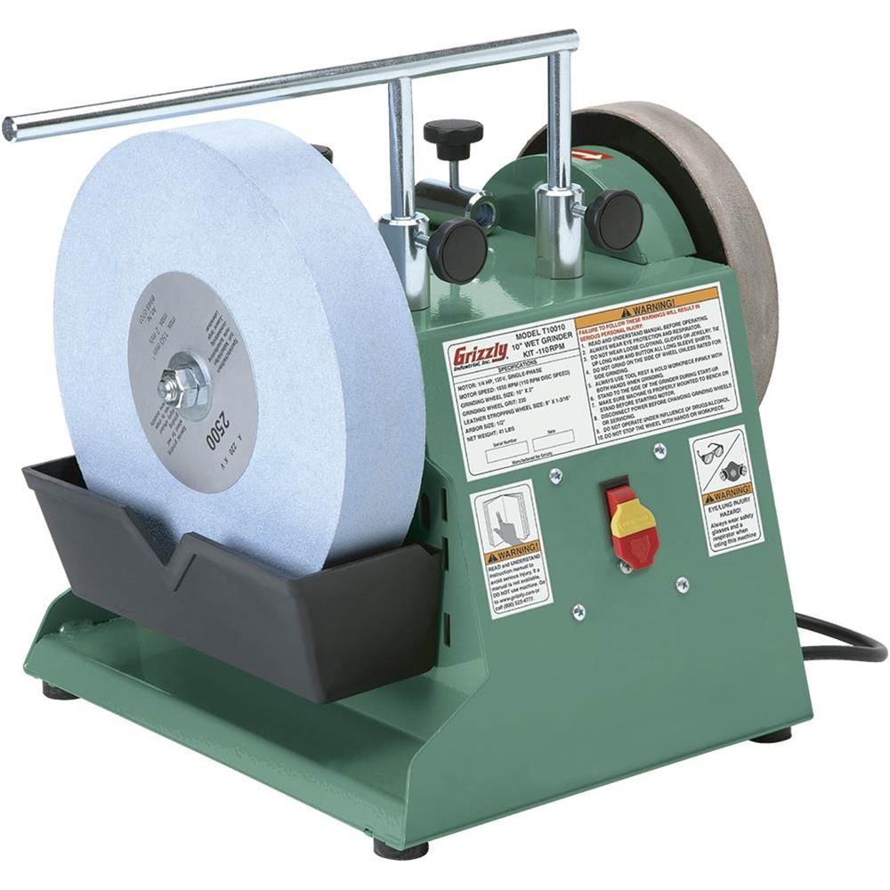
Also, I have been trying to figure out the temp controller for my oven. This is probably the least complicated page in the manual:
https://i.imgur.com/RdHW1NH.png
It does up to 50 segments, which is great except that you have like 3 buttons to program it with. Ideally, it will run at 70f for an hour (allow resin to flow), an hour at 80, 90, 100, hold at 110. Then post cure the final parts at like 180 with a slow ramp.
https://i.imgur.com/RdHW1NH.png
It does up to 50 segments, which is great except that you have like 3 buttons to program it with. Ideally, it will run at 70f for an hour (allow resin to flow), an hour at 80, 90, 100, hold at 110. Then post cure the final parts at like 180 with a slow ramp.
Reply
0
0
12-01-2015, 01:18 PM
#272
Senior Member
Thread Starter
iTrader: (1)
Join Date: Jul 2012
Location: durham NC
Posts: 792
Total Cats: 143
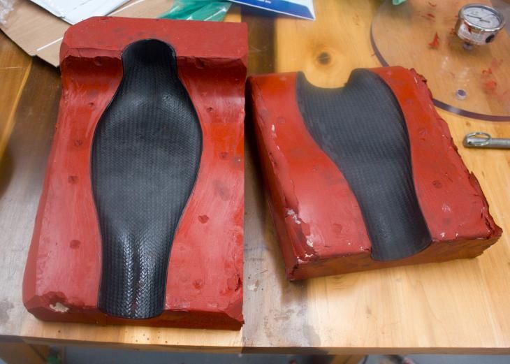
Both sides tacked together. This this the better of the two edges. I have some higher viscosity epoxy coming that will fill the gap. I am also going to laminate 1/2 along the edge and around both the tube ends. Using the molds to get the two parts aligned works great- I can make sure I have the correct geometry even if I over trim.
Reply
0
0
12-01-2015, 05:05 PM
#273
Senior Member
Thread Starter
iTrader: (1)
Join Date: Jul 2012
Location: durham NC
Posts: 792
Total Cats: 143
I am starting a preliminary list of people who want carbon intakes. If you are interested send me an email at: durhamcomposite@gmail.com and we can talk details.
Reply
0
0
12-01-2015, 05:09 PM
#274

I am starting a preliminary list of people who want carbon intakes. If you are interested send me an email at: durhamcomposite@gmail.com and we can talk details.
Reply
0
0
12-02-2015, 03:51 PM
#275

Hey so i've been following this for quite awhile now, glad to see where its going! You will receive an email shortly, but I believe these questions may useful to others as well..
On page 3 you show a "breakdown of parts needed" which is appreciated but I do have some concerns
-First is the hose nearest to the throttle body which you say requires 3/4" hose barb at 90*, i am assuming the other end is 1/2" NPT to fit the Silicone Intakes port system, which is SOLD OUT?!11!!
I have yet to find a 3/4" barb -> 1/2" NPT in 90* except for one I did find on eBay, nothing on SI.com.
More importantly i thought our IAT's had a 3/8 NPT fitting which is not what the SI port system gives you, its 1/2"... so on that note:
-Any update on your custom iat bung/port you were making? (page 12)
-Also, I'm confused on the solution for those running stock TB... seems like 2.5"(63.5mm), the ideal size, is only ideal with a 64mm skunk2. Or is the reducing elbow (2.5"->2.75") a good fit for the stock TB? I just need to be sure, lol.
Thanks Alec!
Reply
0
0
12-02-2015, 07:47 PM
#276
Senior Member
Thread Starter
iTrader: (1)
Join Date: Jul 2012
Location: durham NC
Posts: 792
Total Cats: 143
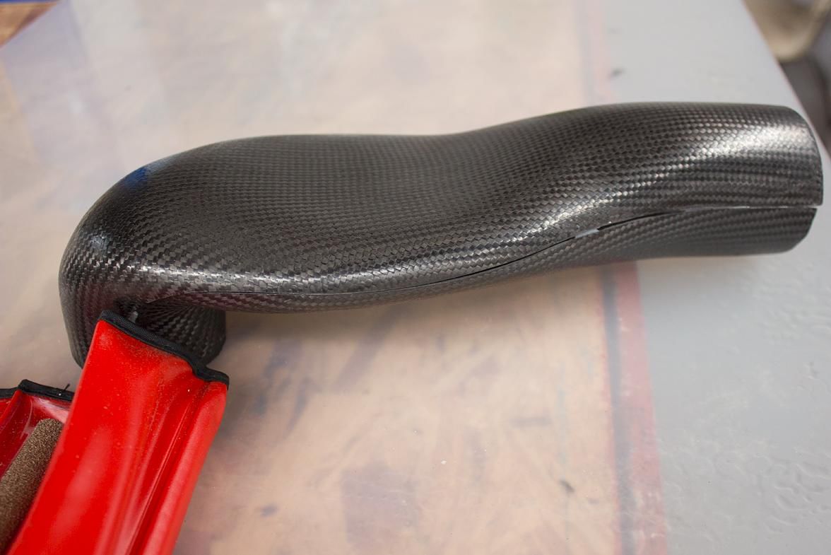
Halves bonded with hysol 1c. I applied it almost like a body filler so it is feathered into some minor low spots as well. In the future, I will tint it black so it doesn't look as bad. Also, this will be covered with a carbon strip:
Last edited by asmasm; 12-02-2015 at 08:51 PM.
Reply
0
0
 12-04-2015, 07:39 PM
#279
Senior Member
Thread Starter
iTrader: (1)
Join Date: Jul 2012
Location: durham NC
Posts: 792
Total Cats: 143
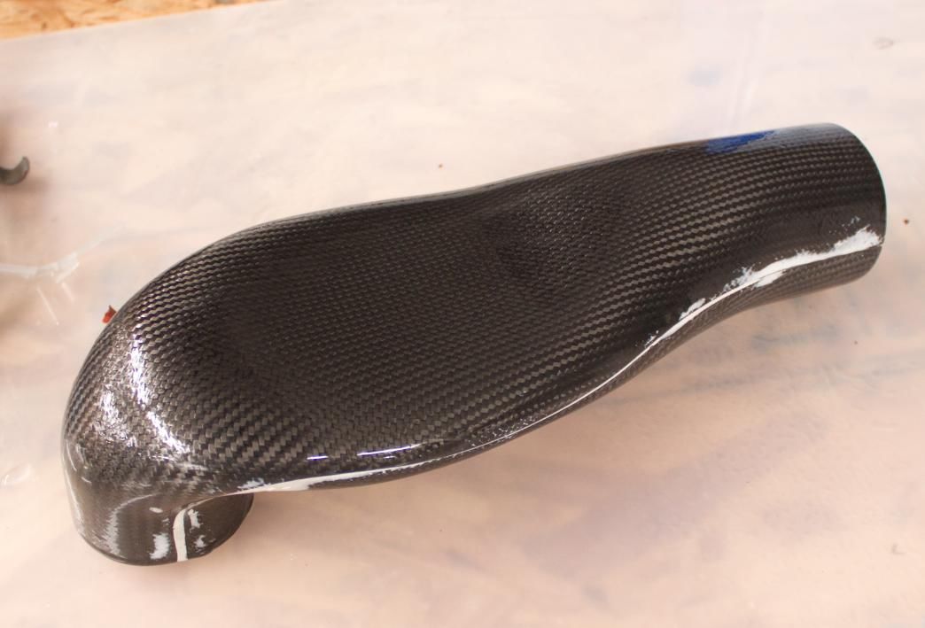
I laminated strips over the joint to make it stronger and look better. Also shot it quick coat of clear over it for UV protection. If I wanted this to make this look really nice I would wet sand and polish the clear (or just make sure the part was 100% clean before spraying).

Reply
0
0


