When you click on links to various merchants on this site and make a purchase, this can result in this site earning a commission. Affiliate programs and affiliations include, but are not limited to, the eBay Partner Network.
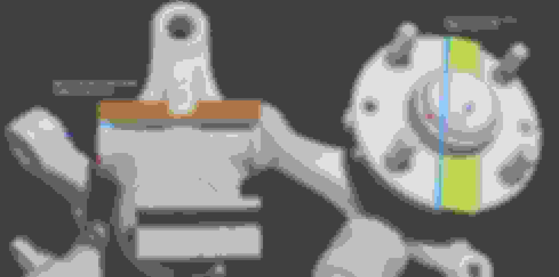
I think this is a very good result for accuracy. I'm using cheap harbor freight calipers and my method for measuring on the model is not super precise. If I had better calipers I could take 4-5 measurements and try and find a trend for what % difference between model and real, then apply that scale factor. Either way, this is damn close:
The differences are 0.10015% and 0.065822%. Assuming a .1% error over a 600mm span the error would be .6mm.
Error is completely application depended, making a set of brake ducts with this scan and the accuracy is overkill. Try to use this scan to make an adapter plate to locate a transmission bolt pattern and .060" error is enough you'll never get it bolted together let alone concentric enough to the output shaft to run for any length of time.
Error is completely application depended, making a set of brake ducts with this scan and the accuracy is overkill. Try to use this scan to make an adapter plate to locate a transmission bolt pattern and .0024" error is enough possibly have issues with the output shaft being too far out of center.
Correct. The usefulness of the scans is application dependent. The transmission bell housing bolts are probably closer to 400mm apart than 600 so the error in the case would be lower. Still too large. For really critical dimensions that scans can be adjusted to fit real world measurements.
What I'm imagining is not just individual parts scans but most of the car in an assembly that can be loaded piece by piece. This would allow people to design for part fit on the specific mounting locations and also for interference for within the whole assembly/car. Also things like body modifications and aero templates generally rely on tracing cardboard templates and iterative fitting.
I remember trying the Kinect thing in college, but if memory serves me correct, the dimensions were so inaccurate that they could not be used. We ended up using a local company's Faro arm instead.
Here is the paper I read, the results looks pretty good. Sadly I don't have access to MatLab to test out their code
Okay, another lesson learned. Process the mesh at the highest resolution possible then chop the result down. The cleaner mesh here is actually lower triangle count after reduction. The mesh I posted before (the lower quality one in this gif) took about 45 minutes to process. The new one had to run overnight:
Organic objects like body panels, interior pieces, some suspension components, etc are a great fit for this, but for more technically built pieces, the deck of the engine block for instance, I think would be better modeled with actual blueprints/dimensioned sketches.
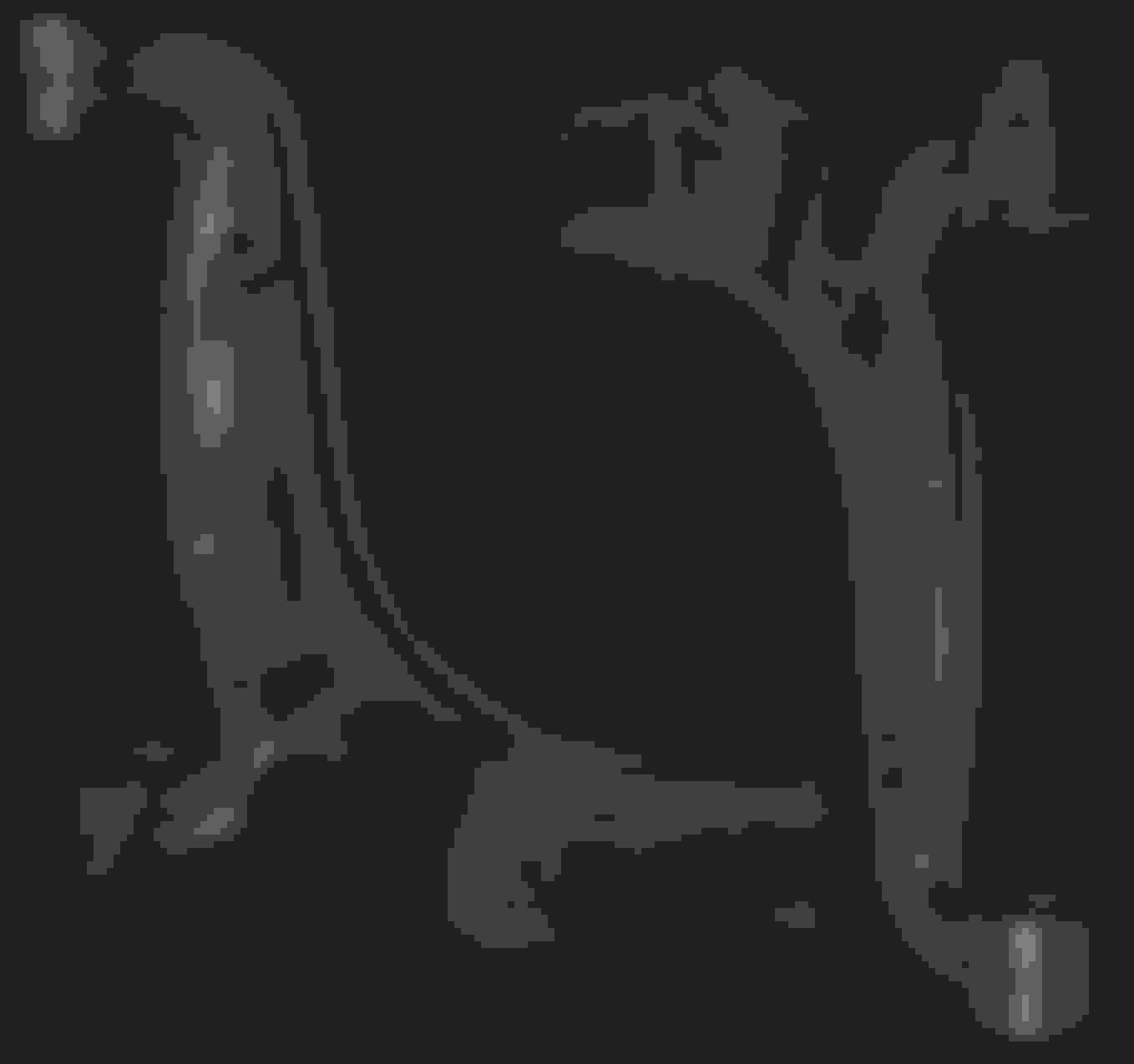
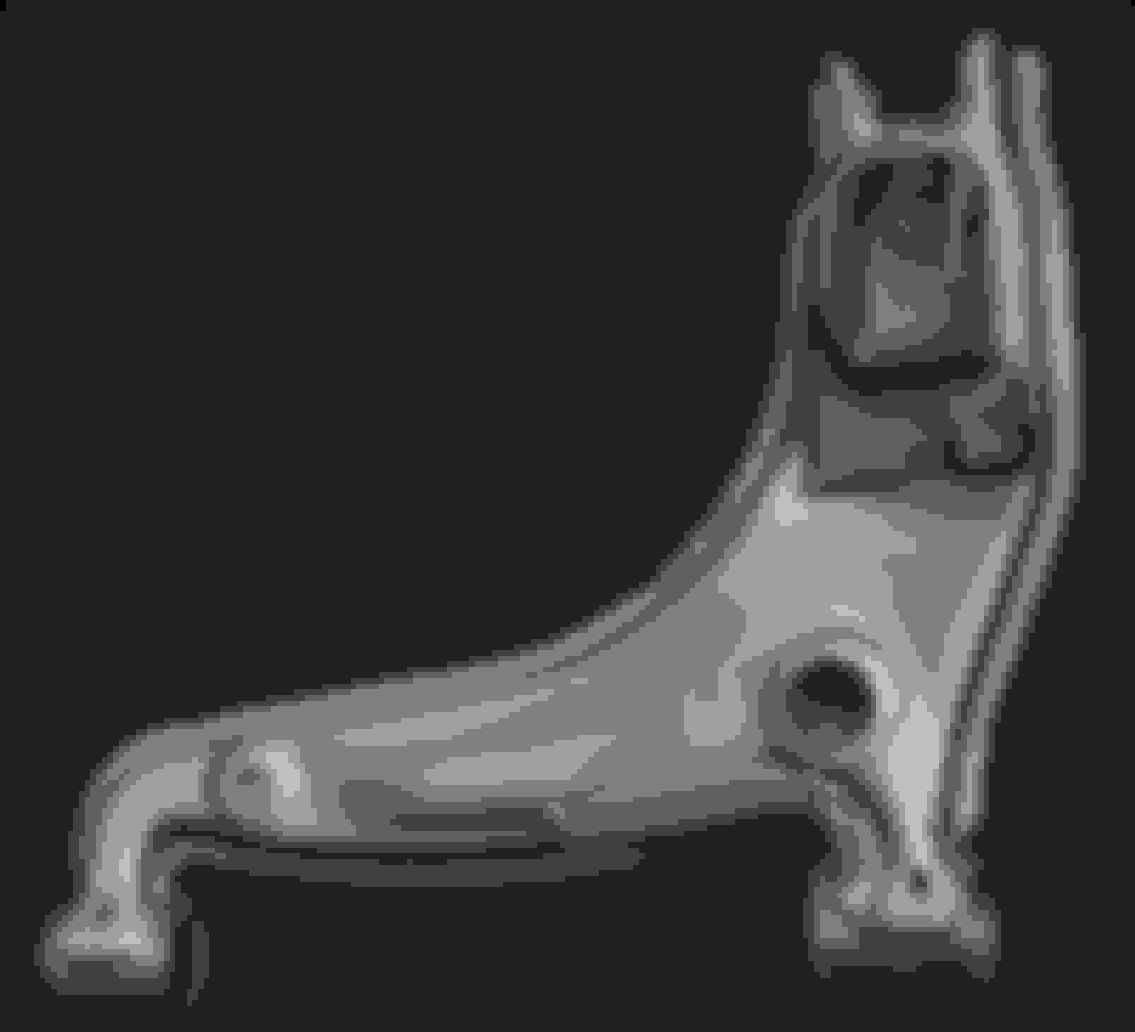
Example: suspension arms would have to be cleaned up and bushing holes would have to be simplified and dimensioned, as well as smoothing out ALL that casting flash.
The reason for this is because your object doesn't have any planar faces or cylinders to base an origin reference from. This is something that is needed when assembling components together in a program like Solidworks.
My point is that these parts would need further modification to be used in the intended computer application.
For example, imagine wanting to machine a billet aluminum UCA from the exact dimensions of the cast original using these models.
The operations would go as follows (for Solidworks at least, since it's what I use)
simplify polygons
assuming an edge is not generated somewhere automatically, spend a bunch of time setting the edge on the flattest face you can in order to get the correct origin of part.
create planes and sketches outlining and dimension all circular and flat faces
extrude cut all the bushing holes and dimension them.
"shave" away all flashing from the cast part
FEA test the part in whatever material you will make it from
send to CNC
I think this is worth pursuing, but I fear it would be time intensive for people wanting to modify and fabricate parts based off them. My only real concern for the usability of these scans are in getting the surfaces acquired.
If it takes me hours just to pin down a flat surface it wont be worth my time since I could just take measurements from the part with a ruler and tools in the same amount of time.
If you post a file, that control arm for instance, I could play around with it and report back
I hear what you are saying with finding reference surfaces on a dense polygon model but the usage example doesn't make a lot of sense to me. I can't see anyone looking to CNC a copy of an OEM steel piece in aluminum by directly cleaning up scan data.
I can align the model's orientation and placement in the scan software. Generally the scans should be treated like physical objects to take measurements from. Again, I think the advantage here would be having a complete assembly to work with. It would drastically reduce the number of oops moments where a prototype interferes with another part in an unforeseen way and it allows for designing in areas where there is limited space to route a part.
I got one of these einscan-s-3d-scanner at work for scanning architectural elements (primarily stone) so we can recreate them with a variety of technologies. Never thought of using it for scanning OEM parts is a pretty neat idea. It does take some time to scan the object in, especially if you have to rig it up to scan it (better if the object rotates at a set distance from the scanner as opposed to moving the scanner around the object). would really love to scan the whole car so you can play with custom aero bits without having the fabricate. So much technology now with simulating aerodynamics is so cool!
Ok maybe the control arm was a bad example, but my concern still stands about what kind of process and programs this assembling you are thinking of will take place in.
I fear these scans are going to be way too large to play with in any CAD program unless they are cleaned up or simplified to the point where touch up will indeed be required.
It would be nice to post a test scan of something. Anything really. A pipe with threads for example.
My PC is on the top end of what people use/have access to. I would like to see if this is even possible to load something this complex and successfully edit it in the way I am trying to convey.
My shitty work computer can open the stl without issues.
Xenon processor, 16 gigs of ram, and a crappy Quadro card.
My dinosaur of a home computer opened the file up without issues.
i5 4790k, 16gigs of ram, gtx970
Cleaning up the scans would help with load times if you're trying to clean it up in a cad program. Load times and editing in MeshLab (or a similar program) is a lot faster.
I don't know how this thing works, but could you use it to finally get a real model of the bottom of the miata? This could then be used for cfd work, if it's that easy. In my head it sure is simple.
I use an artec spider 3D scanner at work along with polyworks to create a functional part model.
We, as a community, should definitely build a library!
Just as an update- I am still scanning parts and I plan to post the first set of scans soon. Also, I wanted to share the primary purpose of the scans and hopefully get some help tracking down cheap parts for me to continue. I am working towards building a VR game where you can completely disassemble an NA (gameplay would probably involve diagnosing and fixing). Imagine walking around a small car with a room scale VR setup, flashlight in one hand, and multi-tool in the other. My first goal (hopefully within a month) is the completed front suspension corner sitting on the front sub frame. After that I will move onto the rear suspension, then all the drive train parts. I expect I can have the roller skate finished in about 6 months.
I have been buying some used parts but this is getting expensive. If anyone has junk stock parts they are willing to part with please let me know. I am currently looking for:
Stock shock + spring (or bilsteins)- I only need one front and one rear
Front subframe
5 speed transmission
Rear Subframe
Rear upright and hub
A 1.8 diff with housing.
If you are local I can scan a part in a weekend and return it thoroughly cleaned.
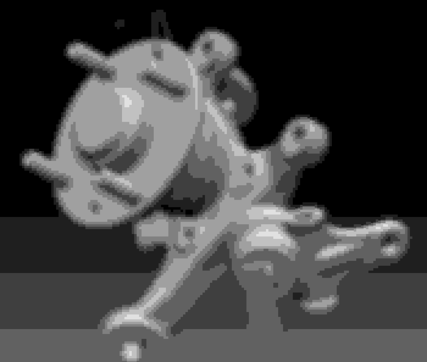
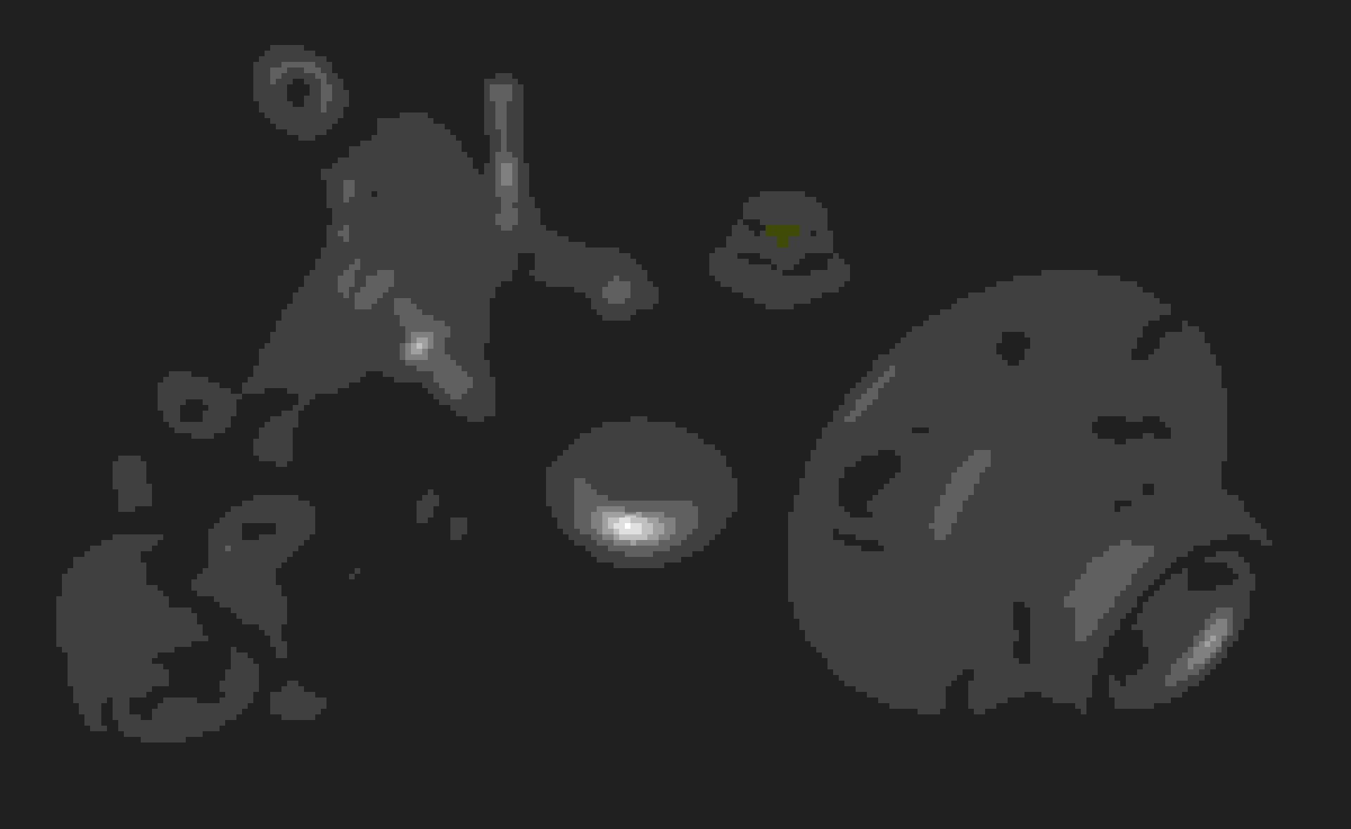
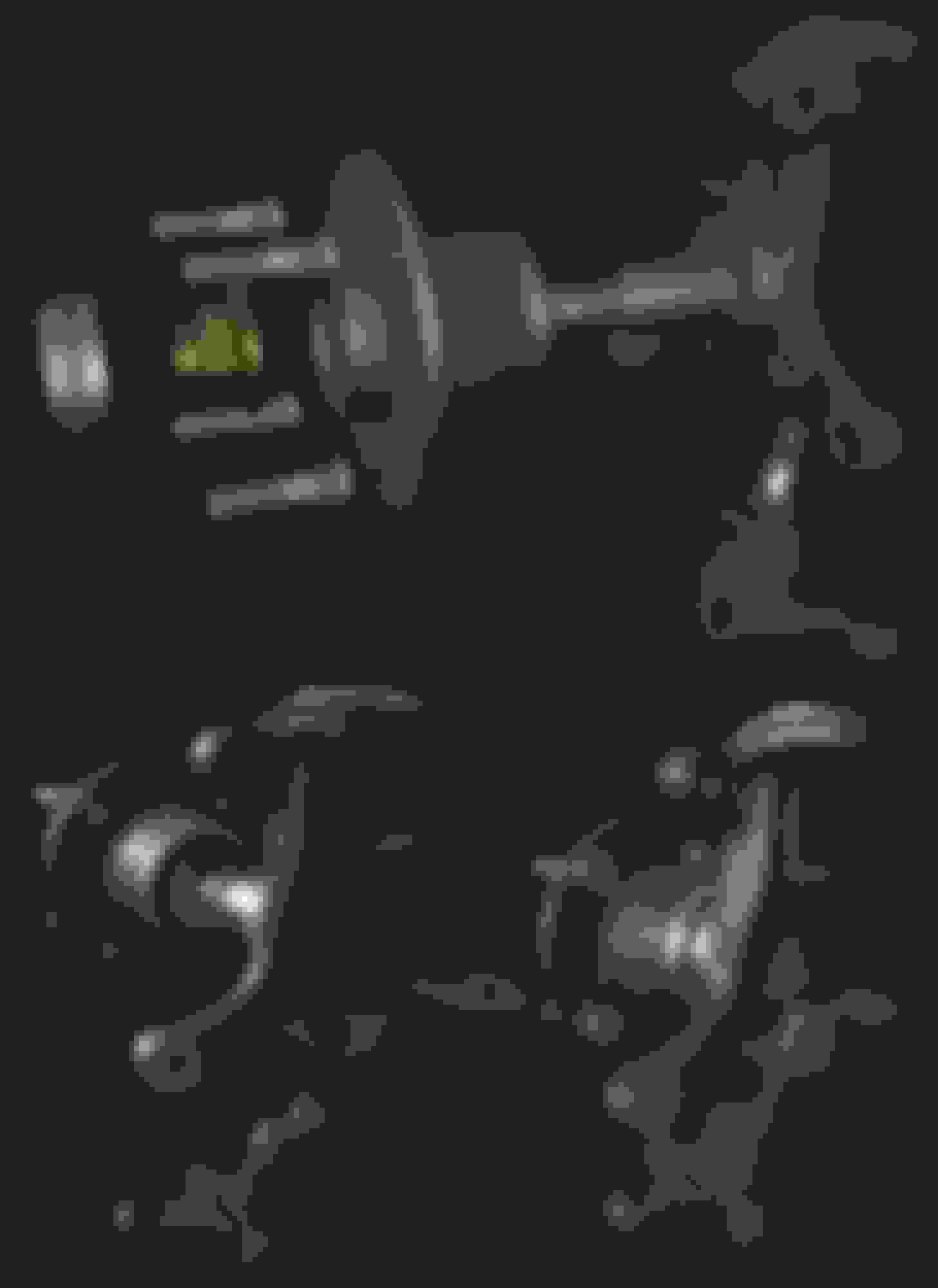
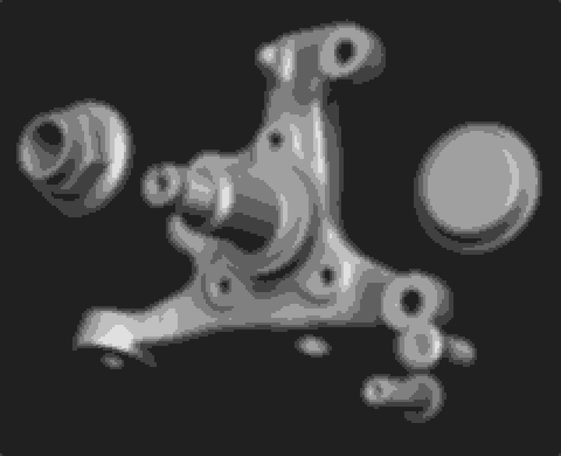
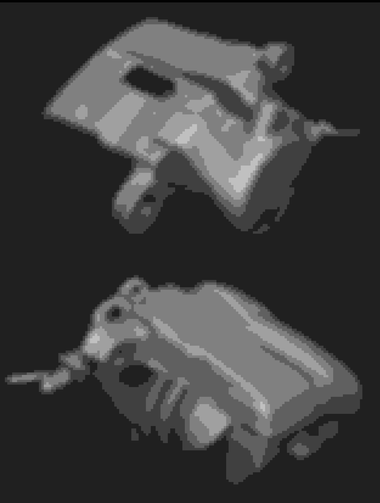
First few game ready assets:
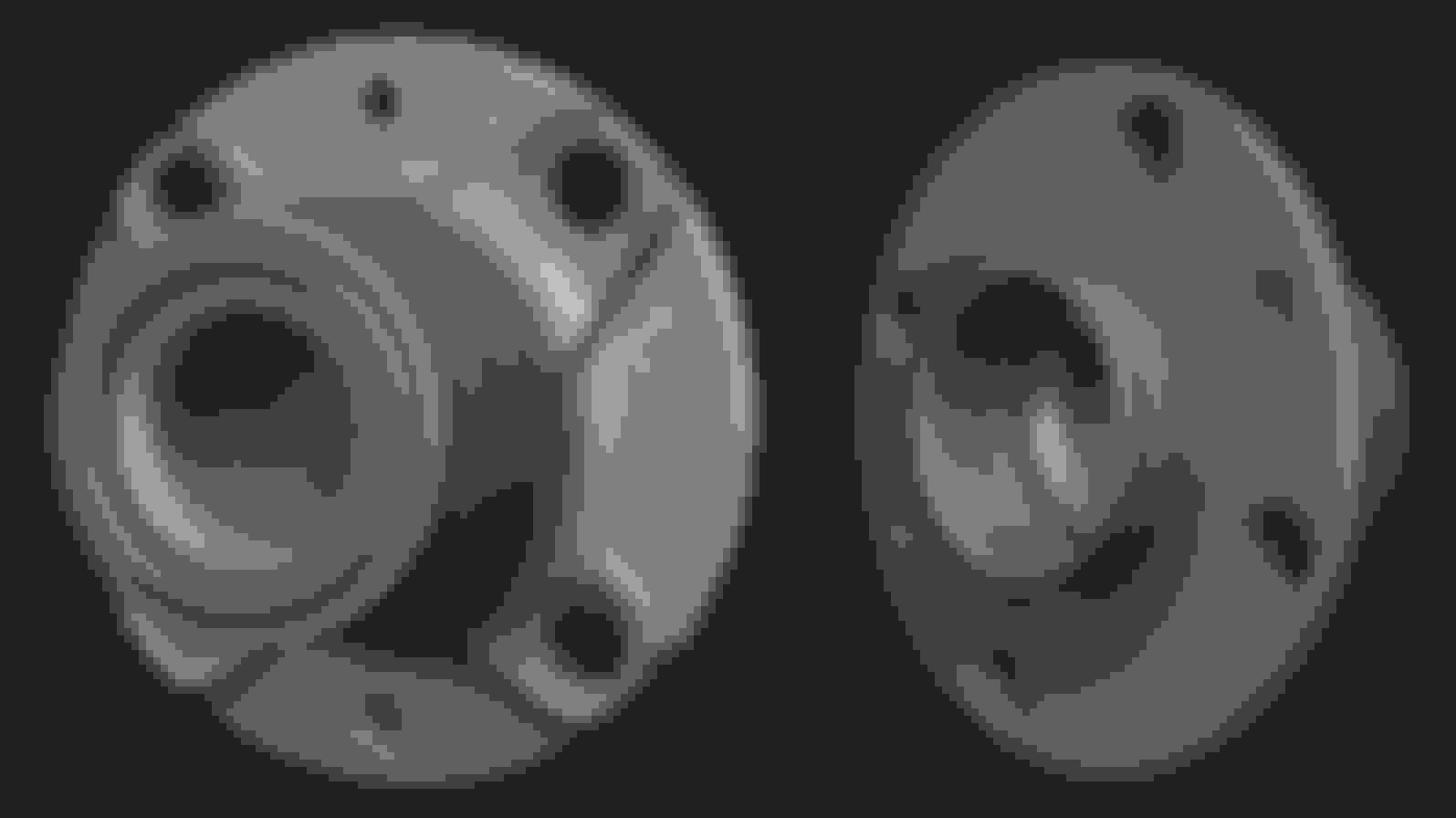
Some of the newer scans. These are a mix of scan data an manual modelling. The hyper clean/machined surfaces and things like the axle nut and wheel stud are remodeled:
A thats to much work, i have a lot of MX-5 parts in 3D but all made by myself in 3D with 3Dsmax. A lower control arm would only take me about 2 hours, but yes it would not be accurate.
But it doesnt matter for me because i only use it for 3D animation movies as seen on the IL Motorsport youtube channel
EDIT: But it does look very cool even without textures on it
Most of the work is not the scan- that 3.5 days number is for the final in game asset. The scans themselves take about 30 minutes to shoot and then process for 4-8 hours depending on how many photos.
 12-18-2016, 03:53 PM


 2
2