When you click on links to various merchants on this site and make a purchase, this can result in this site earning a commission. Affiliate programs and affiliations include, but are not limited to, the eBay Partner Network.
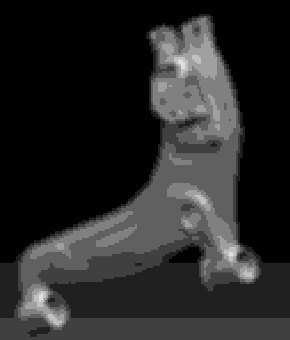
I have been slowly building a library of 3d scans of miata parts for my own projects unrelated to any real car fab. However, it occurred to me that having a library of high quality and accurate 3d scans is something that all miata fabricators could find useful. So far I have been working on this slowly, and on my own schedule. Is there significant enough interest for people to back a patreon for parts scans?
Here is an example:
The ultimate goal would be having a fairly complete library of parts freely available for download. Imagine you want to design a part, you could iterate on the design and check fit without having to actually build anything. I think this would be hugely useful for engine swaps, designing aero parts, exhaust routing, turbo manifolds...
I have. I scanned my hacked up shifter hole and some random interior bits with it. But it's manual point cloud data, so like maybe 100 points, whatever I click. We've been eyeing a laser scanner for years but have yet to be impressed with the software used to get 3D files from the scans. Seems simple, should be simple and common, but year after year, multiple sales guys, demo guys, phone conferences, live demos...we've yet to get a solidworks file of something simple that same day let alone in 30-60 minutes which is how long it takes us to do something complicated (i.e. cylinder heads) manually.
Actually this year we also looked at a lesser expensive product that use visible light cameras instead of a laser and it produced better results, quicker.
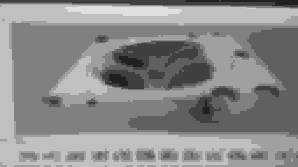
The first image I posted was 3.1 million triangles. Probably overkill for people to mock up fit off of. Here here is the same model chopped down to 14 thousand triangles which is much more manageable for most people's computers.
...we've yet to get a solidworks file of something simple that same day let alone in 30-60 minutes which is how long it takes us to do it manually.
Actually this year we also looked at a lesser expensive product that use visible light cameras instead of a laser and it produced better results, quicker.
Anyway...TL;DR this looks pretty sweet.
Careful; if you get a system that works well it reduces your job security. ;-)
I recently discovered Onshape, it's a free CAD website. It seems pretty slick to me, although I'm an utter noob when it comes to CAD. I'm sure real Solidworks users would find quite a few little features it doesn't have, but it's free and there are quite a few tutorial and videos to show how it works.
The problem I've been left with is how to find good models of parts to design against, so having a library of good accurate 3d models would be awesome.
I remember reading a paper about a research conducted by a few MIT students (grad?) that uses a cheap 3d scanner like the Kinect and dslr with a polarized filter to create really detailed scans.
I'm attaching a sample for people to take a look at. The trickiest part is establishing accurate scale. I think adding a large machinist ruler to the scans is going to be the most reliable method.
What kind of accuracy is this system capable of? I think an accurate scan of the trans bellhousing would go a long way towards making adapter plates to use a stronger trans.
Accuracy is hard to pin down to a specific number for two reasons
*accuracy of the surface varies depending on how clean and well resolved an area of the scan is.
*Scale and accuracy aren't quite the same thing, A scan can be super clean and accurate but be scaled wrong. For something as large as a subframe, a .5% scale error results in bolt holes being mis placed by several mm.
I ordered a 600mm machinist ruler that I'm going to include in my next scan. That should give me really good data to pull scale off of. I'm going to focus on making sure areas that have bolt holes are especially well resolved. Overall, I think I can get placement of bolt holes on parts accurate to about a half mm on large objects.
Any 3D scans are usefull to the community. We really need a central repository to dump them.
I use Agi photoscan for lots of parts and find its accurate enough for most development work. The key to using photos is to make sure objects have no specular highlights or reflections. Any reflections and you'll get points at the wrong depth. The photos also need to have as little noise as possible and be in focus.
I actually find using a mobile phone works fine in most cases with the scans are accurate to less than 1mm error once scaled. Plus its fast and easy.
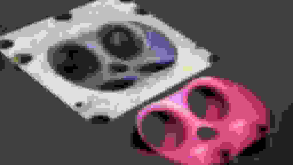
Here is a scan of an old 1.6 dohc lotus head that got mashed up when it dropped a valve. I photographed a clean chamber and built a 3D model from it. This will be used to CNC the welded up damaged chamber.
The entire process took less than a few hours including reskinning the 3D model.
Last edited by Madjak; 12-16-2016 at 12:42 AM.
Reason: mobile guff
With photoscanning it's easy to get a bend or a warp in the 3D scan if you take a series of photos along the length. Ideally it's best to take photos that cover the entire object rather than lots of overlapping photos. You at least need some photos that cover the entire object that act as a baseline for the closer photos.
I've also used a white chalking spray to cover shiny objects in a matt finish, then splatter paint or use a marker pen to create identifiable marks over the object.
For scaling, a metal ruler isn't the best as it's too reflective. You are better of printing a scale on an A4 or A3 sheet that can be seen from the main photos. My idea is to make up a scale card that can be placed next to or under smaller objects. The card will have a 'L' shaped scale for easy alignment as well as a couple of other glyphs to double check the square. If I make one and test it I'll post it up, but the main thing is that the scale card needs to be inflexible and large enough to be accurate.
Interesting, I recently had a BP4W head shipped to my uni's workshop and have pretty much unlimited time with the Faro arm. And flowbench for that matter
For scaling, a metal ruler isn't the best as it's too reflective. You are better of printing a scale on an A4 or A3 sheet that can be seen from the main photos. My idea is to make up a scale card that can be placed next to or under smaller objects. The card will have a 'L' shaped scale for easy alignment as well as a couple of other glyphs to double check the square. If I make one and test it I'll post it up, but the main thing is that the scale card needs to be inflexible and large enough to be accurate.
He bought a scale with a matte finish made specifically for this use, pretty cheap on amazon.
I remember reading a paper about a research conducted by a few MIT students (grad?) that uses a cheap 3d scanner like the Kinect and dslr with a polarized filter to create really detailed scans.
I would love a library of 3d scanned parts!
I remember trying the Kinect thing in college, but if memory serves me correct, the dimensions were so inaccurate that they could not be used. We ended up using a local company's Faro arm instead.
He bought a scale with a matte finish made specifically for this use, pretty cheap on amazon.
Yeah, it has a satin finish which isn't quite ideal. I ran a strip of painters tape down it so the scan could have something easy to grab onto. The tick marks are placed right up to the edge of the painters tape so I can make accurate distances.
 12-15-2016, 11:01 AM


 6
6