Another TPS Option for 90-93MT: TPS4185
 10-06-2013, 11:33 PM
#1
Elite Member
Thread Starter
iTrader: (4)

Join Date: Mar 2008
Location: Granbury, TX
Posts: 6,301
Total Cats: 696
My trusty TPS201 died after about 30K miles of faithful service. The TPS201 saga can be found here:
https://www.miataturbo.net/megasquir...9/#post1060119
Because I wanted to get this fixed RIGHT NOW, I went to the zone to get a replacement. Low and behold . . . no TPS201s in stock . . . I'd have to wait a couple of days. Apparently, whatever car the TPS201 goes on is now too old for the zone to stock replacements. Same story at O'Reillys when they cross-referenced the TPS201.
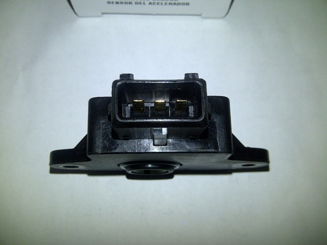
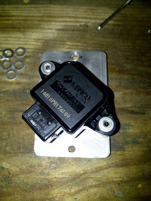
Since I still wanted to get it fixed RIGHT NOW, I took the opportunity to see if there was another TPS that was stocked and might work. It turns out there is. Meet the TPS4185 (as used on mid-2000s Kias -- many of which used Mazda B6s and BPs):
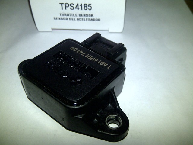
It actually has the right connector!
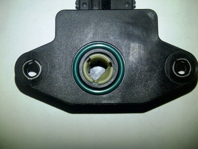
And the right shaft fitting!
Costwise, it's ~$13 more than the current list for the TPS201 ($53 vs. $40 -- at Rock Auto the TPS4185 is $33+shipping). But the good thing is that it can be used without modification so that the lifetime warranty stays intact. I felt that was worth $13.
To use this TPS, there are two minor issues that need to be addressed:
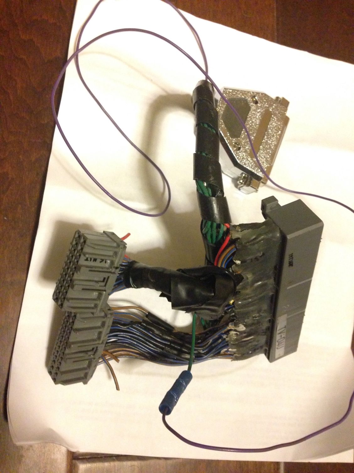
1. The power and ground pins are reversed relative to the stock 90-93 MT wiring harness. Some minor harness surgery is required. The wires that have to be reversed are the Red (+5VDC, goes to pin 1N on the ECU connector) and Black/Light Green (ECU ground, goes to engine block and pin 2C on the ECU connector). I did the surgery in the harness about 3 inches from the TPS connector.
2. Although the TPS fits the shaft end, the Miata's throttle body shaft is too long. So, you either need to add some spacers or drill a hole in the TPS case for the shaft to pass through. I opted to add spacers. This leaves the TPS completely intact so I can take advantage of the lifetime warranty.
Here's some pictures of how I mounted the TPS:
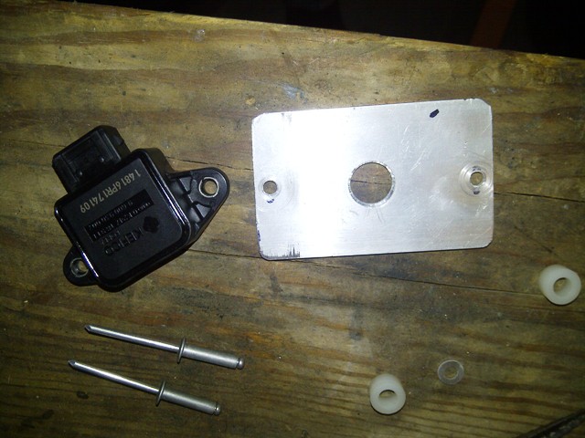
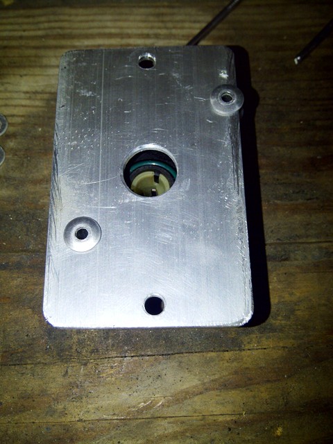
The TPS mounting holes are neither far enough apart nor at the correct angle to bolt directly to the throttle body. This plus the spacing problem means that I needed to fabricate an adapter plate. I made one out of 1/8" aluminum stock using my old TPS as a template:
Here are the parts for the assembly. I trial-fitted the adapter plate and TPS to the car to get the correct angle (you can see my mark on the adapter plate). The adapter plate holes are 3/8" for the mounting screws and 9/16" for the TPS shaft. The TPS shaft hole is exactly centered between the mounting holes. I placed the TPS into the 9/16" hole and lined it up with the mark to create TPS mounting holes. These were 3/8" as well and fit the long aluminum rivets in the picture.
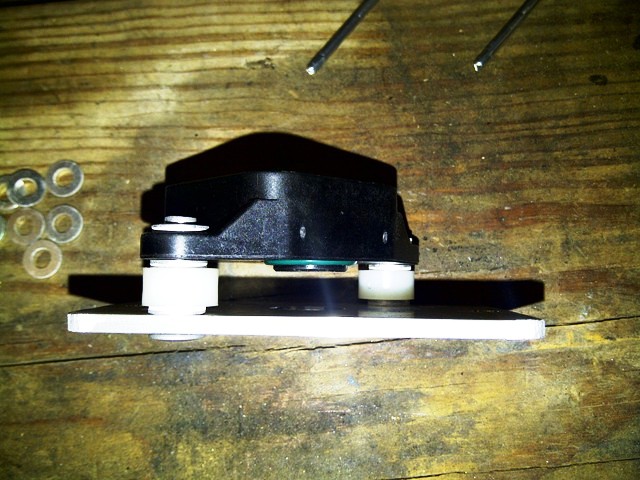
Finished assembly:
I used a nylon spacer along with two 3/8" aluminum rivet backing washers to space the TPS.
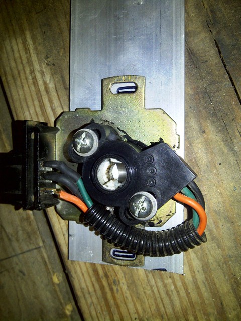
Mounted on the car:
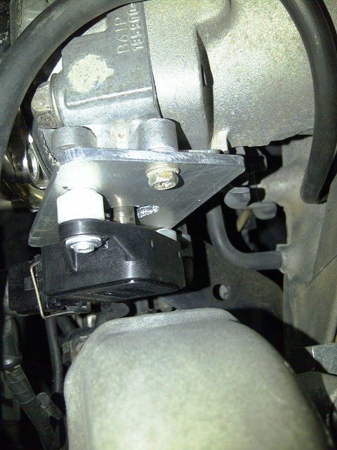
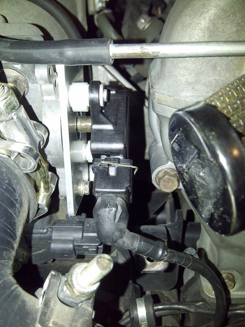
It works perfectly.
https://www.miataturbo.net/megasquir...9/#post1060119
Because I wanted to get this fixed RIGHT NOW, I went to the zone to get a replacement. Low and behold . . . no TPS201s in stock . . . I'd have to wait a couple of days. Apparently, whatever car the TPS201 goes on is now too old for the zone to stock replacements. Same story at O'Reillys when they cross-referenced the TPS201.
Since I still wanted to get it fixed RIGHT NOW, I took the opportunity to see if there was another TPS that was stocked and might work. It turns out there is. Meet the TPS4185 (as used on mid-2000s Kias -- many of which used Mazda B6s and BPs):
It actually has the right connector!
And the right shaft fitting!
Costwise, it's ~$13 more than the current list for the TPS201 ($53 vs. $40 -- at Rock Auto the TPS4185 is $33+shipping). But the good thing is that it can be used without modification so that the lifetime warranty stays intact. I felt that was worth $13.
To use this TPS, there are two minor issues that need to be addressed:
1. The power and ground pins are reversed relative to the stock 90-93 MT wiring harness. Some minor harness surgery is required. The wires that have to be reversed are the Red (+5VDC, goes to pin 1N on the ECU connector) and Black/Light Green (ECU ground, goes to engine block and pin 2C on the ECU connector). I did the surgery in the harness about 3 inches from the TPS connector.
2. Although the TPS fits the shaft end, the Miata's throttle body shaft is too long. So, you either need to add some spacers or drill a hole in the TPS case for the shaft to pass through. I opted to add spacers. This leaves the TPS completely intact so I can take advantage of the lifetime warranty.
Here's some pictures of how I mounted the TPS:
The TPS mounting holes are neither far enough apart nor at the correct angle to bolt directly to the throttle body. This plus the spacing problem means that I needed to fabricate an adapter plate. I made one out of 1/8" aluminum stock using my old TPS as a template:
Here are the parts for the assembly. I trial-fitted the adapter plate and TPS to the car to get the correct angle (you can see my mark on the adapter plate). The adapter plate holes are 3/8" for the mounting screws and 9/16" for the TPS shaft. The TPS shaft hole is exactly centered between the mounting holes. I placed the TPS into the 9/16" hole and lined it up with the mark to create TPS mounting holes. These were 3/8" as well and fit the long aluminum rivets in the picture.
Finished assembly:
I used a nylon spacer along with two 3/8" aluminum rivet backing washers to space the TPS.
Mounted on the car:
It works perfectly.
Last edited by hornetball; 10-08-2013 at 06:11 PM.

Reply
 3
3

3
 .
10-10-2013, 11:38 AM
.
10-10-2013, 11:38 AM
#5
Elite Member
Thread Starter
iTrader: (4)
Join Date: Mar 2008
Location: Granbury, TX
Posts: 6,301
Total Cats: 696
BTW, you might also be able to compensate for the reverse action with calibration. With my MSPNP, I was able to accomplish this with a custom throttlefactor.ini file. The problem was that MS1 uses different types of TPS measurements for different parts of the code (some parts used %TP which I could correct, some parts used ADC which I couldn't correct). So with MS1 I had no choice but to swap the wires.
What about MS3? Maybe you can just compensate for the reverse action with calibration and be OK?
What about MS3? Maybe you can just compensate for the reverse action with calibration and be OK?
Reply
0
0
 10-10-2013, 04:44 PM
#9
Elite Member
Thread Starter
iTrader: (4)
Join Date: Mar 2008
Location: Granbury, TX
Posts: 6,301
Total Cats: 696
Problem is that the MS algorithms don't always use the final result ("TPScalibrated" in your example). Oftentimes, they are using the raw ADC value.
Not great code architecture.
Reply
0
0
08-24-2015, 02:16 AM
#10
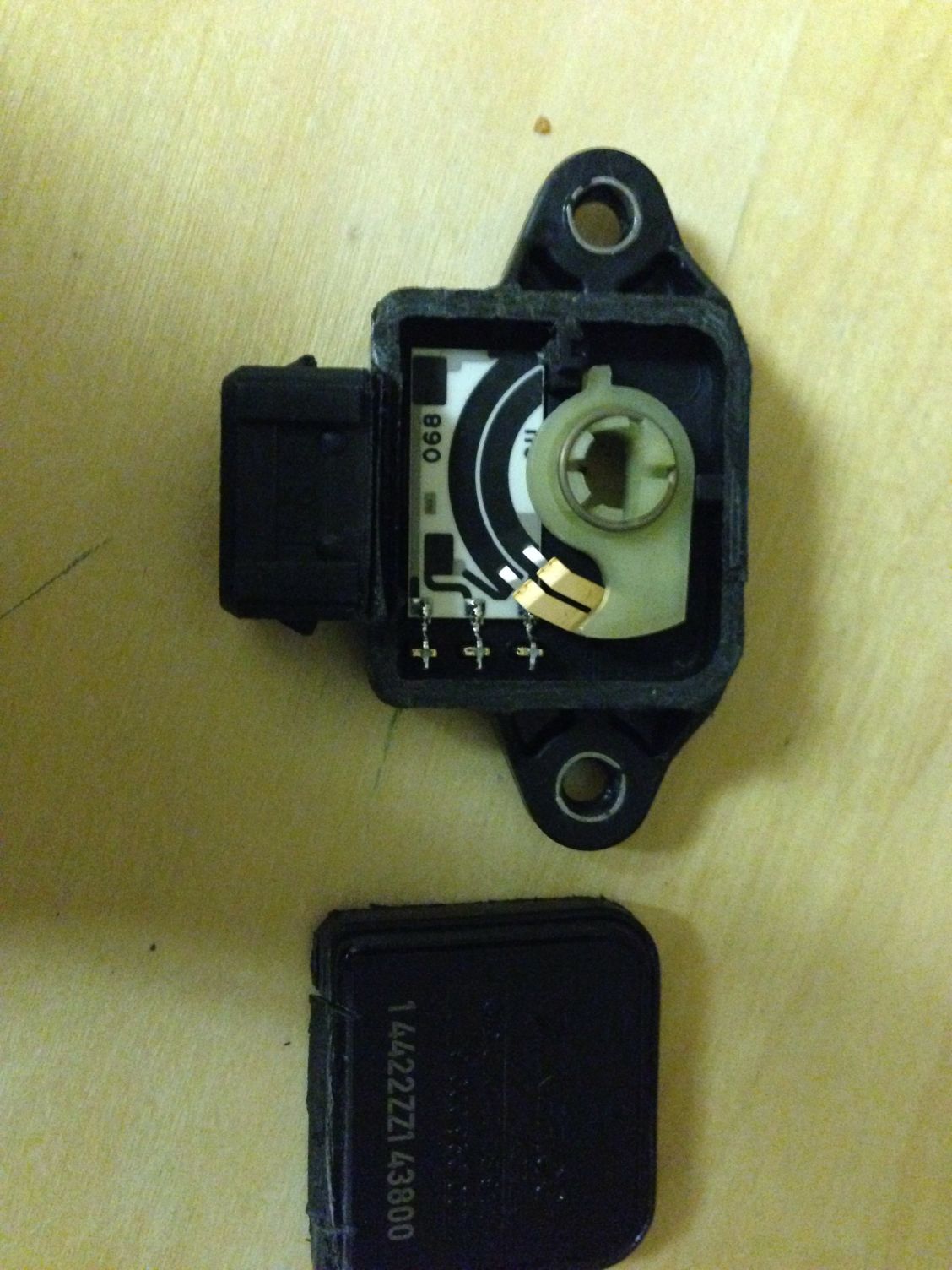
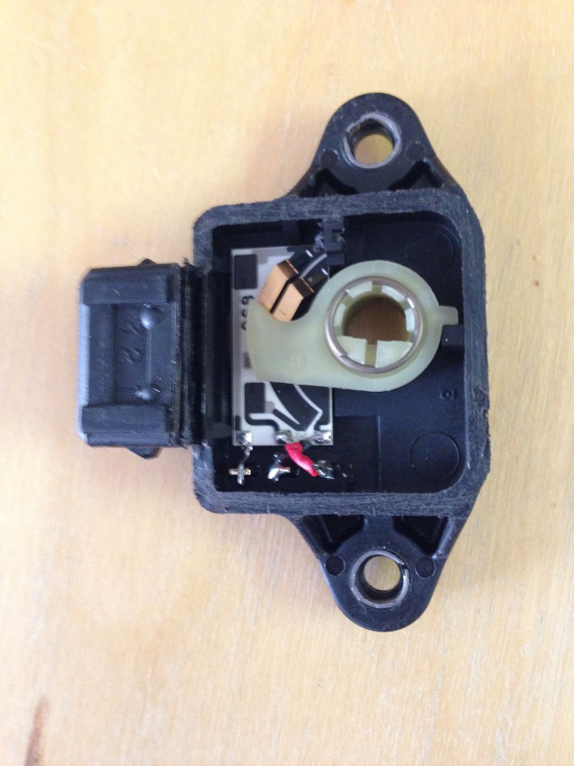
I decided to take on Brainack's challenge and get on of these TPSs and crack it open and re wire it.<br/><br/>First, opening it was a pain because it is fully sealed and I'm honestly not sure how they assembled it as it has no parting lines. I carefully sawed it apart hoping not to hit something inside.<br/><br/>Once open I can tell this is going to be trickier than just unsoldering wire and re soldering in a new configuration.<br/>
Reply
0
0
08-24-2015, 02:32 AM
#11
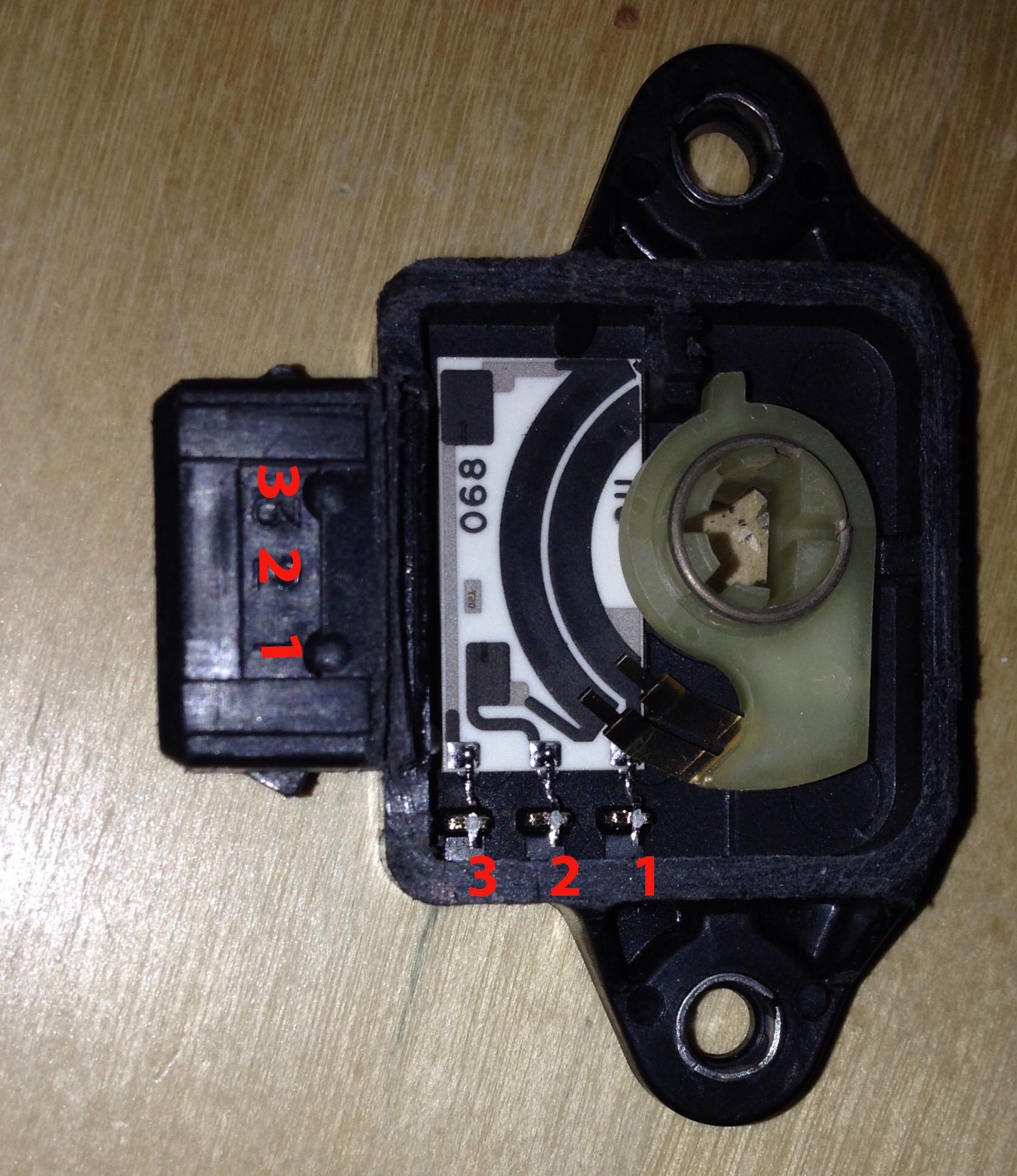
Ok so I've got the thing open and here is what I have found using my multimeter:
On the connector side the pins are labeled as 3,2,1 going from top to bottom and they correspond in the box as 3,2,1 going from left to right.
When I test the connectors I get the following readings:
3&1 - wide open 2.75ohms to closed .89ohms
3&2 - wide open.89ohms to 2.75ohms closed
2&1 - same 2.08ohms continues no mater the throttle position
So, how should I rewire it for my manual 91 assuming I can get wires into that tight space without interfering with the movement of the contacts as they sweep across the PCB?
Reply
0
0
08-24-2015, 09:20 AM
#12
Boost Czar


iTrader: (62)
Join Date: May 2005
Location: Chantilly, VA
Posts: 79,494
Total Cats: 4,080
too early to think, but looks ez.
looks like like pin 1 is ground and you just need to swap 2 and 3.
im assuming the leads on the bottom of the case in that pic go directly to the harness connector? if so then that looks like a really ezpz quick fix.
looks like like pin 1 is ground and you just need to swap 2 and 3.
im assuming the leads on the bottom of the case in that pic go directly to the harness connector? if so then that looks like a really ezpz quick fix.
Reply
0
0
 08-24-2015, 01:13 PM
#15
Boost Czar
iTrader: (62)
Join Date: May 2005
Location: Chantilly, VA
Posts: 79,494
Total Cats: 4,080
The resistance between the VREF and ground pins will remain constant.
The resistance between the ground and signal pins will be low with the throttle closed and high with the throttle wide open.
The resistance between the VREF and signal pins will be high with the throttle closed and low with the throttle wide open.
The resistance between the ground and signal pins will be low with the throttle closed and high with the throttle wide open.
The resistance between the VREF and signal pins will be high with the throttle closed and low with the throttle wide open.
3&1 - wide open 2.75ohms to closed .89ohms
3&2 - wide open.89ohms to 2.75ohms closed
2&1 - same 2.08ohms continues no matter the throttle position
3&2 - wide open.89ohms to 2.75ohms closed
2&1 - same 2.08ohms continues no matter the throttle position
pretty sure this:
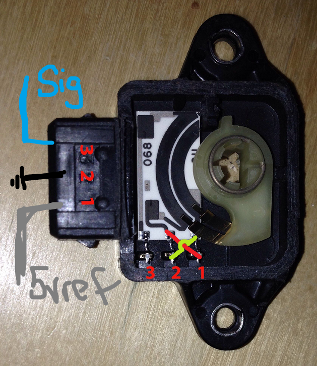
flipping the 5vref and ground.
Last edited by Braineack; 08-24-2015 at 01:31 PM.
Reply
0
0
08-28-2015, 02:45 AM
#16
More progress on the not really Plug-n-Play VTPS.
Rewired
Rewired ground and Vref
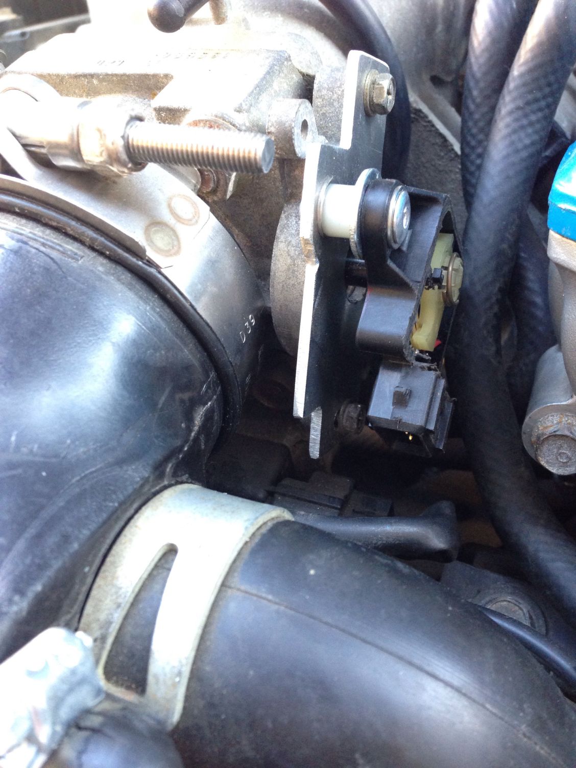
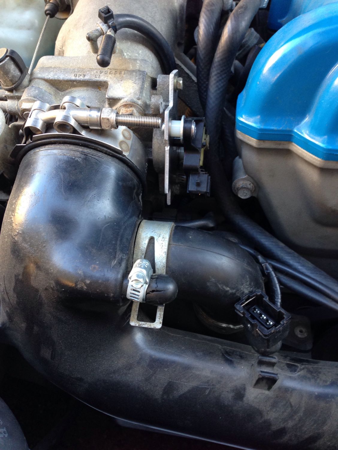
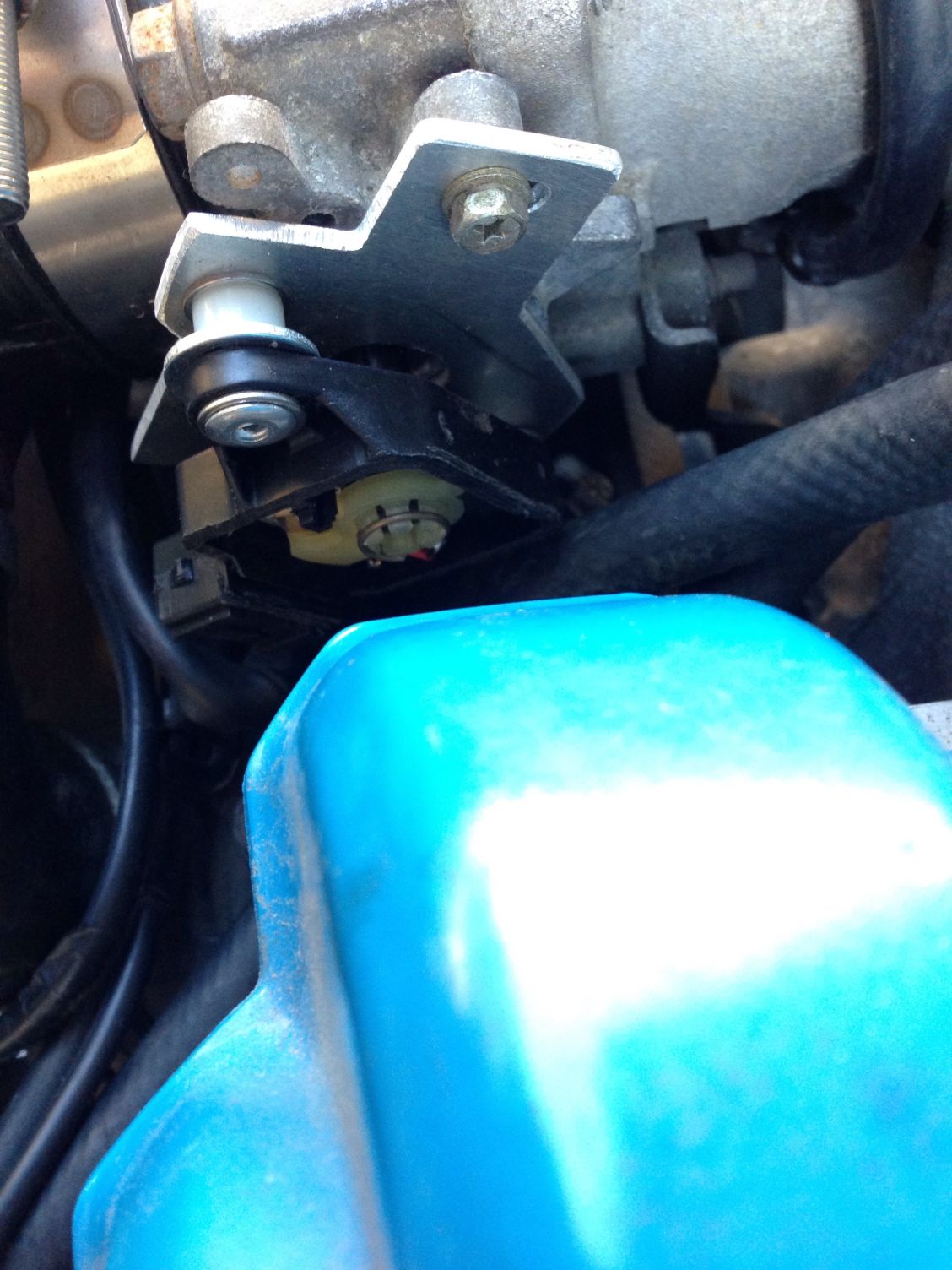
After what seemed like quite a bit of fabricating I finally got the whole thing together. Seems to work well but it is an absolute bitch to thread in the lower bolt now. After seeing that everything
turns soothly I took it off so I can glue the top I cut off back on. I really wish that it mounted in the same direction as the original but the key to the throttle shaft does not allow for it. At least this means I can get it off and back to stock relatively easily every two years for smog.
Rewired
Rewired ground and Vref
After what seemed like quite a bit of fabricating I finally got the whole thing together. Seems to work well but it is an absolute bitch to thread in the lower bolt now. After seeing that everything
turns soothly I took it off so I can glue the top I cut off back on. I really wish that it mounted in the same direction as the original but the key to the throttle shaft does not allow for it. At least this means I can get it off and back to stock relatively easily every two years for smog.
Reply
0
0
08-28-2015, 06:09 PM
#19
More progress on the not really Plug-n-Play VTPS.
Rewired
Rewired ground and Vref
After what seemed like quite a bit of fabricating I finally got the whole thing together. Seems to work well but it is an absolute bitch to thread in the lower bolt now. After seeing that everything
turns soothly I took it off so I can glue the top I cut off back on. I really wish that it mounted in the same direction as the original but the key to the throttle shaft does not allow for it. At least this means I can get it off and back to stock relatively easily every two years for smog.
I will switch the pins and report back.

Reply
0
0