DIYPNP with BMW variable tps needle response
 06-14-2013, 06:40 PM
#1
Junior Member
Thread Starter

Join Date: Jul 2007
Location: Chitown Illinois
Posts: 55
Total Cats: 0
Hello,
I just started the car for the first time (90 1.6L). Using home built DIYPNP with v1.5 board. I installed the bmw tps, calibrated per instructions. Tunerstudios sees the tps, 0 and 100% throttle works well, but the response for in between values is slow. For example if i press the throttle down to ~20% the gauge in tunerstudios slowly works its way up, only i when i go WOT or no throttle does it rapidly go to those values. Is this normal or do i have bad sensor? I have double checked the wiring mod to run variable tps, seems ok.
I can post a video of the screen if this is unclear.
Thanks in advance.

Reply
 0
0

0
06-15-2013, 01:23 PM
#2
Junior Member

Join Date: Sep 2011
Location: finger lakes NY
Posts: 433
Total Cats: 17
Does the TS gauge eventually get to the correct value, even if it does take a long time? You would get exactly that behavior if there were WAY too much filter capacitance. Conceivably, it could also happen if the TPS resistance from end to end were ridiculously high, but others have used BMW TPS's....
The Microsquirt module has only a fraction of a uF of filter capacitance. If there were additional caps on the DIYPNP board for the TPS circuit, then I'd accuse you of installing the wrong ones, but I don't think there are any.
What mod would that be?
The Microsquirt module has only a fraction of a uF of filter capacitance. If there were additional caps on the DIYPNP board for the TPS circuit, then I'd accuse you of installing the wrong ones, but I don't think there are any.
I have double checked the wiring mod to run variable tps, seems ok.
Reply
0
0
06-15-2013, 02:12 PM
#3
Junior Member
Thread Starter
Join Date: Jul 2007
Location: Chitown Illinois
Posts: 55
Total Cats: 0
the needle moves so slow its hard to keep the pressure on the pedal steady to see if it gets to the right value.
When i test it on the bench (w/ no sensor plugged in), the tps goes to 87% by it self.
There was one capacitor I wasn't 100% sure on, in the pull ups IAC - FB Diode to 12V
When i say mod i mean jumping SIG to 4L & VREF to 1N variable tps
per
DIYPNP MegaSquirt installation for the Mazda Miata
Here is a picture of the board maybe you can see something wrong:
Reply
0
0
06-15-2013, 06:10 PM
#4
Junior Member
Join Date: Sep 2011
Location: finger lakes NY
Posts: 433
Total Cats: 17
Stuff looks right in the photos... as far as I can tell.
It would take a LOT of capacitance to slow things down that much. The other possibility is a lot of resistance.
Measure the resistance between the two ends (should be constant at all throttle positions.) And also between the wiper and the two ends while moving the throttle. Ideally, this would be done at the ECU end of the harness. Unplug the ECU and measure (at the harness) between 1N and 4C (Vref and GND) and between 4L and 4C as you work the pedal.
Reply
0
0
06-15-2013, 10:40 PM
#5
Junior Member
Thread Starter
Join Date: Jul 2007
Location: Chitown Illinois
Posts: 55
Total Cats: 0
At the harness:
1N to 4C - open at all throttle positions
4L to 4C- ~10.9 ohm at 0 throttle, open for any throttle percentage above 0.
I measured the ecu on the bench (unplugged)
1N to 4C -752 ohm
4L to 4C - 1845 ohm
1N to 4C - open at all throttle positions
4L to 4C- ~10.9 ohm at 0 throttle, open for any throttle percentage above 0.
I measured the ecu on the bench (unplugged)
1N to 4C -752 ohm
4L to 4C - 1845 ohm
Reply
0
0
06-16-2013, 05:53 AM
#6
Senior Member

Join Date: Nov 2007
Location: Belgium
Posts: 999
Total Cats: 73
My guess is that you have your wiring wrong. You probably swapped Vsignal and Gnd. I did the same thing on mine and had the same symptoms. 0% and 100% were ok, but pressing the throttle did nearly nothing until near WOT.
Measure Vsignal on the tps while turning the throttle. Should go from 0V to 5V.
Measure Vsignal on the tps while turning the throttle. Should go from 0V to 5V.
Reply
0
0
06-16-2013, 12:06 PM
#7
Junior Member
Thread Starter
Join Date: Jul 2007
Location: Chitown Illinois
Posts: 55
Total Cats: 0
My guess is that you have your wiring wrong. You probably swapped Vsignal and Gnd. I did the same thing on mine and had the same symptoms. 0% and 100% were ok, but pressing the throttle did nearly nothing until near WOT.
Measure Vsignal on the tps while turning the throttle. Should go from 0V to 5V.
Measure Vsignal on the tps while turning the throttle. Should go from 0V to 5V.
Reply
0
0
06-16-2013, 12:08 PM
#8
Junior Member
Join Date: Sep 2011
Location: finger lakes NY
Posts: 433
Total Cats: 17
That indicates either a mistake in your wiring or a failed TPS (or a measurement error.)
The TPS is just a potentiometer. When you measure between 1N and 4C you're measuring from end to end and should get something like a few hundred ohms to a couple thousand ohms; I'm not familiar with the BMW part.
My next step would be to measure the TPS itself. If it looked OK then I'd start looking for a wiring mixup. I don't know what source of info you used, but this seems like a complete write up:
My Turbo Miata Photo Journal - Variable TPS
The 10th picture shows how to connect to the potentiometer.
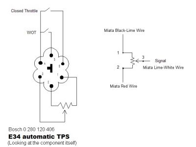
Reply
0
0
06-16-2013, 12:36 PM
#9
Junior Member
Thread Starter
Join Date: Jul 2007
Location: Chitown Illinois
Posts: 55
Total Cats: 0
If i understand correctly 1 to 2 should have some steady resistance, measuring at the sensor between 1 & 2 I have an open at all throttle positions. Between 2 & 3 is also open, it briefly flashes ~1800ohms when nearing WOT.
Reply
0
0
06-16-2013, 12:47 PM
#10
Supporting Vendor


iTrader: (33)
Join Date: Jul 2006
Location: atlanta-ish
Posts: 12,659
Total Cats: 134
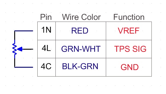
Pull the plug off the TPS and measure like this:
The easiest way to check a TPS is to unplug it and put an ohmmeter on its pins. Observe the resistance as the throttle opens and closes. Each pair of pins will behave differently:
The resistance between the VREF and ground pins will remain constant.
The resistance between the ground and signal pins will be low with the throttle closed and high with the throttle wide open.
The resistance between the VREF and signal pins will be high with the throttle closed and low with the throttle wide open.
If it does not behave like this, you have a faulty TPS. If it does, plug the TPS back in and do the same test, but measure each pin at the DIYPNP's adapter board.
If it passes, measure at the DIYPNP main board.
If it passes, measure at the Microsquirt module itself.
My bet is faulty TPS.

Reply
0
0
06-16-2013, 01:01 PM
#11
Junior Member
Thread Starter
Join Date: Jul 2007
Location: Chitown Illinois
Posts: 55
Total Cats: 0
Ah i figured it out, the conversion harness for tps was made incorrectly, i was getting pins 4,5,6 , which is closed and wot. rewired 1,2,3 & calibrated, now works as it should.
Thanks guys!
Thanks guys!
Reply
0
0


Thread
Thread Starter
Forum
Replies
Last Post
Zaphod
MEGAsquirt
47
10-26-2018 11:00 PM


