Help me pass emissions
 01-24-2016, 07:24 PM
#41
Junior Member
Thread Starter

Join Date: Mar 2010
Location: Melissa, TX
Posts: 172
Total Cats: 20
have you actually looked at the signal voltage yet? both before the MS input circuit, and then just before the CPU, using either ground as a reference?
Have you determined that the LC2 isnt itself outputting junk on the yellow analog one output? or that the MS itself is doing something to the signal after it's own input circuit?
i was finally able to log at your log, it looks like a lot going "oddly". This was during the emissions run?
what's your setup like? can you post your actual msq?
I'll post the MSQ when I get home. I am sure there are a thousand things wrong with it, I just got started messing with it from the base tune Reverant gave me I've only made some changes to the knock threshold, adjusted the idle control loop and the EGO loop.
Its a 2004 VVT motor in a '93 chassis with the 5speed and the 4.3 viscous diff. Intake is an AEM thing from 949. Exhaust is a racing beat header with a magnaflow direct fit cat and a junkyard special kind of catback. Injectors are the OEM 2004s, as are the ignition coils. I put new NGK Sparkplugs in gapped at .044 thinking that the bounce in AFR was crap combustion (before I checked the serial output of the LC-2). Intake manifold is the 2004 VTCS, with the VTCS system removed and sealed (though not between the runners). No EGR system hooked up. I posted wiring diagrams in the build thread here: https://www.miataturbo.net/meet-gree...9/#post1224622 On the DB37 connector I have the knock, VVT and wideband +12v, Ground & signal wired up (5 total connections)
I've not scoped anything inside the MS3, what things I have checked are in measured relative the digital ground of the ECU, when you measure the signal relative to the chassis ground you get a pretty clean output. MY initial assumption was that I had a bad connection so I checked the ground, signal and 12v on the LC2 CCA and on the DB37 and found them to be nearly identical, Both in voltage and in the noise. The MS3 logs look exactly like the noise, except the frequency is off because the noise has a higher frequency than the MS3 is sampling at.

Reply
 0
0

0
01-24-2016, 07:35 PM
#42
Junior Member
Thread Starter
Join Date: Mar 2010
Location: Melissa, TX
Posts: 172
Total Cats: 20
I think you have started down the right path of looking for ground currents. I would consider the possibility that the WB heater current is the culprit. As drawn up there ^ all of your heater current is flowing through the reference plane of the MS. A few suggestions:
- Decouple the sensor return to the chassis with a low ESR capacitor
- Add a common mode wrap on the lines running to the WB
- Decouple both the 12V and the signal out of the WB to their local return with capacitors
- Provide a local (to the WB) low impedance DC path from the sensor directly to the chassis return. Run a second low current return reference back to the aquisition system. You could force the heater currents through the low Z path with a common mode choke on the power lines and then another on the signal/reference lines (assumes high z input on the DAQ)
When it comes to fixing this electrically I think I will either separate the heater and signal grounds on the LC2 (studying the PWB it looks like this should be easy, but I want confirmation from innovate) or I will add a zero gain differential op amp referencing the 0-5V output of the LC2 to the chassis ground and feed its output into the MS3. Based on what I've seen with my scope this should result in a clean signal into the MS3 and its how we deal with common mode noise at work, where we deal with dirty aircraft power and grounds, and need EMI hardening.
Reply
0
0
01-24-2016, 07:45 PM
#43
Tweaking Enginerd

iTrader: (2)

Join Date: Mar 2013
Location: Boulder, CO
Posts: 1,773
Total Cats: 355
I assume you mean a gain of 1 
The diff amp is effective for impedance transformations to be sure. If you believe the noise source is due to victim coupling then it certainly could improve things for you.
Based on your results described above (from my couch that is) it sounds to me like you have enough ground current to react with the impedance between the sensor return and chassis. If you can separate the high current return from signal and route it directly to the chassis, I say thumbs up brother!
Reply
0
0
01-24-2016, 08:46 PM
#45
Junior Member
Thread Starter
Join Date: Mar 2010
Location: Melissa, TX
Posts: 172
Total Cats: 20
Terminology is fun. Looking up parts its also called a "Unity Gain Differential Amplifier."
Attached is the .msq for the curious. Pretty confident the problem isn't in here but who knows.
Attached is the .msq for the curious. Pretty confident the problem isn't in here but who knows.
Reply
0
0
01-26-2016, 11:14 AM
#48
Junior Member
Thread Starter
Join Date: Mar 2010
Location: Melissa, TX
Posts: 172
Total Cats: 20
All this buisness about adding something to filter the noise, why can't I just modify the RC circuit on the MS3 to kill it? The noise is right around 500hz. By the MS3 schematics the RC circuit for the EGO input has a cutoff frequency of ~700hz (R=1k, C=.22uF)
What if I just changed it to match the MAT input filter, with a cutoff frequency of 70hz? (R=2.2K, C=1uF) Per the calculator the transient response would go from .0015s to .015s but the LC2 only runs at 12hz so the transient only makes up 18% of the time between updates and would give me 15db or so of supression at 500hz. That would turn my .2V noise into .036v noise, combined with the improvement of grounding on the chassis would make the noise .009V, which should be acceptable. I do lose some transient response, but I should be able to tune in the EGO delay somewhere right?
What if I just changed it to match the MAT input filter, with a cutoff frequency of 70hz? (R=2.2K, C=1uF) Per the calculator the transient response would go from .0015s to .015s but the LC2 only runs at 12hz so the transient only makes up 18% of the time between updates and would give me 15db or so of supression at 500hz. That would turn my .2V noise into .036v noise, combined with the improvement of grounding on the chassis would make the noise .009V, which should be acceptable. I do lose some transient response, but I should be able to tune in the EGO delay somewhere right?
Reply
0
0
01-26-2016, 12:55 PM
#49
Boost Czar

iTrader: (62)
Join Date: May 2005
Location: Chantilly, VA
Posts: 79,493
Total Cats: 4,080
im still going with the grounds are fine and you need to look at the wb's 0-5v signal output.
but if you wanna build crazy circuits you absolutely dont need and wont fix the problem.... thats on you :P
LC1s, LC2s, MTX-Ls are all very common among members here. So are MS Labs MS3-Basics; no one else here is jump through hoops like this. The problem lies within the ECU or WBo2.
but if you wanna build crazy circuits you absolutely dont need and wont fix the problem.... thats on you :P
LC1s, LC2s, MTX-Ls are all very common among members here. So are MS Labs MS3-Basics; no one else here is jump through hoops like this. The problem lies within the ECU or WBo2.
Reply
0
0
01-26-2016, 02:25 PM
#50
Junior Member
Thread Starter
Join Date: Mar 2010
Location: Melissa, TX
Posts: 172
Total Cats: 20
im still going with the grounds are fine and you need to look at the wb's 0-5v signal output.
but if you wanna build crazy circuits you absolutely dont need and wont fix the problem.... thats on you :P
LC1s, LC2s, MTX-Ls are all very common among members here. So are MS Labs MS3-Basics; no one else here is jump through hoops like this. The problem lies within the ECU or WBo2.
but if you wanna build crazy circuits you absolutely dont need and wont fix the problem.... thats on you :P
LC1s, LC2s, MTX-Ls are all very common among members here. So are MS Labs MS3-Basics; no one else here is jump through hoops like this. The problem lies within the ECU or WBo2.
Reply
0
0
 01-26-2016, 11:34 PM
#52
Junior Member
Thread Starter
Join Date: Mar 2010
Location: Melissa, TX
Posts: 172
Total Cats: 20
I talked to innovate today, the PCB for the LC-2 has a common ground plane that the processor sits on, without any jumper resistors or similar to be able to modify it. I would have to lift a pin on the chip and then solder a jumper onto it to separate the grounds. They suggested that they have seen lots of issues when installed into NA Miata, and the the best solution is to run a wire directly back to the battery up to the ECU/LC2 to ground to.
So I got some 10 gauge wire and ran it up to the passenger compartment. I added a wire to pin 21 of the DB37 which is another chassis ground, and attached it to the 10 gauge wire. The wire off of the DB37 is much smaller 24 gauge though so its not an ideal final solution. The ground\signal bounce was much much improved, though still present. I could measure the ground bounce at the ECU, but not at the exposed end of the 10 gauge wire, so I suspect with more copper grounding the ECU I could drive the issue to ground.
With that in mind I looked at the stock connectors on the other side, plan would be to strip and wrap solder 20 gauge wire to each of the 4 ground wires, then tie all 4 leads to the 10 gauge wire to the battery. Investigating this I noticed that 3 of the 4 ground pins on the ECU are not connected to the chassis ground pins on the DB37 connector. The other 4 ground pins are connected to the analog ground. This seems incorrect, considering the power put into the chassis ground by injectors/WB heater, etc.. I would expect the chassis ground to have 3 pins, and the analog ground to have 1. Can someone else with a MSlabs MS3 basic check this out?
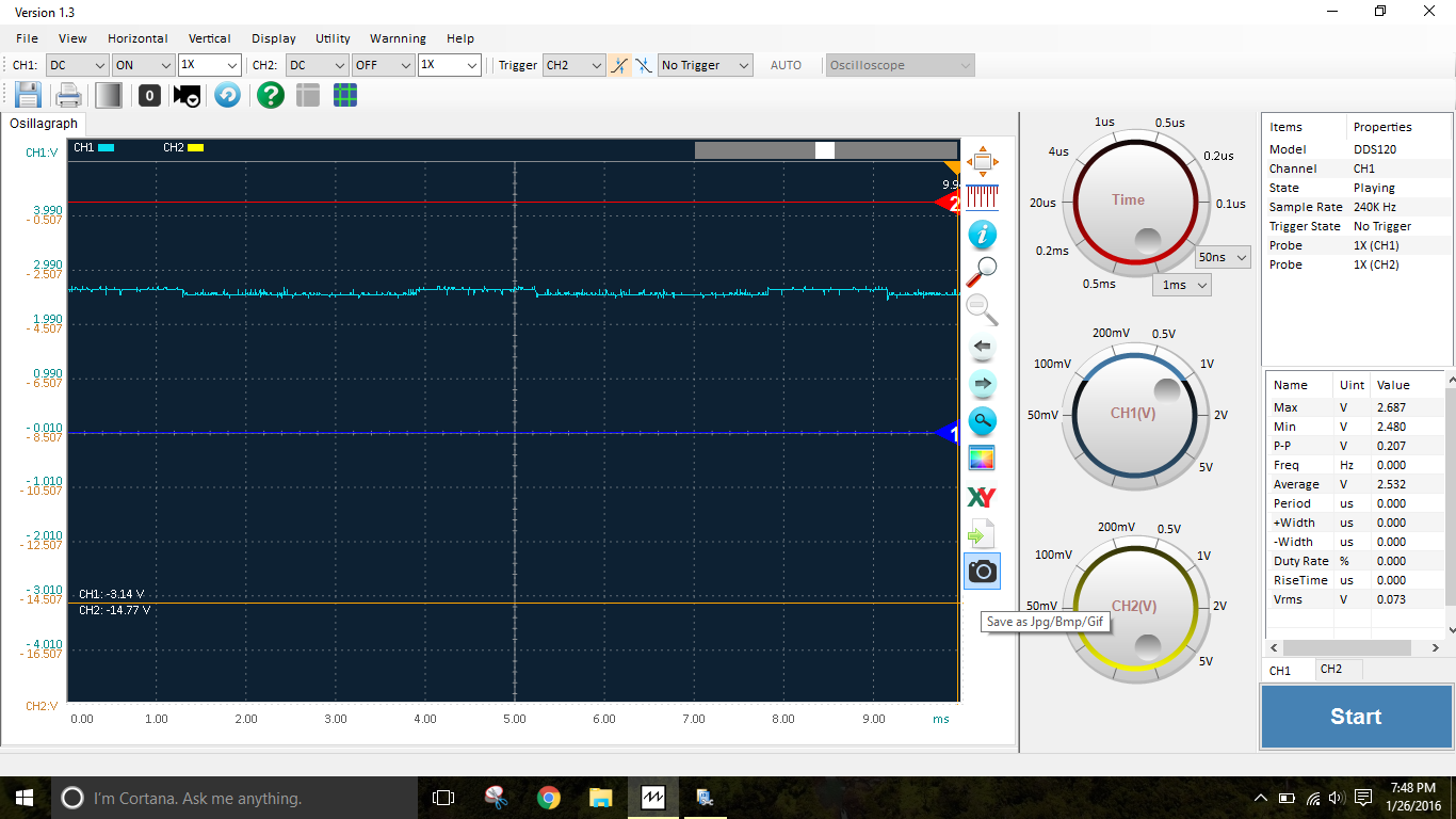
Ground Bounce with key on, engine off
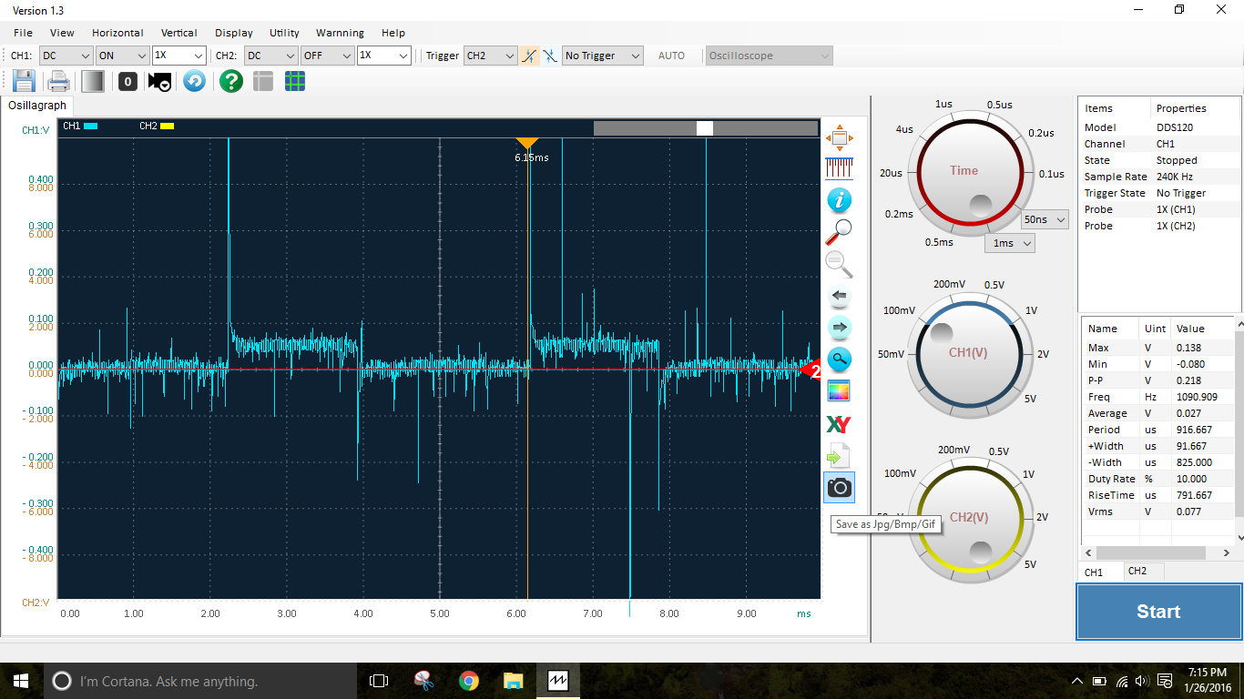
Ground Bounce with engine running

12V car running

Signal Bounce relative to pin 3 (analog ground)with ground to battery
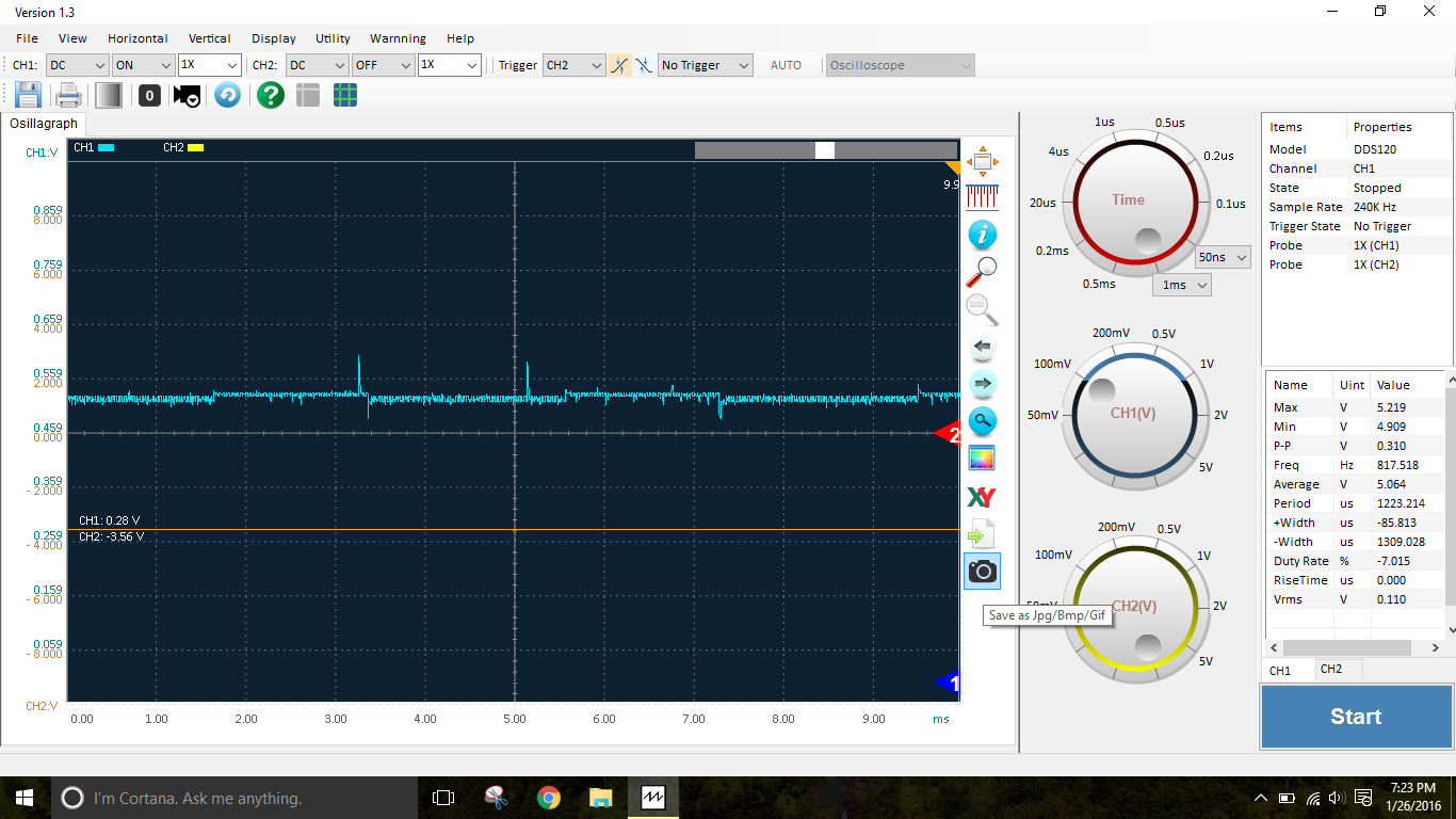
Signal Bounce relative to end of 10 gauge wire (should be noted there was no bounce measured at the 10 gauge wire referenced to pin 3 analog ground)
So I got some 10 gauge wire and ran it up to the passenger compartment. I added a wire to pin 21 of the DB37 which is another chassis ground, and attached it to the 10 gauge wire. The wire off of the DB37 is much smaller 24 gauge though so its not an ideal final solution. The ground\signal bounce was much much improved, though still present. I could measure the ground bounce at the ECU, but not at the exposed end of the 10 gauge wire, so I suspect with more copper grounding the ECU I could drive the issue to ground.
With that in mind I looked at the stock connectors on the other side, plan would be to strip and wrap solder 20 gauge wire to each of the 4 ground wires, then tie all 4 leads to the 10 gauge wire to the battery. Investigating this I noticed that 3 of the 4 ground pins on the ECU are not connected to the chassis ground pins on the DB37 connector. The other 4 ground pins are connected to the analog ground. This seems incorrect, considering the power put into the chassis ground by injectors/WB heater, etc.. I would expect the chassis ground to have 3 pins, and the analog ground to have 1. Can someone else with a MSlabs MS3 basic check this out?
Ground Bounce with key on, engine off
Ground Bounce with engine running
12V car running
Signal Bounce relative to pin 3 (analog ground)with ground to battery
Signal Bounce relative to end of 10 gauge wire (should be noted there was no bounce measured at the 10 gauge wire referenced to pin 3 analog ground)
Reply
0
0
01-26-2016, 11:47 PM
#53
Tweaking Enginerd
iTrader: (2)
Join Date: Mar 2013
Location: Boulder, CO
Posts: 1,773
Total Cats: 355
So the scales arent the same in your plots, but it looks like you have a significant DC offset between the analog ground and the chassis ground.
This could be the smoking gun bud.
This could be the smoking gun bud.
Last edited by Ted75zcar; 01-27-2016 at 12:11 AM.
Reply
0
0
01-27-2016, 03:26 AM
#54
Elite Member
iTrader: (10)
Join Date: Jun 2006
Location: Athens, Greece
Posts: 5,977
Total Cats: 356
Pin 3A on the front connector is used as the I/O ground (injectors, valves, etc). Pins 3B-C-D are used for the digital/analog logic and as a ground for the analog sensors (TPS, CLT, IAT).
On the DB-37, pins 2 and 21 are connected to pin 3A only, while pin 3 is connected to 3B.
On the DB-37, pins 2 and 21 are connected to pin 3A only, while pin 3 is connected to 3B.
Reply
0
0
01-27-2016, 08:32 AM
#55
Junior Member
Thread Starter
Join Date: Mar 2010
Location: Melissa, TX
Posts: 172
Total Cats: 20
Pin 3A on the front connector is used as the I/O ground (injectors, valves, etc). Pins 3B-C-D are used for the digital/analog logic and as a ground for the analog sensors (TPS, CLT, IAT).
On the DB-37, pins 2 and 21 are connected to pin 3A only, while pin 3 is connected to 3B.
On the DB-37, pins 2 and 21 are connected to pin 3A only, while pin 3 is connected to 3B.
Since the problem I am seeing is exclusively related to the ground on pin 3A, I could just add a ground connection to the battery to that wire, or I could do all 4 pins. I can't see there being an issue with tying them all together on the harness side of the ecu. But you havent tied them together on the mainboard so I want to confirm. I really don't want to tie pin 21 to the ground like I have it, as that potentially puts the ECU between the starter motor and the battery.
Reply
0
0
01-27-2016, 10:53 AM
#56
Boost Czar
iTrader: (62)
Join Date: May 2005
Location: Chantilly, VA
Posts: 79,493
Total Cats: 4,080
what happens when you simply ground the LC2 to the battery (or directly to 3B) and remove it from the extra ECU input/output pigtail -- leaving everything else the same?
if anything you want to remove these grounds from the chassis so they actually ground at the ECU like a real sensor ground should.
Pins 3C and 3D are green/black and I have them grounded on the passenger side of the engine bay, near the washer fluid tank.
Reply
0
0
01-27-2016, 11:35 PM
#57
Junior Member
Thread Starter
Join Date: Mar 2010
Location: Melissa, TX
Posts: 172
Total Cats: 20
what happens when you simply ground the LC2 to the battery (or directly to 3B) and remove it from the extra ECU input/output pigtail -- leaving everything else the same?
if anything you want to remove these grounds from the chassis so they actually ground at the ECU like a real sensor ground should.
if anything you want to remove these grounds from the chassis so they actually ground at the ECU like a real sensor ground should.
Reviewed a ton of information on miata ground schemes and came to the conclusion that the ground wires from the ecu (connecting to pins 3A-3D) should be tied to the head, not the chasis. The megasquirt guys want the ecu tied to the motor, the NB cars have their ecu ground on the motor, and the FM ecu install instructions have you cut the wires from 3C and 3D and run a new ground wire to the head. So I cleaned the junctions with sandpaper and bolted them down to the head. I also did the same with the 5 wire junction block under the brake booster. I also added a new ground strap from the head to the chassis by the dipstick for now it's ghetto wire wraps under bolts, I'll add crimp terminals if it helps. I also cleaned a bunch of corrosion off of the positive terminal on the alternator. I'm going to verify that the ecu terminals only ground to the wires I just attached to the head tomorrow. I really don't want the ECU in the path between the starter and battery.
Reply
0
0
01-28-2016, 04:20 PM
#58
Boost Czar
iTrader: (62)
Join Date: May 2005
Location: Chantilly, VA
Posts: 79,493
Total Cats: 4,080
...
smh.
if you don't know the difference between the solid black and the black/green wires, then you shouldn't be making conclusions like above.
oh good idea. Let's rule out the ECU being the source of the problem and not the rest of the car's oe wiring that was perfectly fine before the MS install and 100% of all other MS installs.
Reviewed a ton of information on miata ground schemes and came to the conclusion that the ground wires from the ecu (connecting to pins 3A-3D) should be tied to the head, not the chasis.
two of them are green/black, two of them are black, so I think that's all of the ground pins from the ECU.
what happens when you simply ground the LC2 to the battery (or directly to 3B) and remove it from the extra ECU input/output pigtail -- leaving everything else the same?
Last edited by Braineack; 01-28-2016 at 04:31 PM.
Reply
0
0
01-28-2016, 05:02 PM
#59
...
smh.
if you don't know the difference between the solid black and the black/green wires, then you shouldn't be making conclusions like above.
oh good idea. Let's rule out the ECU being the source of the problem and not the rest of the car's oe wiring that was perfectly fine before the MS install and 100% of all other MS installs.
Reply
1
1
01-28-2016, 05:14 PM
#60
Junior Member
Thread Starter
Join Date: Mar 2010
Location: Melissa, TX
Posts: 172
Total Cats: 20
...
smh.
if you don't know the difference between the solid black and the black/green wires, then you shouldn't be making conclusions like above.
oh good idea. Let's rule out the ECU being the source of the problem and not the rest of the car's oe wiring that was perfectly fine before the MS install and 100% of all other MS installs.
smh.
if you don't know the difference between the solid black and the black/green wires, then you shouldn't be making conclusions like above.
oh good idea. Let's rule out the ECU being the source of the problem and not the rest of the car's oe wiring that was perfectly fine before the MS install and 100% of all other MS installs.
Not that the difference even matters once I slap the MS3 on it. On the OEM ecu the green black wires are sensor grounds, the black are power grounds. With the MS Labs unit, 3 of them are sensor grounds, and only one is a power ground.
I fully intend to bypass the ecu and ground the LC2 directly to the battery. Just have not gotten there yet, and without fixing the ECU grounding, it will end up with over a volt of bias between the ECU and the LC2
Reply
0
0


