Help tracking down MS3 wiring issues/diagram
 01-28-2014, 03:37 AM
#21
Elite Member

Join Date: Mar 2006
Location: Schwarzenberg, Germany
Posts: 1,554
Total Cats: 101
O.K. Jeff - this is a mess, but for the sake of your fine project let's try to untangle it...
First we need to divide OEM from "aftermarket" (aka hackjob)
I did try to name the connectors on the OEM dash-harness:
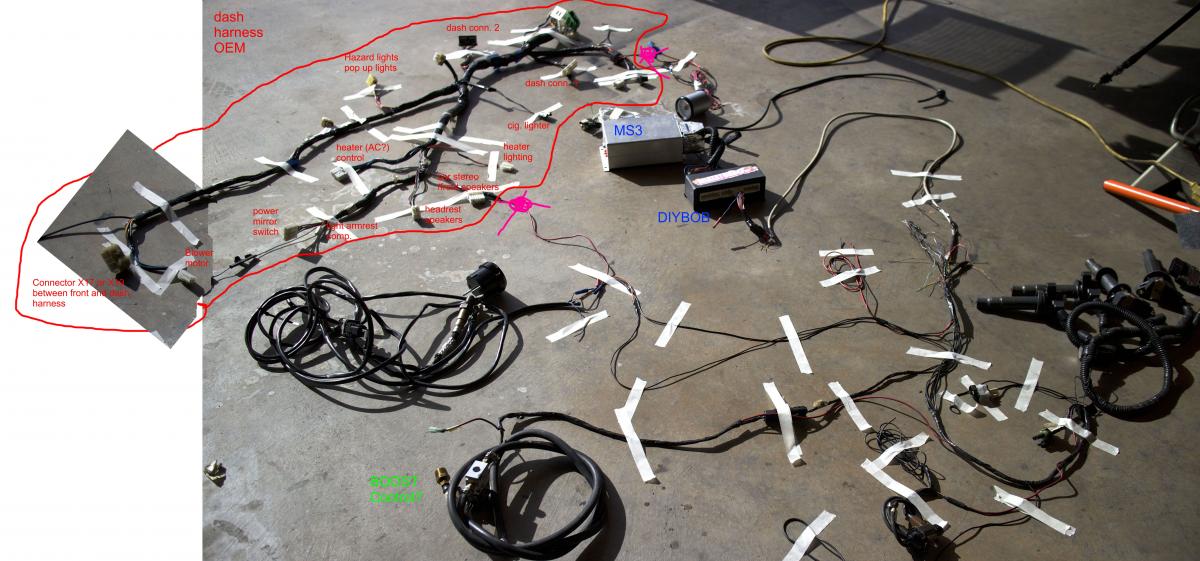
Here is the link to the OEM big picture:
http://www.ingenieure-reichel.de/upl...14/Jeff_v1.jpg
If I were you I would clean out the dash harness first - I marked the two things in PINK where I would try to remove the hacks (for boost gauge and the WB if I got this right)
I am a big fan of clean plug and play wiring - usually I try to make myself a plug-in harness for these extra things (we get to that in a second step...)
- I would like to have some (better) single pictures of the connectors on the right of the dash harness in the picture - these are the connectors for the fuse box, ignition switch etc. - to name them.
- Please open up the DIYBOB and get some pictures of the wiring from the MS3 harness inside the DIYBOB.
- Please unwrap the COP harness to see what is in there, lay it out seperatly and take some good pictures...
I think with the help of Brain, Dimitris and the other MS guru's here we will get this done!
First we need to divide OEM from "aftermarket" (aka hackjob)
I did try to name the connectors on the OEM dash-harness:
Here is the link to the OEM big picture:
http://www.ingenieure-reichel.de/upl...14/Jeff_v1.jpg
If I were you I would clean out the dash harness first - I marked the two things in PINK where I would try to remove the hacks (for boost gauge and the WB if I got this right)
I am a big fan of clean plug and play wiring - usually I try to make myself a plug-in harness for these extra things (we get to that in a second step...)
- I would like to have some (better) single pictures of the connectors on the right of the dash harness in the picture - these are the connectors for the fuse box, ignition switch etc. - to name them.
- Please open up the DIYBOB and get some pictures of the wiring from the MS3 harness inside the DIYBOB.
- Please unwrap the COP harness to see what is in there, lay it out seperatly and take some good pictures...
I think with the help of Brain, Dimitris and the other MS guru's here we will get this done!

Reply
 0
0

0
01-28-2014, 04:25 AM
#22
Elite Member
Join Date: Mar 2006
Location: Schwarzenberg, Germany
Posts: 1,554
Total Cats: 101
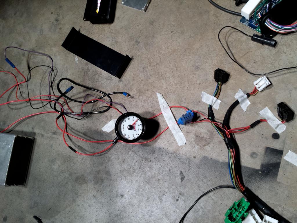
For the Boost gauge I would use such an adapter (you need one anyway if you will use an aftermarket headunit)
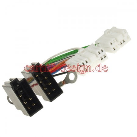
I would solder and heatshrink an extra connector into this adapter ( I tend to use computer power connectors for the interior stuff, because they are cheap and easy to get.)
Then you are able to make a little harness with the exact length that you need to your boost gauge location (for the gauge I think you might need switched +12V, ground, interior light 12V - all that should be on there)
and in the end everything can be plugged and pulled separately..
Here is a picture of my adapter for a headunit-less audio utilizing such an adaptor connector
I like to make things clean with some sleeve and heatshrink...
Reply
0
0
01-28-2014, 07:35 AM
#23
Boost Czar


iTrader: (62)
Join Date: May 2005
Location: Chantilly, VA
Posts: 79,494
Total Cats: 4,080
You need to cut it up to that point.
Otherwise, that's a normal spare connector used for extra inputs/outputs.
Looks like I unit I probably built using a DIYBOB. But you really need to rewire it from that extra connector for all the extras going to it. using at least 20g wire, 18g preferably.
and dont connect things using electrical tape.
Reply
0
0
01-28-2014, 07:42 AM
#24
Elite Member
Join Date: Mar 2006
Location: Schwarzenberg, Germany
Posts: 1,554
Total Cats: 101
The MS3 harness looks fine. Even that connector going out the 16 pin connector is okay. but then it goes into some wire loom that's maybe, what, 30 gauge wires?
You need to cut it up to that point.
Otherwise, that's a normal spare connector used for extra inputs/outputs.
You need to cut it up to that point.
Otherwise, that's a normal spare connector used for extra inputs/outputs.
I suggested to unwrap the COP harness, because maybe he could use some of that wiring...
If it is one of your units (I think Jeff suggested that before) - how would you have configured the extra connector for the "additional functions" (boost control? what else could this be?)
Reply
0
0
01-28-2014, 07:46 AM
#25
Boost Czar
iTrader: (62)
Join Date: May 2005
Location: Chantilly, VA
Posts: 79,494
Total Cats: 4,080
I typically put on it: spark c d, fuel c d, boost out, wbo2 in, anything else they might want when building.
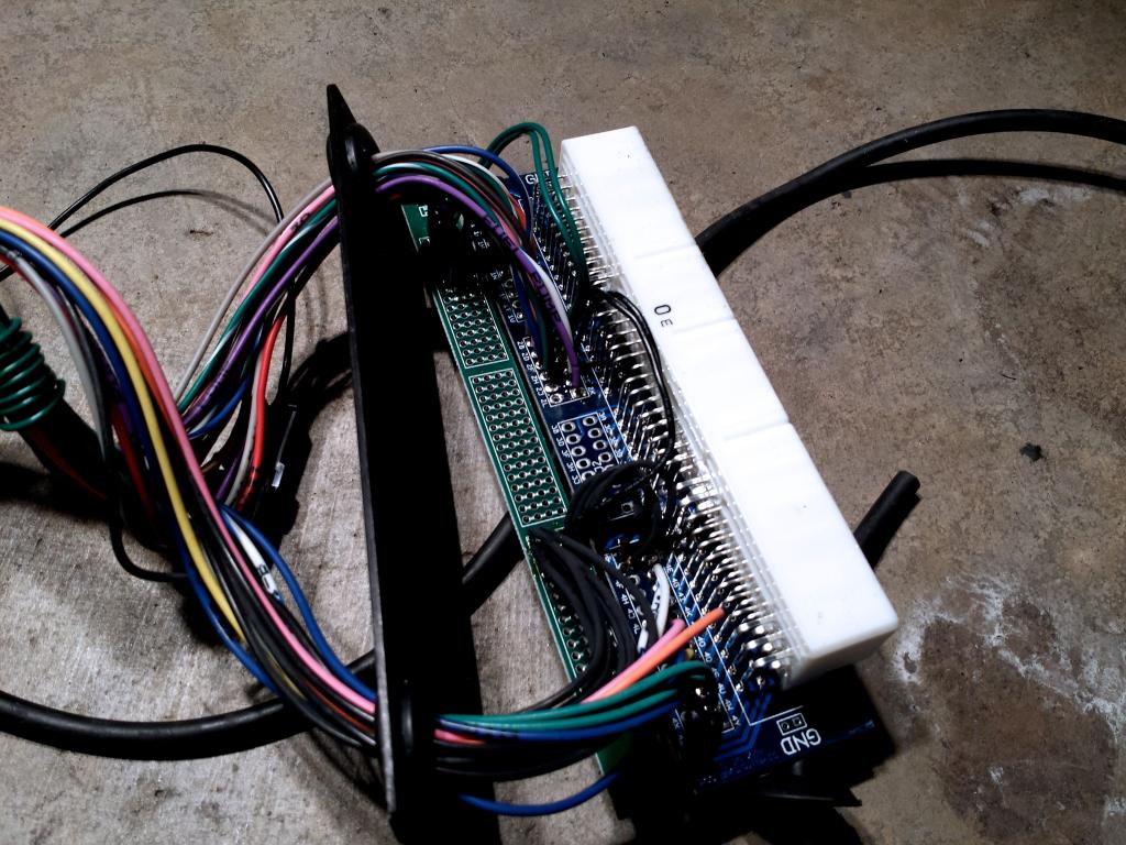
if you pop the cover off the DIYBOB and snap a shot of the wires going into the center connector we can easily see.
but after looking again, it doesn't look like my work. The only time I've used white connectors is if the wires are all black, like BTMiata posted. And when I do use color wires, I match the color coding on the ms3x wiring loom. So I'd never put a white, yellow, or orange wire on that connector.
but, again, we can figure out how it's wired if you pop the cover and we see what's going into it; assuming he wired the harness using the default color codes properly.
Reply
0
0
01-28-2014, 12:05 PM
#26
Elite Member
Thread Starter

Join Date: Oct 2013
Location: Cedar City, UT
Posts: 2,764
Total Cats: 951
You guys as always blow me away with how helpful you are. When I get down to my car this afternoon I'll strip some more electrical tape and take more detailed photos of the wires and the DIY-BOB sans cover.
Agreed on the no electrical tape for joining wires. I've got a soldering iron and 16/18 gauge wires(I plan to buy matching color wiring so there isn't a sudden jump in wire coloration) and a whole slew of shrink wrap covers.
Hopefully I can wire it as zaphod described with connectors so no more wiring has to be cut to feed it through the firewall.
Sorry Brain if I implied this was from you, no offense as I thought he bought the kit from you, but it looks like this was a DIY job.
Reply
0
0
01-28-2014, 12:20 PM
#27
Elite Member
Join Date: Mar 2006
Location: Schwarzenberg, Germany
Posts: 1,554
Total Cats: 101
@Jeff - you don't need to unwrap the OEM dash harness, in fact I think you can just remove the two hacks and fit it in the car.
I think you should have enough colour matched wire in your donor car..?
I think you should have enough colour matched wire in your donor car..?
Reply
0
0
01-28-2014, 12:22 PM
#28
Elite Member
Thread Starter
Join Date: Oct 2013
Location: Cedar City, UT
Posts: 2,764
Total Cats: 951
Sorry I should have specified unwrapping just the ms3/aftermarket wiring. The dash wiring I won't touch. Yeah I have the full 90' harness from the donor car sitting in a box.
Reply
0
0
01-28-2014, 12:25 PM
#30
Boost Czar
iTrader: (62)
Join Date: May 2005
Location: Chantilly, VA
Posts: 79,494
Total Cats: 4,080
I dunno if you did, at first glance it looked like I did build it, but after looking again, it doesn't look like my handy work. I could be wrong, but I think the only silver cased ms3x I ever made was my own, all black cases after the first batch in 2010.
Reply
0
0
01-29-2014, 05:50 AM
#32
Elite Member
Thread Starter
Join Date: Oct 2013
Location: Cedar City, UT
Posts: 2,764
Total Cats: 951
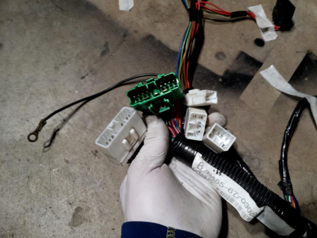
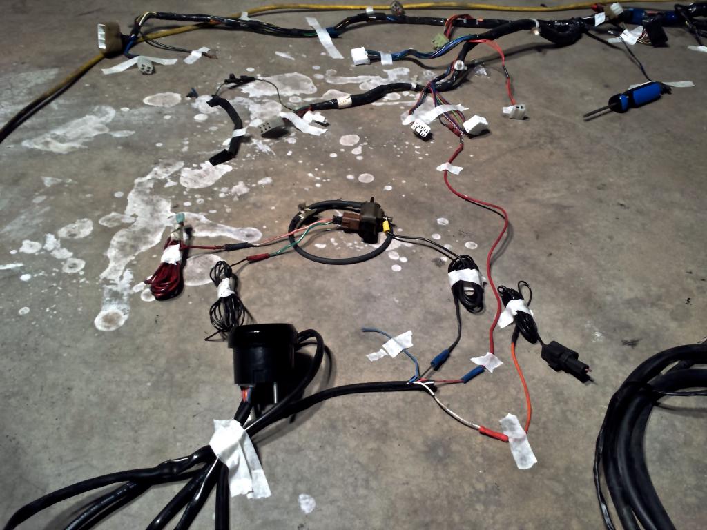
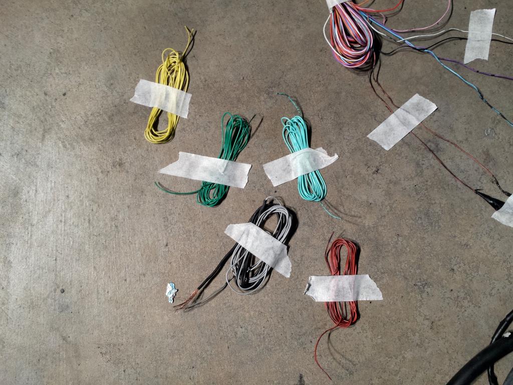
OK, I apologize in advance for the massive amounts of pictures.
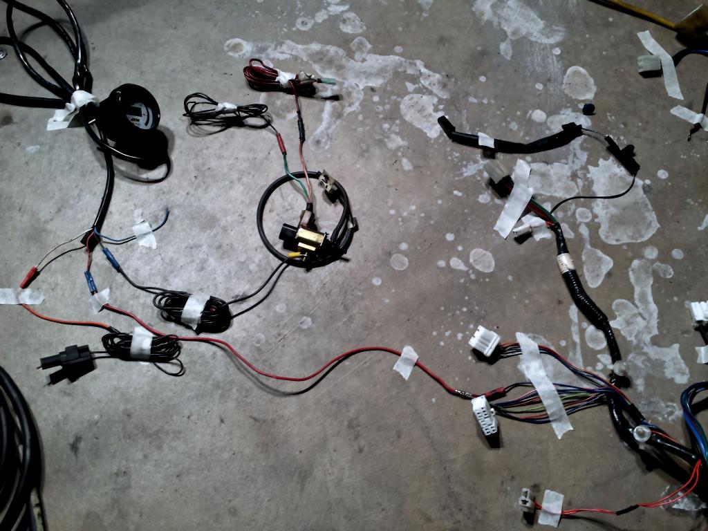
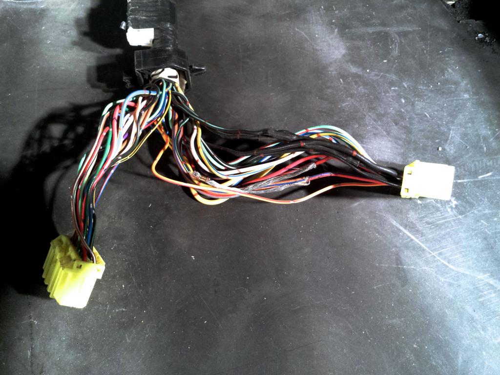
Dashboard harness.


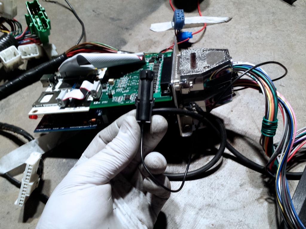
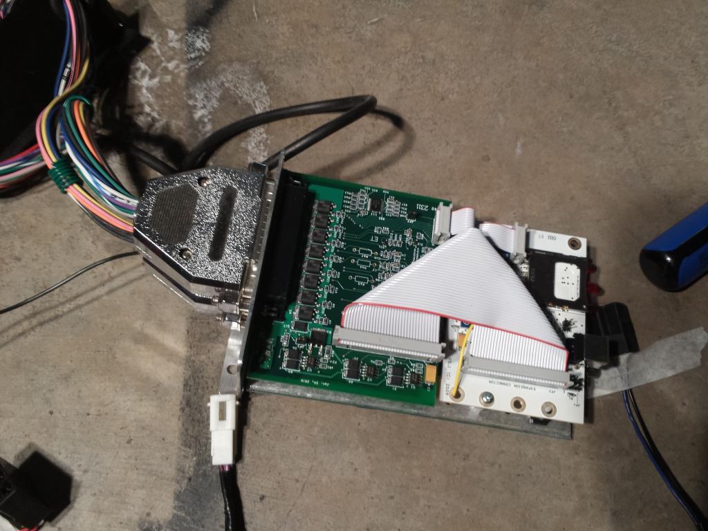
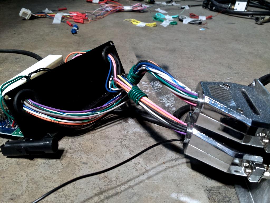
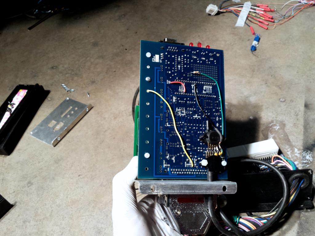
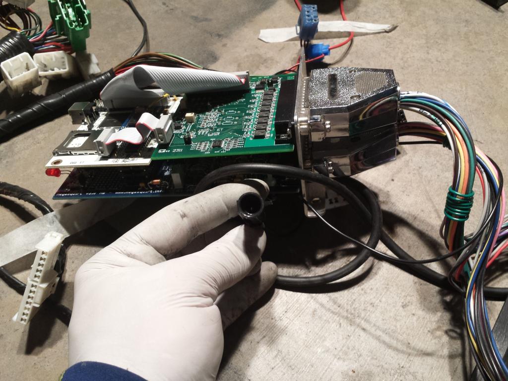
MS3 Board and DIYBOB


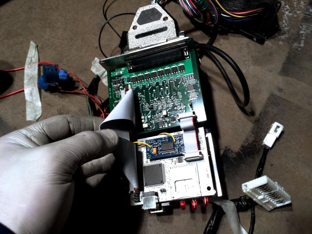


Wire code written on individual wires. The only ones that were blank were the black and white wires.
Classification:
Orange-IAT
Blue-TPS-SIG
Brown-PIN 36
Red-12 VDC
Yellow-Coolant
Teal/White-IAC2-A
Pink-O2
Brown #2-connected to black wire
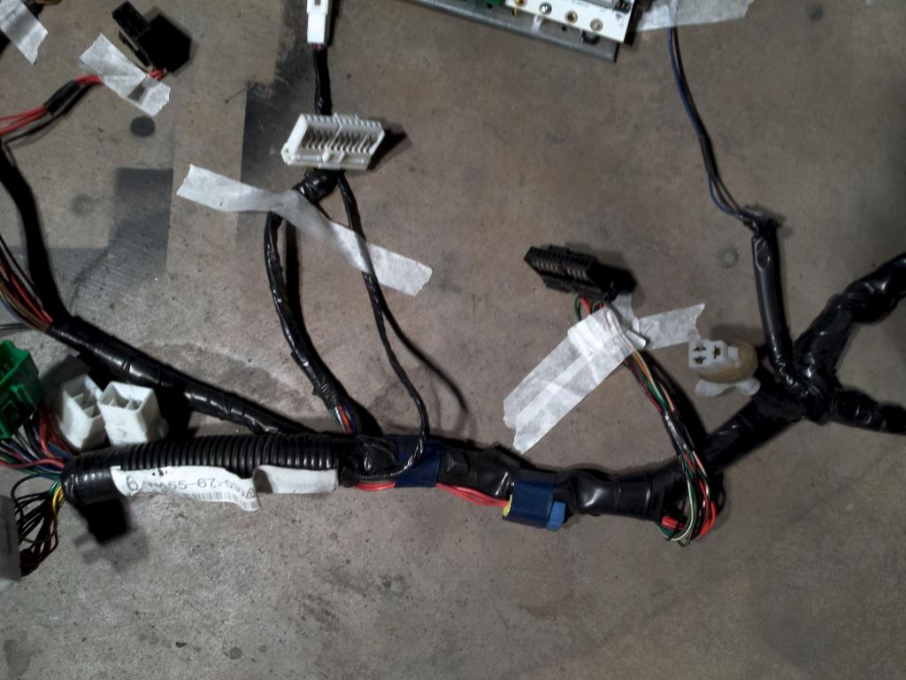
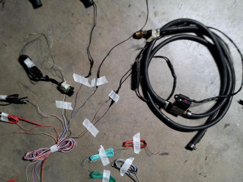
I stripped the shielding off the bundled cable and removed the "unused wires" to simplify the bundle and show more easily what is used and what isn't.
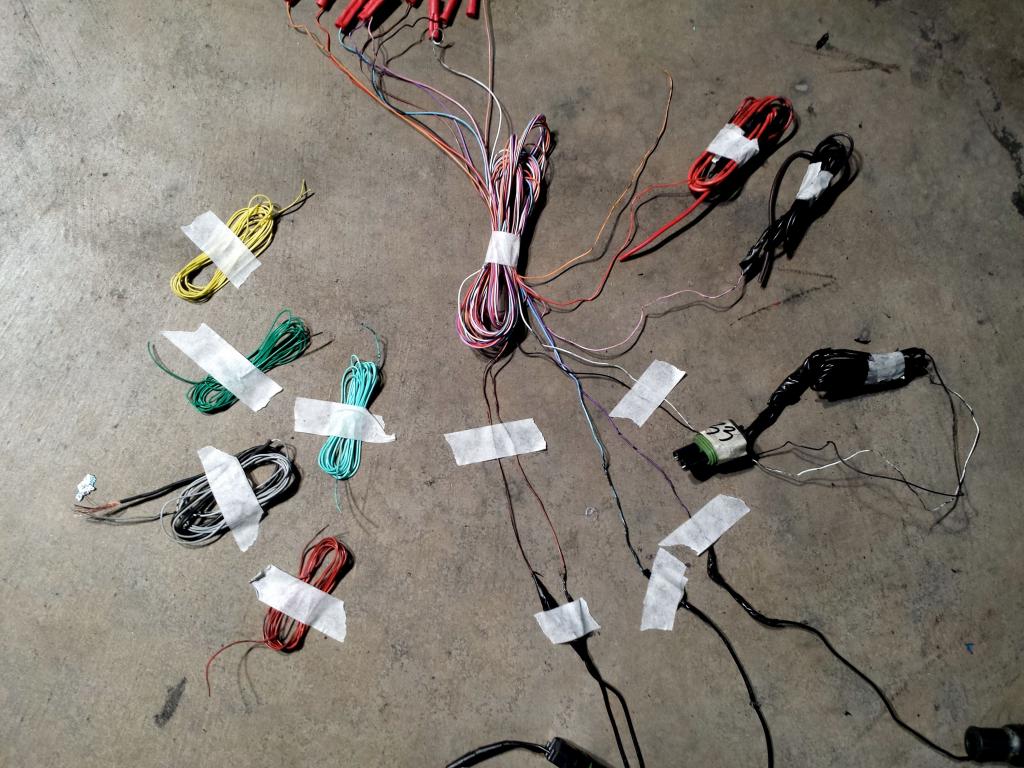

2 thin gauge brown wires feeding to the EBC

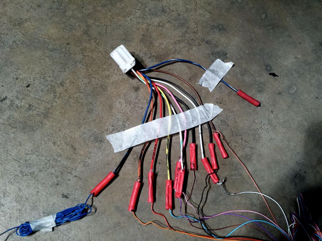
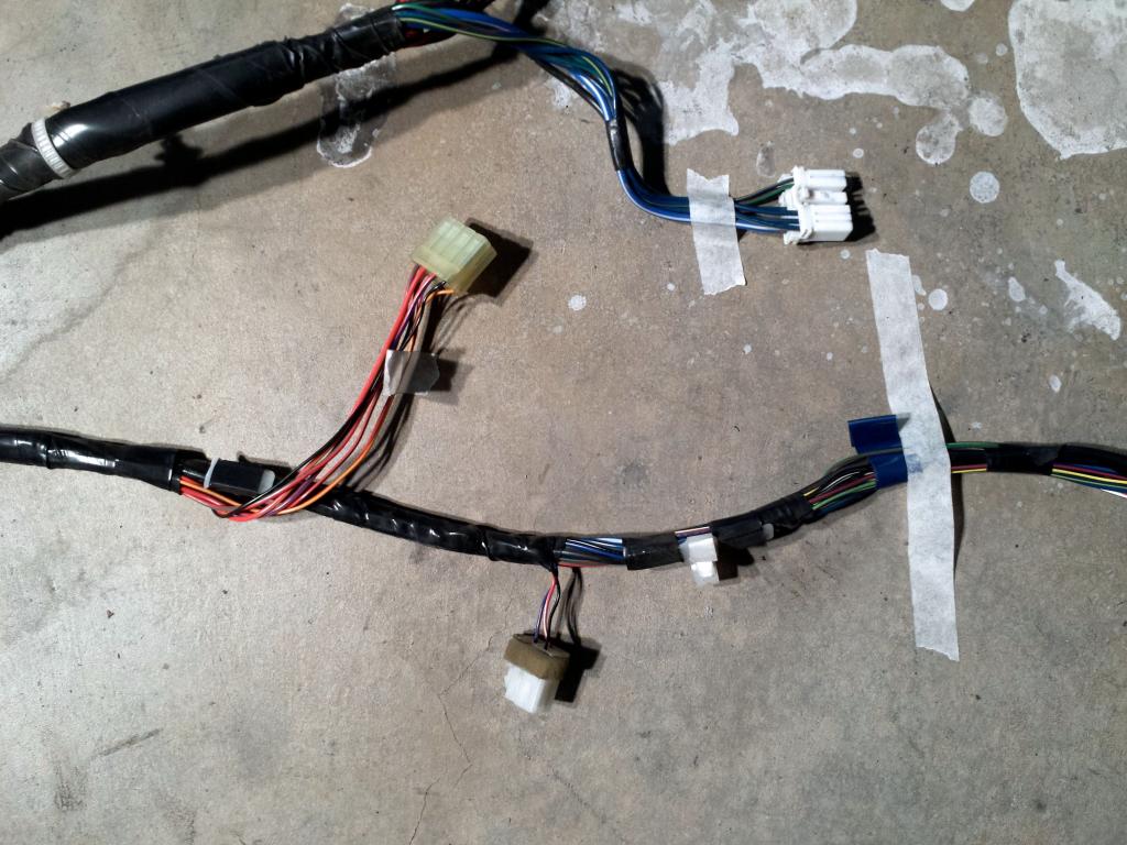
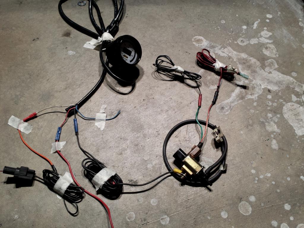
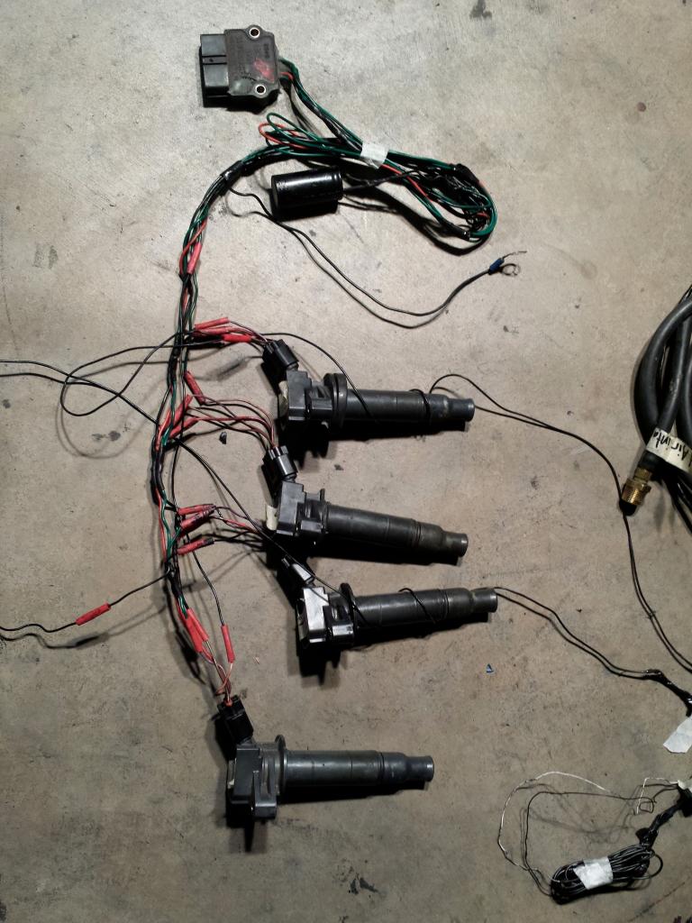
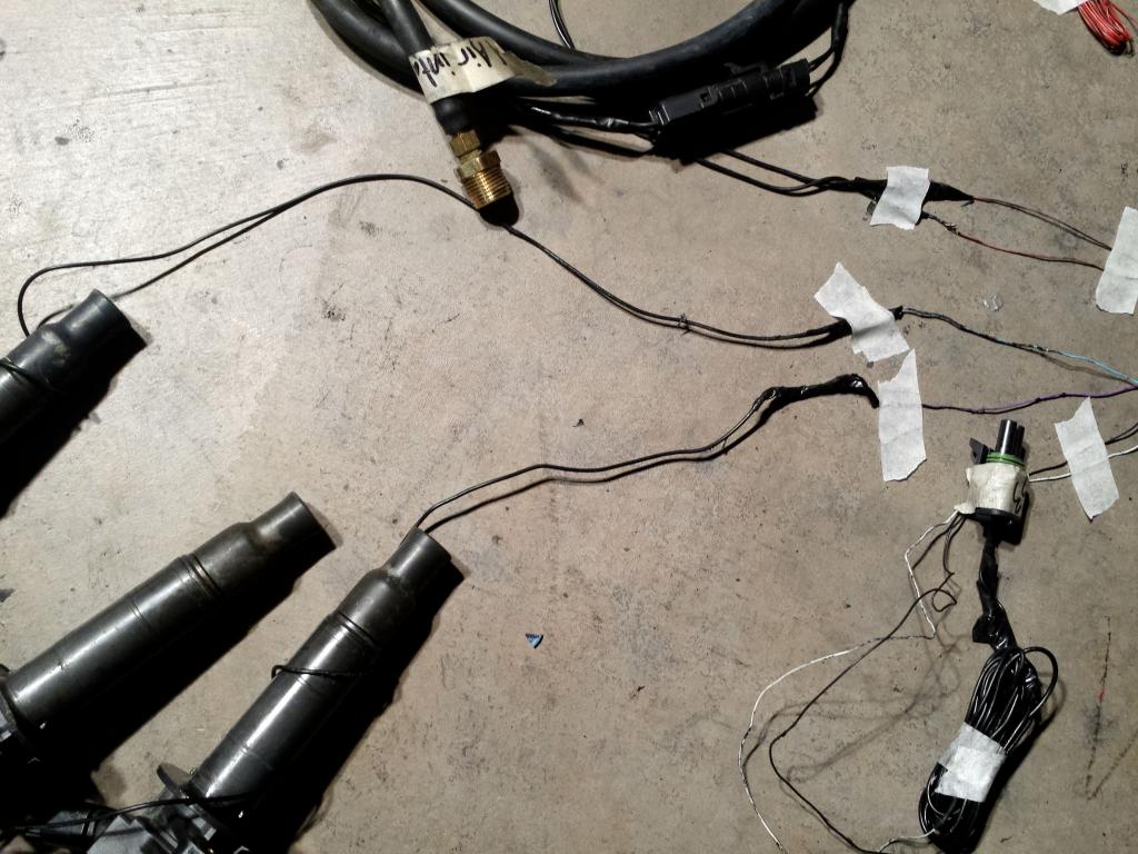
stripped electrical tape off COP Harness

Purple feeding into the #2 COP
Light Blue(which is connected to yellow for some odd reason) feeding #4 COP

White and black into this connector
Thick red gauge connected to thin red gauge
pink into thick black gauge wire which terminates into brown(hard to see in picture)
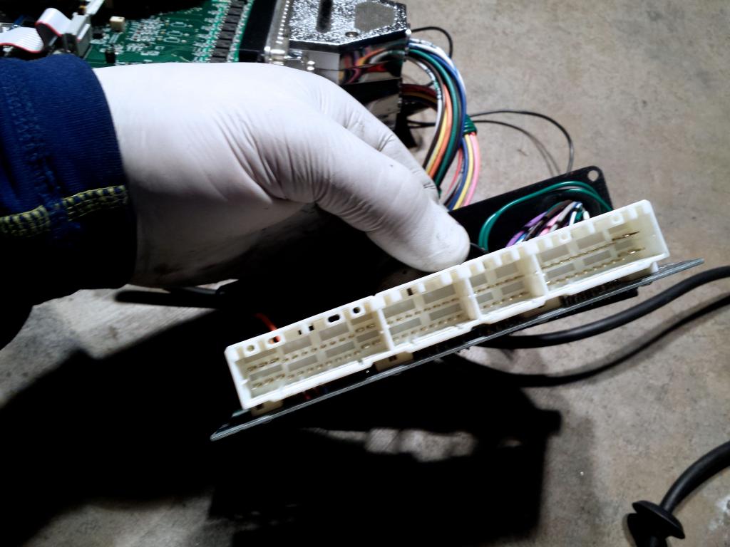
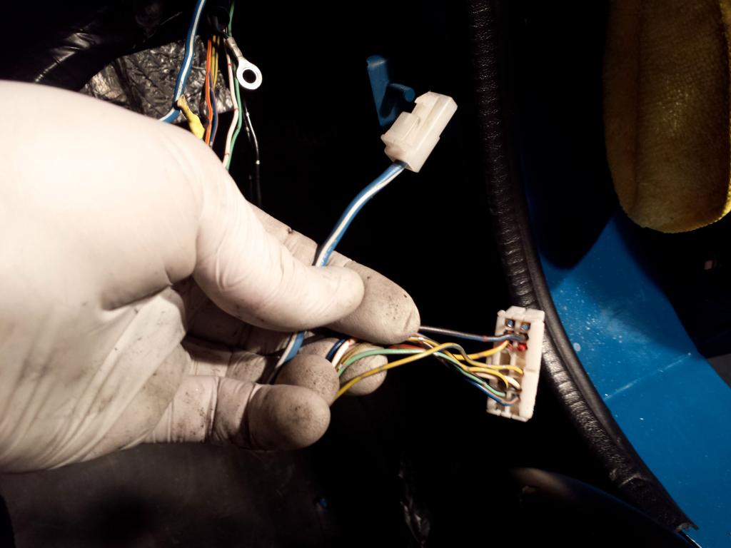
Firewall MS3X harness

Pretty sure this is the heater connector

If you need me to get a picture of something different or explain something further I can. I figured more info/pictures is better than fewer.
Dashboard harness.


MS3 Board and DIYBOB


Wire code written on individual wires. The only ones that were blank were the black and white wires.
Classification:
Orange-IAT
Blue-TPS-SIG
Brown-PIN 36
Red-12 VDC
Yellow-Coolant
Teal/White-IAC2-A
Pink-O2
Brown #2-connected to black wire

I stripped the shielding off the bundled cable and removed the "unused wires" to simplify the bundle and show more easily what is used and what isn't.


2 thin gauge brown wires feeding to the EBC

stripped electrical tape off COP Harness

Purple feeding into the #2 COP
Light Blue(which is connected to yellow for some odd reason) feeding #4 COP

White and black into this connector
Thick red gauge connected to thin red gauge
pink into thick black gauge wire which terminates into brown(hard to see in picture)

Firewall MS3X harness

Pretty sure this is the heater connector


If you need me to get a picture of something different or explain something further I can. I figured more info/pictures is better than fewer.
Reply
0
0
01-29-2014, 05:50 AM
#33
Elite Member
Thread Starter
Join Date: Oct 2013
Location: Cedar City, UT
Posts: 2,764
Total Cats: 951
OK, I apologize in advance for the massive amounts of pictures.
Dashboard harness.
MS3 Board and DIYBOB


Wire code written on individual wires. The only ones that were blank were the black and white wires.
Classification:
Orange-IAT
Blue-TPS-SIG
Brown-PIN 36
Red-12 VDC
Yellow-Coolant
Teal/White-IAC2-A
Pink-O2
Brown #2-connected to black wire

I stripped the shielding off the bundled cable and removed the "unused wires" to simplify the bundle and show more easily what is used and what isn't.


2 thin gauge brown wires feeding to the EBC
stripped electrical tape off COP Harness
Purple feeding into the #2 COP
Light Blue(which is connected to yellow for some odd reason) feeding #4 COP
White and black into this connector
Thick red gauge connected to thin red gauge
pink into thick black gauge wire which terminates into brown(hard to see in picture)

Firewall MS3X harness
Pretty sure this is the heater connector

If you need me to get a picture of something different or explain something further I can. I figured more info/pictures is better than fewer.
Dashboard harness.
MS3 Board and DIYBOB
Wire code written on individual wires. The only ones that were blank were the black and white wires.
Classification:
Orange-IAT
Blue-TPS-SIG
Brown-PIN 36
Red-12 VDC
Yellow-Coolant
Teal/White-IAC2-A
Pink-O2
Brown #2-connected to black wire
I stripped the shielding off the bundled cable and removed the "unused wires" to simplify the bundle and show more easily what is used and what isn't.
2 thin gauge brown wires feeding to the EBC
stripped electrical tape off COP Harness
Purple feeding into the #2 COP
Light Blue(which is connected to yellow for some odd reason) feeding #4 COP
White and black into this connector
Thick red gauge connected to thin red gauge
pink into thick black gauge wire which terminates into brown(hard to see in picture)
Firewall MS3X harness
Pretty sure this is the heater connector
If you need me to get a picture of something different or explain something further I can. I figured more info/pictures is better than fewer.
Reply
0
0
01-29-2014, 07:57 AM
#34
Boost Czar
iTrader: (62)
Join Date: May 2005
Location: Chantilly, VA
Posts: 79,494
Total Cats: 4,080
I probably built that. Might have been the first MS3x I put together for someone in 2010. Problem it was built using MS1/2 wiring loom so the wire color codes mean nothing without actually going back and tracing the pinouts to the DB37. I would have given the owner the pinout of that connector in the box it was shipped with, so you'll either have to go backwards and trace each to the db37 pin, or the other way around to the other devices on the receiving end.
That expander board needs a slight modification to it.
That expander board needs a slight modification to it.
Reply
0
0
01-29-2014, 08:32 AM
#35
Elite Member
Join Date: Mar 2006
Location: Schwarzenberg, Germany
Posts: 1,554
Total Cats: 101
Hi Jeff,
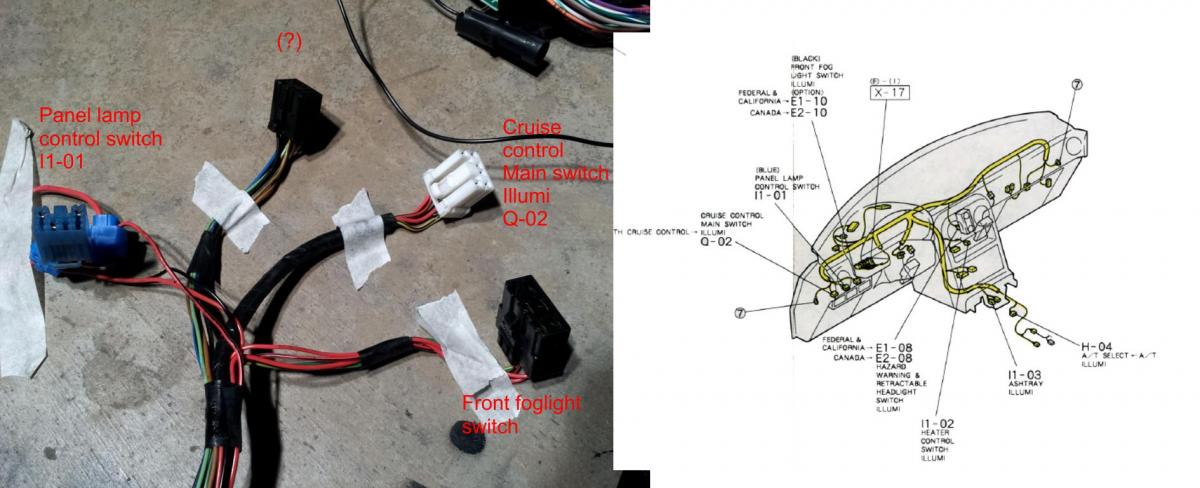
here are some more hint's about the OEM harness:
Some more on the main picture:

Two separate details:
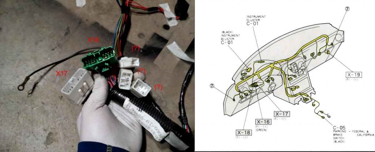
Please PM me your mail adress, I will send you a nice 1992 factory handbook, including some nice coloured wiring diagrams...
I have to do some real work now. :-)
Greets
here are some more hint's about the OEM harness:
Some more on the main picture:
Two separate details:
Please PM me your mail adress, I will send you a nice 1992 factory handbook, including some nice coloured wiring diagrams...
I have to do some real work now. :-)
Greets
Reply
0
0
01-29-2014, 03:42 PM
#36
Elite Member
Thread Starter
Join Date: Oct 2013
Location: Cedar City, UT
Posts: 2,764
Total Cats: 951
I probably built that. Might have been the first MS3x I put together for someone in 2010. Problem it was built using MS1/2 wiring loom so the wire color codes mean nothing without actually going back and tracing the pinouts to the DB37. I would have given the owner the pinout of that connector in the box it was shipped with, so you'll either have to go backwards and trace each to the db37 pin, or the other way around to the other devices on the receiving end.
That expander board needs a slight modification to it.
That expander board needs a slight modification to it.
https://www.dropbox.com/s/fjyg298eu8...on%20data.docx
https://www.dropbox.com/s/cnz19a8ee3...structions.xls
Believe these are the original wiring diagrams you or somebody gave the principle owner.
Reply
0
0
01-30-2014, 02:09 AM
#38
Elite Member
Join Date: Mar 2006
Location: Schwarzenberg, Germany
Posts: 1,554
Total Cats: 101
Purple feeding into the #2 COP
Light Blue(which is connected to yellow for some odd reason) feeding #4 COP
Light Blue(which is connected to yellow for some odd reason) feeding #4 COP
So these are your sequential ignition trigger wires for coil nr. 2 and 4. Trace them back to the 16pin connector at the DIYBOB and route 2 new decent gauge wires.
If I were you I would route them to the connector for the igniter - cut this connector and the gutted igniter (top of the lower picture) from the cop harness,
put a new waterproof connector with enough pins at that point and make a complete PNP cops harness.
@ Jeff - please help me out:
- what engine have you got for the car B6 or BP? Year?
- is it a California car?
@Brain - I suspect there should be wires for the sequential injection, where could they be at the 16pin connector or at the MS3 36pin connectors?
Last edited by Zaphod; 01-30-2014 at 02:24 AM.
Reply
1
1
01-30-2014, 03:22 AM
#39
Elite Member
Thread Starter
Join Date: Oct 2013
Location: Cedar City, UT
Posts: 2,764
Total Cats: 951
So these are your sequential ignition trigger wires for coil nr. 2 and 4. Trace them back to the 16pin connector at the DIYBOB and route 2 new decent gauge wires.
If I were you I would route them to the connector for the igniter - cut this connector and the gutted igniter (top of the lower picture) from the cop harness,
put a new waterproof connector with enough pins at that point and make a complete PNP cops harness.
@ Jeff - please help me out:
- what engine have you got for the car B6 or BP? Year?
- is it a California car?
95' BP engine.
Not a California car.
Engine specs:
Engine (R&R speed and machine Huntsville, AL receipts available):
Built ’95 1.8L with forged internals.
Billet oil pump gear
’99 miata head, ported, polished, 3 angle valve job, backcut valves
’99 miata intake manifold with active VICs controlled by the megasquirt computer
m-tuned dual feed fuel rail
750cc RC injectors
Adjustable intake cam gear
Toyota coil on plug conversion
Resistorless race plugs
Knock sensor
Engine Management:
Professionally built Megasquirt MS3x
Dual MAP sensors
Sequential fuel
Sequential spark
Knock module
Closed loop idle control
Closed loop boost control
Fan control
AEM WBo2 sensor
Hope that helps.
What connectors should I use for the COP Harness? I have the entire spare harness from the donor car I can salvage from if necessary.
Reply
0
0
01-30-2014, 04:17 AM
#40
Elite Member
Join Date: Mar 2006
Location: Schwarzenberg, Germany
Posts: 1,554
Total Cats: 101
What connectors should I use for the COP Harness? I have the entire spare harness from the donor car I can salvage from if necessary.
I used weatherpack(?) connectors with new pins and seals, you can get them cheap...
Reply
0
0


