Homebrew crank trigger wheel
 08-14-2009, 10:21 PM
#21
Junior Member
Thread Starter
Join Date: Aug 2008
Location: Boston
Posts: 223
Total Cats: 0
Either I'm not being clear or I am still missing the point. What I mean by the error being constant from revolution to revolution is that the ignition timing for any given advance value will be off by the same error every time that advance value is used. There may be more than one actual degree between 14 and 15 degrees of requested advance, and less than one actual degree between 15 and 16 degrees of requested advance, but the errors will be consistent -- for any given value of intended advance, spark will occur at the same point in the engine cycle every time even with an unevenly spaced wheel. (Or at least it will be repeatable to the same degree as it would be with a perfect wheel.)
Your explanation of the MS2 trigger algorithm matches how I assumed it worked.
Your explanation of the MS2 trigger algorithm matches how I assumed it worked.

Reply
 0
0

0
08-14-2009, 11:10 PM
#22
Boost Pope


iTrader: (8)
Join Date: Sep 2005
Location: Chicago. (The less-murder part.)
Posts: 33,027
Total Cats: 6,592
Ah, I understand what you're describing now, and yes, I'd think that the error at any given RPM and MAP intersection would always be consistent, though it will potentially vary with either MAP or RPM. Put in more useful terms, the error will be consistent for any given timing advance.
Honestly though, I don't see this as such a big deal. Even with the potential for 2 degrees of error, it is so much more accurate than the stock '90-'97 configuration that belaboring the point is academic.
I stand by my original opinion- this is a cool thing.
Honestly though, I don't see this as such a big deal. Even with the potential for 2 degrees of error, it is so much more accurate than the stock '90-'97 configuration that belaboring the point is academic.
I stand by my original opinion- this is a cool thing.
Reply
0
0
08-15-2009, 12:57 AM
#23
Cpt. Slow
iTrader: (25)
Join Date: Oct 2005
Location: Oregon City, OR
Posts: 14,189
Total Cats: 1,135
Don't you guys wish you had one of these?
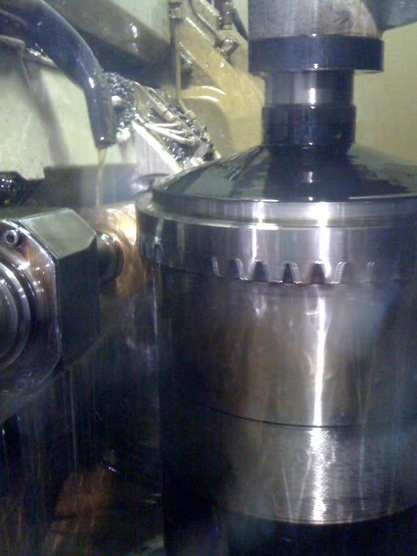
That's a 54 tooth 4 dp, with a .500" rough depth, .040" finish depth, all cut within 30 minutes.
Something like that trigger wheel (which would have near zero error) could be cut for your (I'm on bandaids still :() purposes (finish wouldn't matter, its not mating with anything) in about 10 minutes. And that would probably be a stack of 5 or 6, to help with rigidity.
If you got me the lathe'd blanks and tooth specs I could easily sneak a couple in next time I run a shaft job. Just something to keep in mind.
Reply
0
0
08-15-2009, 10:25 AM
#24
Boost Pope
iTrader: (8)
Join Date: Sep 2005
Location: Chicago. (The less-murder part.)
Posts: 33,027
Total Cats: 6,592

If only that damn wheel was flat, this would be a no-brainer. OTOH, I'm guessing we could probably scavenge them from junkyards for relatively cheap. So far as I can tell, the NA and NB wheels are identical except for the tooth profile.
Would the existing teeth have to be lathed off first, or can toothbot do that process as well? I am latheless at the moment.
Reply
0
0
08-15-2009, 12:49 PM
#25
Junior Member
Thread Starter
Join Date: Aug 2008
Location: Boston
Posts: 223
Total Cats: 0
Curly, I don't think that would fit in my garage 
Anyway, I built the adaptive VR conditioner yesterday and tested it out. I am really impressed. With 1/8" gap (huge) it can find edges at 100 RPM.
Raw VR signal at top, logic output of MAX9926 at bottom:

Note that the crappy looking signal has only a few hundred millivolts of swing.
1/8" gap. Much larger than necessary mechanically:

More normal looking signal with 5v of swing:

(Interesting to note that the signal looks a lot different than the 1996 wheel signal. I guess they wanted to use really simple signal conditioning circuitry.)
Test PCB:

Anyway, I built the adaptive VR conditioner yesterday and tested it out. I am really impressed. With 1/8" gap (huge) it can find edges at 100 RPM.
Raw VR signal at top, logic output of MAX9926 at bottom:
Note that the crappy looking signal has only a few hundred millivolts of swing.
1/8" gap. Much larger than necessary mechanically:
More normal looking signal with 5v of swing:
(Interesting to note that the signal looks a lot different than the 1996 wheel signal. I guess they wanted to use really simple signal conditioning circuitry.)
Test PCB:
Reply
0
0
08-15-2009, 12:56 PM
#26
Cpt. Slow
iTrader: (25)
Join Date: Oct 2005
Location: Oregon City, OR
Posts: 14,189
Total Cats: 1,135
Nice looking machine you've got there.
If only that damn wheel was flat, this would be a no-brainer. OTOH, I'm guessing we could probably scavenge them from junkyards for relatively cheap. So far as I can tell, the NA and NB wheels are identical except for the tooth profile.
Would the existing teeth have to be lathed off first, or can toothbot do that process as well? I am latheless at the moment.
That's why I said I'd need the gear blanks ready to go if I were to run any, the hobing is the easy part.
Whats the side profile look like with one of these? There's no way to make them flat?
Reply
0
0
08-15-2009, 01:00 PM
#27
Boost Pope
iTrader: (8)
Join Date: Sep 2005
Location: Chicago. (The less-murder part.)
Posts: 33,027
Total Cats: 6,592
Wow, I wish I'd known about that Maxim IC when I did mine. I tried using an LM1815N, but I could never get the damn thing to stop missing teeth whenever there was a drop in peak positive amplitude below a certain theshold from one tooth to the next:

Wound up just building a comparator circuit, and it works fine, but this would have saved a lot of time.
Wound up just building a comparator circuit, and it works fine, but this would have saved a lot of time.
Reply
0
0
08-15-2009, 01:57 PM
#28
Joe,
Comparator? Do post a schematic! I'm quite curious what you used. It's funny the stock MS chip is that bad. It's also funny your output is. :-)
Interestingly, I DID raid a junkyard and get a stock wheel and weld it to a friend's Mazda wheel. I was drunk while I did it, but, after some balancing, there wasn't a lot to worry about. Anyway, just saying it's viable.
Good question, that last one.
Same with my OEM set up. It's worst at idle, actually. Which, I guess makes sense, you're far off from the reference. One I get over 2000 rpm it's very well behaved, higher than that and it's dead dead solid. I have to slow the motor down to convince myself anything is actually moving and that the strobe is not just a dim light on a stationary object. I've been tempted to touch the wheel before at 6,000 rpm.
Just how much software are you going to write, software which has its own overhead, bugs, and oversightes, to get around 1) Buying at $30 wheel, or 2) Just using the perfectly fine wheel Mazda put on there?
That's like old smog checks - the reason there are so many visual checks is because they couldn't really test all conditions. With a fully functioning system, you tune once per RPM/MAP and know (ha!) that compensations for barometeric fluctuations, air temps, throttle rate-of-change, etc are all being correctly applied. Once you screw up the base map by faking it (a faking it you don't have to do I remind you), then all these corrections are also based on bad information. And adding 1 degree of timing which turns out to be 2 is too much.
Yes, ok, so you're saying, what's the big deal? All these guys who do real tuning, who make actually fast cars, they DEMAND a half a degree timing accuracy. Having been involved in a project where this was discussed at large (many want within a tenth of a degree), I can tell you that no one I've talked to who actually tunes fast cars will settle for a system with 1 degree of error.
If cylinders 1/4 and 2/3 are off by a degree, that means your maps cannot accommodate it without a full sequential system. If you're going to write all your own software, redo half the hardware, I'm starting to miss the point of using the megasquirt, which let's face it - only has one thing going for it - that it works without thinking about it as long as you do what they tell you.
As an aside, I had a Link Piggyback. They said regularly not to run more than 9 psi with it, because the engines can't handle it. And yes, I too went through a set or two of rods because I was running 11 or 12 psi. FM makes no bones about it, if you want higher boost, run a Hydra, because you get better control over timing and fuel. And yes, their cars pick up tens of horsepower because of this tight control.
If you tune your engine to the knock threshold, and one side has timing retarded relative to the other, you're gone to be running suboptimally. It's a basic fact of design margin, you need to be one full tolerance away from the limit to have a hope of being safe.
Here's an idea, does your o-scope do decent logging? Give the wheel a spin, look at a full revolution (ideally a few) and see how far apart the teeth are, from a practical point of view.
Comparator? Do post a schematic! I'm quite curious what you used. It's funny the stock MS chip is that bad. It's also funny your output is. :-)
Interestingly, I DID raid a junkyard and get a stock wheel and weld it to a friend's Mazda wheel. I was drunk while I did it, but, after some balancing, there wasn't a lot to worry about. Anyway, just saying it's viable.
With my current setup, jitter is about +/- 1� worst-case.
That's a good point, but it is still a constant error from revolution to revolution. 1/4 spark may be a degree off from 2/3, but it will be the same degree off every time. I don't think that is a major problem, and it could be accounted for in custom software if it was a problem.
Right. Some degrees will be larger than others. But again, as long as the error is the same every revolution, the tuning parameters will be consistently applied.
Yes, ok, so you're saying, what's the big deal? All these guys who do real tuning, who make actually fast cars, they DEMAND a half a degree timing accuracy. Having been involved in a project where this was discussed at large (many want within a tenth of a degree), I can tell you that no one I've talked to who actually tunes fast cars will settle for a system with 1 degree of error.
If cylinders 1/4 and 2/3 are off by a degree, that means your maps cannot accommodate it without a full sequential system. If you're going to write all your own software, redo half the hardware, I'm starting to miss the point of using the megasquirt, which let's face it - only has one thing going for it - that it works without thinking about it as long as you do what they tell you.
As an aside, I had a Link Piggyback. They said regularly not to run more than 9 psi with it, because the engines can't handle it. And yes, I too went through a set or two of rods because I was running 11 or 12 psi. FM makes no bones about it, if you want higher boost, run a Hydra, because you get better control over timing and fuel. And yes, their cars pick up tens of horsepower because of this tight control.
If you tune your engine to the knock threshold, and one side has timing retarded relative to the other, you're gone to be running suboptimally. It's a basic fact of design margin, you need to be one full tolerance away from the limit to have a hope of being safe.
Here's an idea, does your o-scope do decent logging? Give the wheel a spin, look at a full revolution (ideally a few) and see how far apart the teeth are, from a practical point of view.
Reply
0
0

Thread
Thread Starter
Forum
Replies
Last Post
Frank_and_Beans
Supercharger Discussion
13
09-12-2016 08:17 PM
Greasyman
General Miata Chat
2
09-28-2015 10:44 AM


