MegaSquirtSanta - Custom Modifications / Firmware
 11-01-2011, 05:18 PM
#21
Junior Member
Thread Starter
iTrader: (1)

Join Date: Jun 2011
Location: Australia
Posts: 178
Total Cats: 3
Ok, so this "Idle valve duty hystersis, based on RPM" has got Santa intrigued... tell me more... how do you see this working.... what do you want changed?
Cheers,
MegaSquirtSanta
PS - as you've all been good boys/girls, I've worked some magic on a release that has Clutch/Neutral input PE0 PID lockout so you can dribble along in gear and when you drop the clutch, only then it jumps into PID... Very Niiiiiccceee !!
Cheers,
MegaSquirtSanta
PS - as you've all been good boys/girls, I've worked some magic on a release that has Clutch/Neutral input PE0 PID lockout so you can dribble along in gear and when you drop the clutch, only then it jumps into PID... Very Niiiiiccceee !!

Reply
 0
0

0
 11-01-2011, 07:03 PM
#25
Junior Member

Join Date: Apr 2010
Posts: 107
Total Cats: 0
Awesome. Can this be combined with a clutch launch control input on FLEX/PE0? I think a bunch of us may be wired up this way already.
Reply
0
0
11-01-2011, 07:45 PM
#26
Junior Member
Thread Starter
iTrader: (1)
Join Date: Jun 2011
Location: Australia
Posts: 178
Total Cats: 3
The way I remember it what helped before was a user-defined deadband around the RPM target, so once an RPM within the band was achieved it stop changing the idle valve duty until the rpm fell out of the band. If you had an idle target of 900 RPM set up and a +- 50 band at 30% it wouldn't move from 30% until you went over 950 RPM or below 850. I'm not sure how that was implemented exactly (maybe a floor on the instantaneous error term) but when mariob did it it prevented some of the oscillation some of us experienced in (what should have been) steady-state.
Greg - do you need this mod or is this a tuning issue with too much D?
Cheers,
MegaSquirtSanta

Reply
0
0
11-01-2011, 08:01 PM
#27
Junior Member

Join Date: Jun 2007
Posts: 411
Total Cats: 0
Anyway I have suggestions which I think will make it much better, IMHO.
1. Make the deadband individually configurable above and below the target, instead of equally added to both sides of the target. That way, we avoid delayed action vs droop, but still get some benefit of a fatter target. Or if the user wants it equal, he can do so.
2. Change the output of the closed loop PID within the deadband by a user defined damping factor! If you want no reaction within the deadband, use a 100% damping factor. If you want PID to just be less jumpy, use 50% or whatever factor you wish.

Oh, and the antistall feature was pretty nice, as a failsafe feature. Below a set rpm (say <400), the idle valve would open up to prevent a stall. Did wonders for your peace of mind knowing that you couldn't stall (most of the time).
Last edited by Greg G; 11-01-2011 at 11:45 PM.
Reply
0
0
11-02-2011, 05:19 PM
#28
Newb

Join Date: Feb 2011
Location: Oxford UK
Posts: 39
Total Cats: 0
The advantage of having the dead zone is that you can run aggressive PID settings to drive the idle duty quickly, but once you're close enough to your idle target the PID stops moving the valve which helps stop oscillation, which would make idle tuning a lot easier. It'd also make it a lot easier to get a car running on MS2 and functional faster, which can only be a good thing.
It was in the mariob tweaks but license terms couldn't be agreed so it never made it into the release code.
I'm not 100% sure how the current PID code works, if I'm right then it just loops constantly whilst watching the PID parameters. If so then a simple If, Then, Else based on a Min Idle RPM < current RPM < Max Idle RPM should be enough.
Reply
0
0
11-02-2011, 07:12 PM
#29
Junior Member
Join Date: Jun 2007
Posts: 411
Total Cats: 0
Hmmm. Perhaps another condition for activation of the dead zone is a minimum RPMdot value. That way, the dead zone activates to stabilize idle when near target, but does not impede the action against fast changes (sudden droops).
Reply
0
0
11-03-2011, 01:08 AM
#31
Junior Member
Join Date: Jun 2007
Posts: 411
Total Cats: 0
I discussed this with Jason, and his idea seems better! It's a moving hysteresis window, applied to the valve, not the rpm target. Basically it smoothness the signal by not allowing it to jumps of far from a set-width window, which constantly adjusts based on the input. I'll let him do the explaining. Basically, it calms the jittery valve duty but does not affect pid action.
Here's his explanation (he discusses tps dot but it will be applied in our case to idle valve duty output):
Here's his explanation (he discusses tps dot but it will be applied in our case to idle valve duty output):
robs wrote:
Been a while since I posted anything code/design related, the last being the epic on "noisy" RPM values. Like in that thread, I am running the risk of being told that I'm looking at this stuff too closely and, once again, I'm going to be saying that it's not me but the MS code that's looking too closely.
I'm sure I'm not the only one here to look at the TP values at idle, fluctuating around between 0 and 1. Like this:
TP.jpg
and compare it with the corresponding tpsDOT values which seem very volatile for such small movements. Like this:
*** Jason starts here****
The best filtering for a given signal depends on the characteristics of the signal and the noise.
One type of filtering that works very well for the type of noise in the first post is a moving hysteretic window.
The window has a certain "width" and it gets "pushed" up or down by the data. To push up, it has to exceed the upper part of the window. To push down, it has to be lower than the lower part of the window. The output is the location of the window. This type of filtering works very well for coolant and air temps too.
For a window width of 2 it will go like this. Input data is a slow rise with noise on it
in out
10 10
11 11
10 11
12 12
10 12
9 11
12 12
13 13
11 13
14 14
15 15
13 15
and so on
Last edited by Greg G; 11-03-2011 at 01:21 AM.
Reply
0
0
 11-03-2011, 04:10 PM
#33
Elite Member

Join Date: Jul 2005
Posts: 6,420
Total Cats: 84
Pls. read my posts in this thread:
http://www.msextra.com/forums/viewto...301785#p301785
The hysteretic window is good for filtering the *output* of a feedback loop, such as the PWM signal that goes to the idle solenoid. It greatly reduces any "shivering" or hunting around of the solenoid. It is a bad idea to use it for the input signal such as RPM. Greg found this out firsthand.
The appropriate filter for an *input* signal, such as the RPM signal for the idle control loop, or the MAP signal, is a "Bessel" lopass filter.
I gave a sample in the above msextra link.
Reply
0
0
11-04-2011, 12:49 AM
#35
Junior Member
Join Date: Jun 2007
Posts: 411
Total Cats: 0
Ooooh I like it. My valve duty graph looks exactly like that! Smoothening the output might just be the ticket to a calm yet reactive steady state idle.
Reposting the explanation:
See pictures explain it so much better 
Reposting the explanation:
The moving window hysteresis filter is good for filtering an output signal that goes to an actuator, such as the idle solenoid.
It's not good for filtering an input signal such as RPM.
See below example.
The red trace is the "jittery" output signal. The blue traces are the top and bottom of the window. The signal can push the "top" of the window up, or push the "bottom" of the window down. The filtered output is the center of the window. (X's)
Notice that the red signal jitters up or down with every sample. Imagine this is your idle solenoid. It's constantly moving.
In contrast, the window has periods where it is flat - it doesn't change for a couple of cycles. So the idle solenoid doesn't jitter as much. It will move in fits and starts, but it stays put a good percentage of the time. In this example, >50% of the time.
Reply
0
0
11-04-2011, 01:27 PM
#36
Elite Member
Join Date: Jul 2005
Posts: 6,420
Total Cats: 84
Santa,
If I may suggest ... the whole idle strategy needs to be re-architected.
The main changes I suggest are these:
- the idle_duty% is: lookup table values + feedforward values + PID
- PID always turned off if the wheels are connected to engine, but all lookup tables and feedforward *always* active in determining duty%
- TPS > 0 exits PID
- Whenever PID (closed loop) exits, I is *always* reset to zero
- the output of I has to have a + and a - limit. That is, e.g. it can never add mroe than say, 15%, or remove more than 10% from the output.
- Whenever closed loop is re-entered, I *always* has to be reset to zero
- Whenever closed loop is re-entered there should be a "closed loop re-entry target RPM adder". This stays for like 1 sec, and then the target ramps down to the normal target over say, 3 sec. For example, target will initially be 1200 RPM upon re-entry. This target will stay for 1 sec, then ramp down to 850 over 3 seconds. This will solve the stopping-at-a-stop-sign idle dip, and it will also work well for stepping on the clutch when lugging the engine at 600 RPM.
- having a good set of feedforward setups is critical: a/c, voltage, IAT, etc.
Reply
0
0
11-04-2011, 07:29 PM
#37
Junior Member
Join Date: Jun 2007
Posts: 411
Total Cats: 0
Jason and I had a long discussion last night about this. Mainly because my supercharger belt had broken on the dyno, so I had to drive home through a major traffic jam with no AC. So I had a good hour's data of crawling through stop and go traffic to observe the low speed stop and go behavior of the pid code. My car has no radio, so all I could do to entertain myself was watch the idle duty (how sad is that)
So yes I agree that:
1. The conditions for closed loop entry are a big factor. Having it active while in gear, especially in 'parking lot' driving conditions- say you are decelerating slowly driving up a slight slope, and enter closed loop. You slip the clutch to maintain a slow speed going up that slope. That drives the pid crazy and it drives the idle valve duty higher and higher. Then you let up the clutch to stop, bam! Idle shoots up to 1,600 or something like that.
The reverse is true if youre cruising down to a stop and you enter closed loop early- the pid code wants to close the valve so drops it to minumum value. When you clutch in, you get a droop.
These actions are mainly driven by the I term, and is called "integral windup". Since it never seems to get to target, it keeps adding and adding or subtracting and subtracting. This is solved in 3 ways- put a maximum limit on the I output, reset I on closed loop exit, and modify the entry to closed loop with a hardware mod. This can be a vss input(ms3), or a clutch neutral switch condition for closed loop entry (great mod pioneered by reverant).
2. The calculation of the idle valve duty must be improved over the current 'last known good' value, and correlated to the clt table (like warmup only mode) plus the feedforward factors like battery voltage correction, mat correction, AC input. You want to enter closed loop idle at a duty value spot on for the conditions, to get smooth entry. Presently it's something like "get it in the ballpark and let pid deal with it". Perhaps just a straight clt table lookup modified by the various feedforward adders will give a better consistent value. Like the best of both world between warmup only and close loop idle modes...
The code is pretty good already, but I think these improvements will have a real tangible effect and bring it to near oem level.
Found some good reading here:
http://chriswilson.tv/PID.pdf
Last edited by Greg G; 11-12-2011 at 09:43 PM.
Reply
0
0
11-05-2011, 08:35 AM
#38
Newb
Join Date: Feb 2011
Location: Oxford UK
Posts: 39
Total Cats: 0
Another thing that the mariob code did was to use the open loop idle duty table to provide a known good value. The use of that table in conjunction with some pre-determined adders for A/C, headlights, etc may be a good place to start, and uses something that's already in the code
Reply
0
0
11-05-2011, 01:13 PM
#39
Elite Member
Join Date: Jul 2005
Posts: 6,420
Total Cats: 84
Note the following:
"Last known good value" alludes the last 'I' value be used. This is a mistake, it should be reset to zero.
"Last known value" alludes to "remembering" some kind of last value. Not really any different.
Here is why freezing or remembering the I value is bad.
For example, I is at -10% for some reason idling at a light, then you drive off.
You then encounter traffic and crawl the car in 1st gear with foot off of clutch, and let RPM drop to 700 RPM. You then push in the clutch. If you use I=-10%, the engine will die. You are better off with I=0. When PID is re-entered with RPM=700, the P will instantly add lots of duty cycle to get the RPM to rise rapidly.
Or if RPM is dropping very rapidly because you put it in neutral with RPM=2000. When it re-enters closed loop at say 1200, the D sees the dropping RPM and will output lots of additional duty in order to slow the RPM descent.
The correct approach is to use the various lookup tables all the time, even when not in idle. This replaces the phrase "last known value". This way the extra duty is there when a/c is on, etc.
If you want to get real fancy, you want an adaptive control scheme. This is like auto-tuning, where said lookup values and lookup tables are adjusted slowly over time.
Reply
0
0
11-06-2011, 07:59 AM
#40
Junior Member
Join Date: Jun 2007
Posts: 411
Total Cats: 0
I was playing around with the scatter plot feature in MLV, and I think I figured out how to demonstrate the need for MAT idle valve duty correction!
Same data, presented 2 ways.
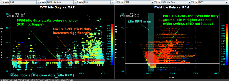
As you can see, at > ~128 MAT, the idle valve is not a happy camper. At that temp I suppose the air is significantly less dense that the valve has to open wider to maintain the RPM. If we put a feedforward mechanism to add a user defined amount of duty above a user defined base RPM, we automatically compensate for the lower air density and keep the PID happier/less involved. Proaction is better than reaction. Which hopefully leads to a stabler idle. A lot like the battery voltage correction, and the AC idle up.
Why MAT? Why not CLT? Here's why:
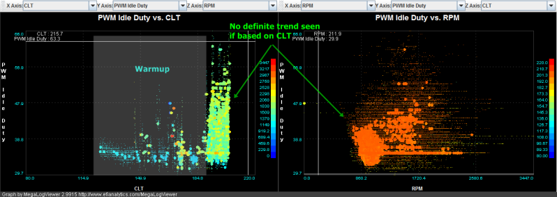
Once the engine is at operating temp, you can't see any clear change in idle valve duty based on CLT.
So yes please, to MAT based idle valve duty correction as a feedforward mechanism
Same data, presented 2 ways.
As you can see, at > ~128 MAT, the idle valve is not a happy camper. At that temp I suppose the air is significantly less dense that the valve has to open wider to maintain the RPM. If we put a feedforward mechanism to add a user defined amount of duty above a user defined base RPM, we automatically compensate for the lower air density and keep the PID happier/less involved. Proaction is better than reaction. Which hopefully leads to a stabler idle. A lot like the battery voltage correction, and the AC idle up.
Why MAT? Why not CLT? Here's why:
Once the engine is at operating temp, you can't see any clear change in idle valve duty based on CLT.
So yes please, to MAT based idle valve duty correction as a feedforward mechanism
Last edited by Greg G; 11-06-2011 at 08:21 AM.
Reply
0
0


