94 DIYPNP V1.5B Questions about AC
 07-31-2013, 11:53 PM
#1
Senior Member
Thread Starter
iTrader: (2)

Join Date: Jun 2012
Location: Texas
Posts: 1,153
Total Cats: 50
I have read brain's right up found here
Engine Management Megasquirt DIYPNP "How-To" - Step-By-Step Instructions - Miata Forumz - Mazda Miata Chat Forums
On page 3 he says how to wire for the gslender mod.
I wanted to verify that I can use the same wiring setup for my 94 as what brain stated.
I understand most of gslenders mod guide but I am confused with his wording regarding wiring.
Engine Management Megasquirt DIYPNP "How-To" - Step-By-Step Instructions - Miata Forumz - Mazda Miata Chat Forums
On page 3 he says how to wire for the gslender mod.
I wanted to verify that I can use the same wiring setup for my 94 as what brain stated.
"Instead of wiring 1Q (the a/c switch) to Input 1 IN then back OUT to 1J, simply completeing a circuit.
You'd wiring 1Q to Input 1 IN, The input 1 OUT to PE1.
Then from PAO to 1J.
Now, when the A/C switch is grounded, the MS knows, it can bump up the idle, then ground the output to 1J".
You'd wiring 1Q to Input 1 IN, The input 1 OUT to PE1.
Then from PAO to 1J.
Now, when the A/C switch is grounded, the MS knows, it can bump up the idle, then ground the output to 1J".
I understand most of gslenders mod guide but I am confused with his wording regarding wiring.

Reply
 0
0

0
08-05-2013, 10:21 AM
#3
Senior Member
Thread Starter
iTrader: (2)
Join Date: Jun 2012
Location: Texas
Posts: 1,153
Total Cats: 50
Right now it is wired 1q>input 1 in>input 1 out> 1J
If I go 1Q to Input 1 IN, The input 1 OUT to PE1.
Then from PAO to 1J.
Problem is PAO is already being used for boost control.
Attached is a picture
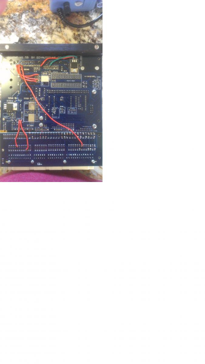
sorry for the retarded pic im out in the sticks today on an old *** computer and dial up internet (in laws)
If I go 1Q to Input 1 IN, The input 1 OUT to PE1.
Then from PAO to 1J.
Problem is PAO is already being used for boost control.
Attached is a picture
sorry for the retarded pic im out in the sticks today on an old *** computer and dial up internet (in laws)
Reply
0
0
08-05-2013, 10:55 AM
#4
Boost Czar


iTrader: (62)
Join Date: May 2005
Location: Chantilly, VA
Posts: 79,501
Total Cats: 4,079
That looks like I built it!
move boost to pt7 and do the rest as outlined.
also, you can't go directly from PA0 to 1J, it has to go through the relay circuit first, or through WLED or ALED instead of PA0.
it should end up looking like this:
move boost to pt7 and do the rest as outlined.
also, you can't go directly from PA0 to 1J, it has to go through the relay circuit first, or through WLED or ALED instead of PA0.
it should end up looking like this:
Reply
0
0
08-05-2013, 11:07 AM
#5
Senior Member
Thread Starter
iTrader: (2)
Join Date: Jun 2012
Location: Texas
Posts: 1,153
Total Cats: 50
It is one of yours. I am the third owner I believe. I will try it out and come back with results. I finally got my turbo installed this weekend and COPS. So im official.
Reply
0
0
08-05-2013, 11:51 AM
#6
Senior Member
Thread Starter
iTrader: (2)
Join Date: Jun 2012
Location: Texas
Posts: 1,153
Total Cats: 50
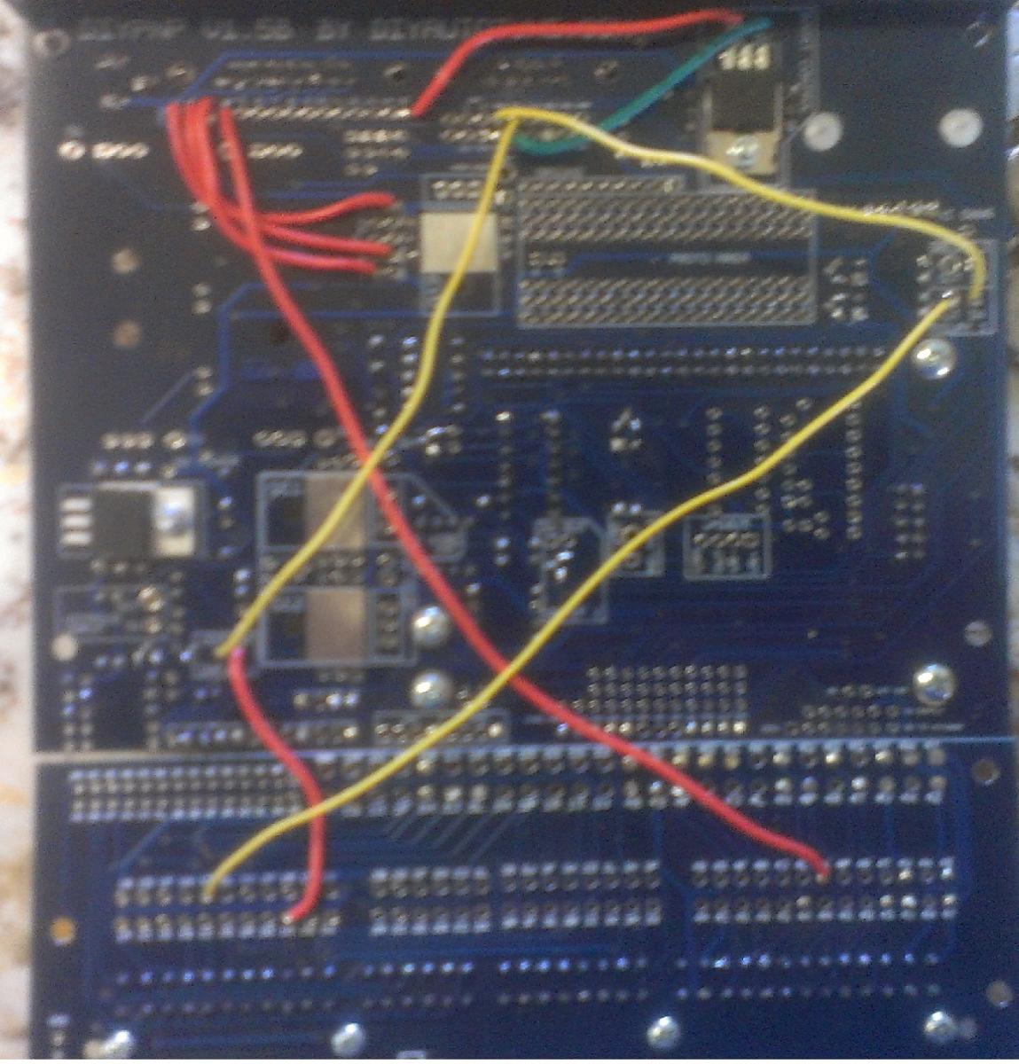
What I have so far. When you say 1j and 4s. I notice there are a lot of them so I just jumped Relay 1 out to 1j where input out was previous wired too. Im not sure if thats correct but heres another picture.
Reply
0
0
08-05-2013, 01:21 PM
#10
Boost Czar
iTrader: (62)
Join Date: May 2005
Location: Chantilly, VA
Posts: 79,501
Total Cats: 4,079
you need to make sure 1J and 4S are connected together.
1J is the a/c compressor and 4S is the a/c fan. You want to tie them together so that the MS turns on the fan with the compressor.
1J is the a/c compressor and 4S is the a/c fan. You want to tie them together so that the MS turns on the fan with the compressor.
Reply
0
0
08-05-2013, 04:25 PM
#15
Senior Member
Thread Starter
iTrader: (2)
Join Date: Jun 2012
Location: Texas
Posts: 1,153
Total Cats: 50
My compressor quit kicking on. So I think both of my relays took a crap on me. I took them out and jumped them and sure enough the fan kicked on and so did the compressor. I would normal jump to conclusions and blame it on the ms but I noticed this issue the other day when I was driving the ac fan would turn off and the temp went up and shortly after the compressor would cut off. After a while they would both kick on and go back to normal. his was before I even installed the ms. So long story short I think I just need relays.
Reply
0
0
08-08-2013, 07:15 AM
#17
Boost Czar
iTrader: (62)
Join Date: May 2005
Location: Chantilly, VA
Posts: 79,501
Total Cats: 4,079
do you have r14 installed? you need to install a 2.2K resistor in r14, and might as well pop one in the input 2 circuit and run 1V to Input 2 IN, and input 2 OUT to FLEX and use that for launch control.
Reply
0
0
08-08-2013, 08:42 AM
#18
Senior Member
Thread Starter
iTrader: (2)
Join Date: Jun 2012
Location: Texas
Posts: 1,153
Total Cats: 50
1Q > Relay IN > Relay OUT > PE1
PA0 > Input 1 IN > Input 1 Out > 1J&4S
Reply
0
0


