MS1 losing CAS signal

 06-05-2012, 03:17 PM
#22
Boost Czar


iTrader: (62)
Join Date: May 2005
Location: Chantilly, VA
Posts: 79,504
Total Cats: 4,079
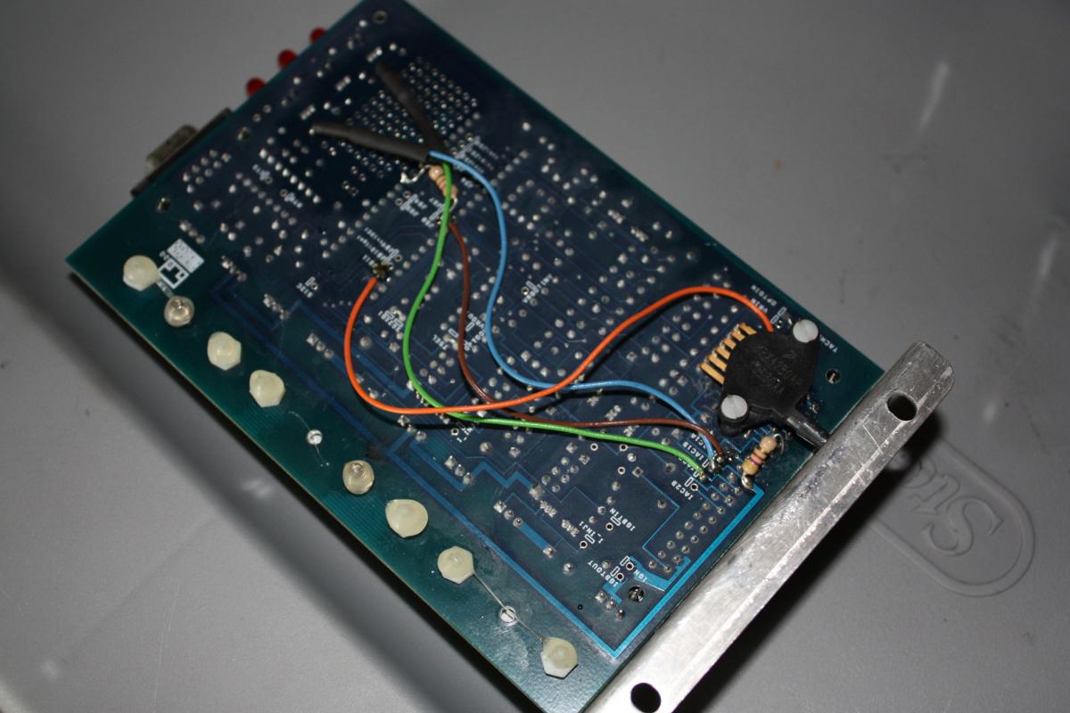
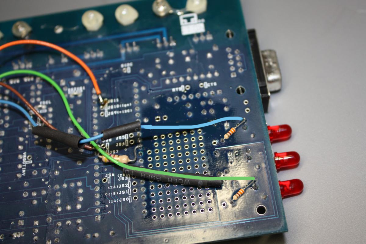
yeah, you need to move the blue and green wires and add a 100-300ohm reistors on each as such:
Green wires:
then youll use NON INVERTED for the spark output method. should see the dropouts go away, luckily your ignitor is still healthy.
you can probably go ahead and add that capacitor and remove c30 as well.
Green wires:
then youll use NON INVERTED for the spark output method. should see the dropouts go away, luckily your ignitor is still healthy.
you can probably go ahead and add that capacitor and remove c30 as well.

Reply
 0
0

0
06-05-2012, 04:04 PM
#24
Boost Czar
iTrader: (62)
Join Date: May 2005
Location: Chantilly, VA
Posts: 79,504
Total Cats: 4,079
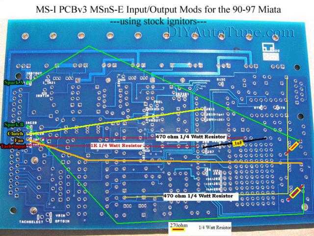
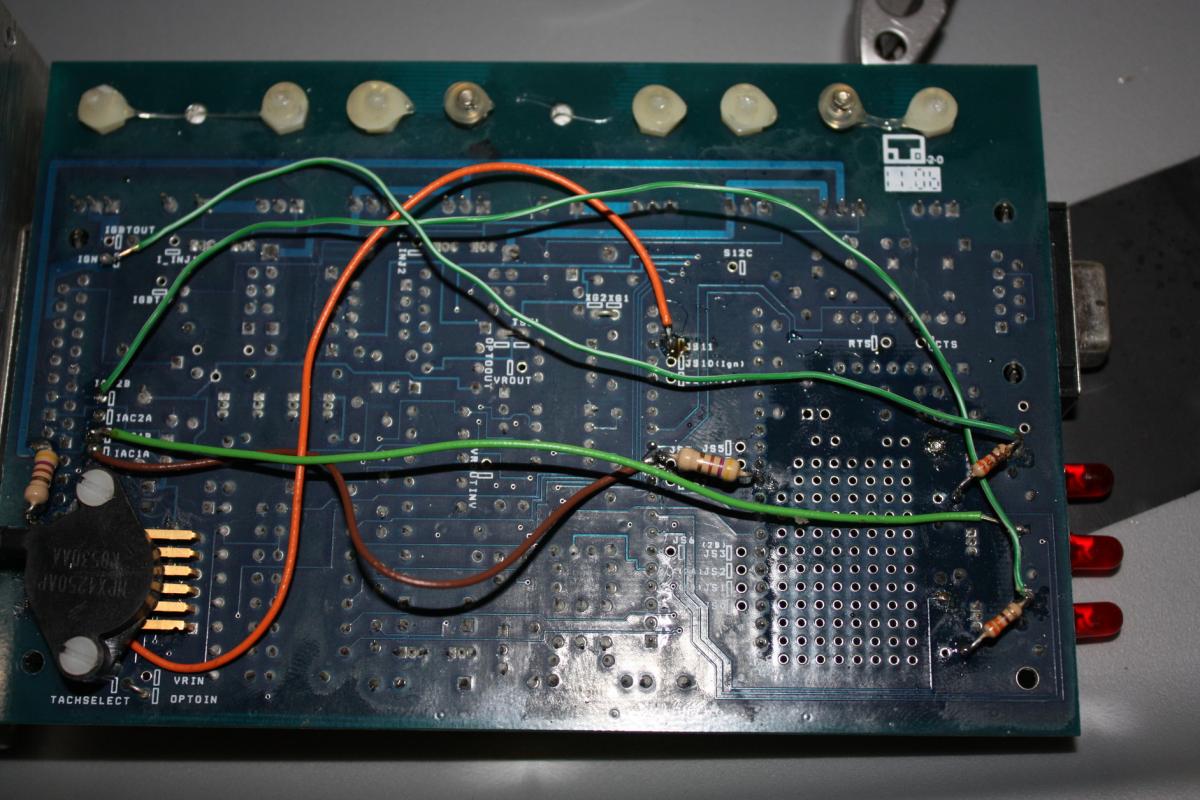
yeah but they arent going to the right spot and they aren't pullu p resistors, they are inline so far as i can tell.
look at the diagram i posted and compare how they go into the board (led side only)
look at the diagram i posted and compare how they go into the board (led side only)
Reply
0
0
 06-05-2012, 06:30 PM
#34
Boost Czar
iTrader: (62)
Join Date: May 2005
Location: Chantilly, VA
Posts: 79,504
Total Cats: 4,079
Yeah that. You'll need them. You can steal from elsewhere on the board on sec and ill figure it out
EDIT: sorry was on phone. steal from r42 and r55, they are next to each other, center of the board. put them in r26 and r29.
EDIT: sorry was on phone. steal from r42 and r55, they are next to each other, center of the board. put them in r26 and r29.
Reply
0
0
06-05-2012, 06:57 PM
#35
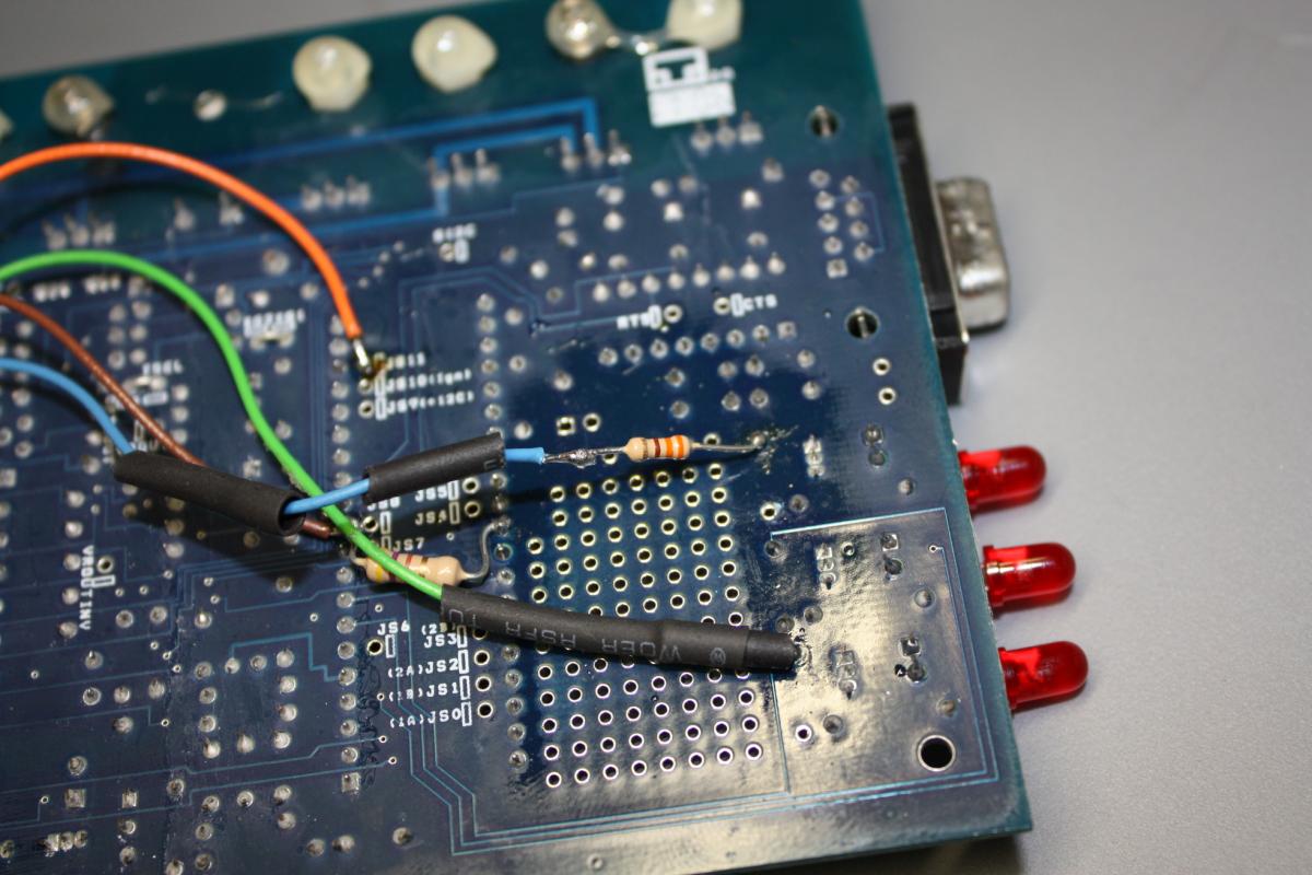
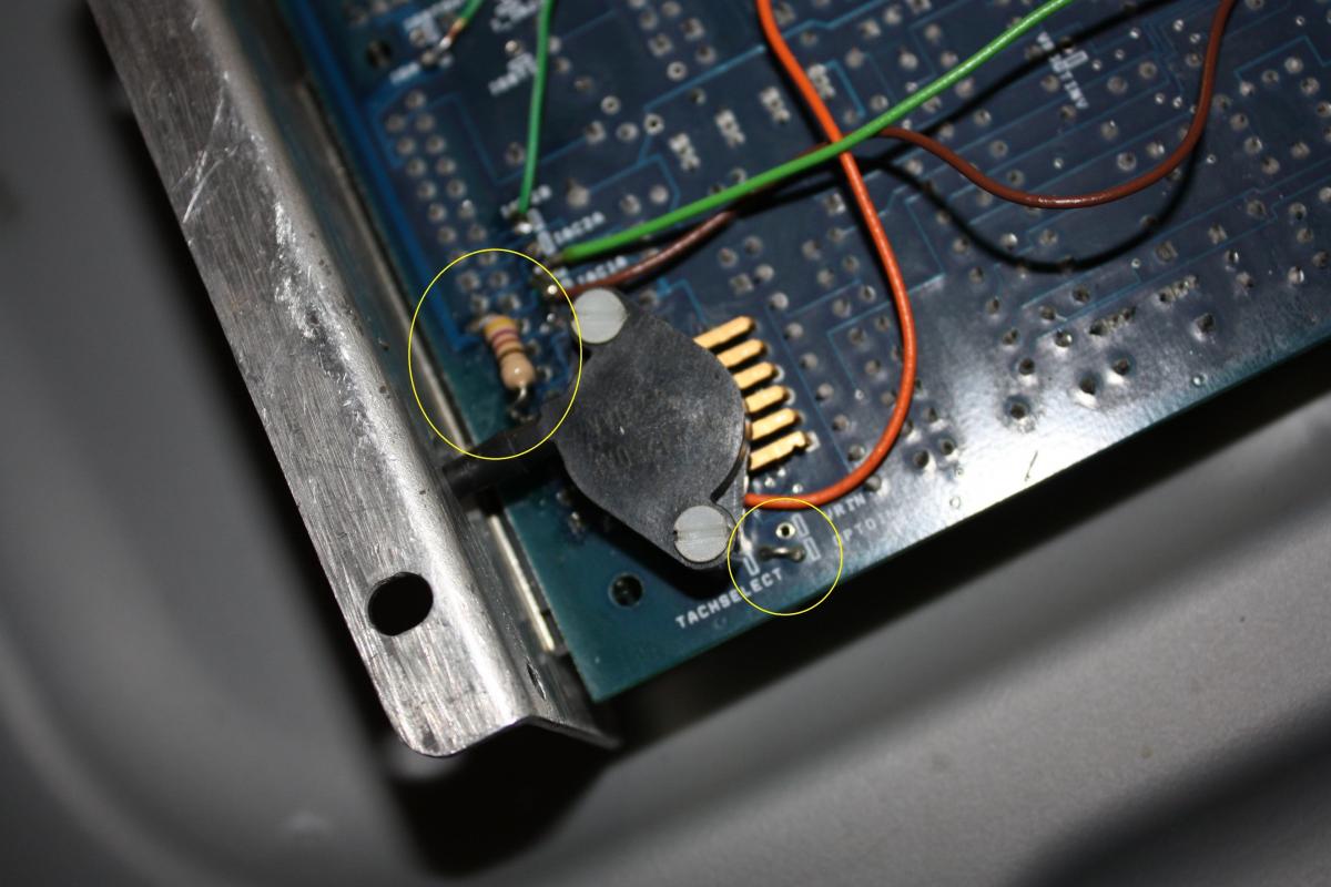
one question, i noticed on the diagram you have above, it shows there should be a 1k resistor between iac1a and js8 for tach, then 470 for iac1a to another spot
if you look at my pic, look at my brown wire for tach, its missing the 1k, and it had another resistor running from the js8 to another hole across from it, not where shown in the diagram
Reply
0
0


