Need help getting started
 09-08-2007, 08:46 PM
#1
Senior Member
Thread Starter
iTrader: (1)
Join Date: Feb 2006
Location: Detroit
Posts: 1,234
Total Cats: 0
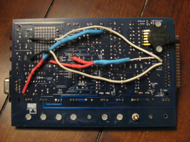
Well, I just picked up ecugrads Miatasquirt. As far as I can tell it's a version 1 with the 3.0pcb. I'm trying to figure out what I'm working with. It has switches for both fuel and spark. So I'm working with a MSnS1 ver 3.0?
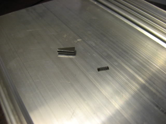
This happened during shipping. It looks like a normal switch....
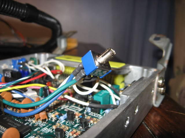
BUT these were the only parts I found in the box. It looks like the toggle switch. It had this spring inside the toggle. I don't think it's supposed to do that. I'm pretty sure it needs replacing right?
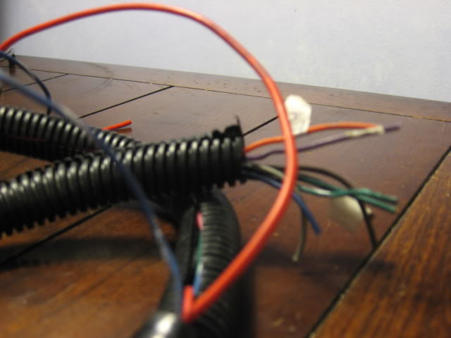
Where can I find the instructions for these extra wires, as in what part of the wiring diagram should I be looking for? 4 of them should be for the IAT and CLT but the others confuse me. Do they need to be hacked into the harness, or are they all grounds?
Lastly, I don't understand this thing very well. I've been looking for a visual tutorial on tuning, but I can't seem to find one. I've read most all the links in the stickys, but I still don't understand.
I was going to use the PNP map, but on the site they said it may not be safe for me. Is there a proven base Greddy map or one that can safely get me going?
I have tried my best to answer these questions for myself, sorry if they are already answered somewhere. I appreciate the help.
This happened during shipping. It looks like a normal switch....
BUT these were the only parts I found in the box. It looks like the toggle switch. It had this spring inside the toggle. I don't think it's supposed to do that. I'm pretty sure it needs replacing right?
Where can I find the instructions for these extra wires, as in what part of the wiring diagram should I be looking for? 4 of them should be for the IAT and CLT but the others confuse me. Do they need to be hacked into the harness, or are they all grounds?
Lastly, I don't understand this thing very well. I've been looking for a visual tutorial on tuning, but I can't seem to find one. I've read most all the links in the stickys, but I still don't understand.
I was going to use the PNP map, but on the site they said it may not be safe for me. Is there a proven base Greddy map or one that can safely get me going?
I have tried my best to answer these questions for myself, sorry if they are already answered somewhere. I appreciate the help.
Last edited by miataspeed1point6; 09-08-2007 at 09:13 PM. Reason: forgot a question

Reply
 0
0

0
09-08-2007, 09:33 PM
#2
It probably already has a map on it from his car which should be fine for yours to get it started so you can do some street tuning. I would use the spark and fuel maps from DIYautotune though.
The best resource you're going to find is http://www.megasquirt.info the megamanual is located there and you need to read it all. Or you can go to http://www.msextra.com and read the manuals under the first forum link. You really need to go through it all and walk through megatune while going through it to understand what everything in it is. It probably wouldn't hurt ot read DIYautotunes manual as well for the PNP as they might have some more "simple" insight into tuning the system.
That looks like a DPDT switch and you should be able to get one at the local radioshack, it does need to be replaced.
You do have a MSI V3.0 board and it most likely running firmware 029v.
Those extra wires appear to have flags on them, what are they, that will tell you where they need to be connected.
If you go into the settings thread, you could probably try al hounos's map without problems then ad DIYautotunes fuel/ignition maps to his .msq. Set the req fuel for you injectors though. You need to set the overboost value low to begin with to be safe while tuning though.
When you think you've read enough, you still most likely have no idea. I learn something new everyday.
Reply
0
0
09-08-2007, 11:09 PM
#4
Senior Member
Thread Starter
iTrader: (1)
Join Date: Feb 2006
Location: Detroit
Posts: 1,234
Total Cats: 0
Only 2 of the tags are readable. Orange is IAT, and the black says Ground. Looking in the megamanual under the big wiring diagram I don't see where any of those wires are. Which wire does the CLT sensor connect to?
The extra wires I have are:
Dark blue
Green with white stripe
green
grey
dark grey
blue with white stripe
red
Is there a better diagram for me to look at? I could figure it out if I had one.
Here is my plan of attack:
1: Replace broken switch and CLT and IAT sensors
2: Figure out how to wire up these loose wires and sensors
3: Load the software onto my old laptop and get to know megatune
4: Come back here when I know a bit more to figure out the maps
As for the wideband I read that the LC-1 just needs to have it's output set to the right specs. So I would wire my brown output #2 wire to the purple MS wire? I'll search for the specs.
Really I just want to install it before I learn to tune it. Doing both at the same time is hard for me (I have a spare car for a while so I might as well)
The extra wires I have are:
Dark blue
Green with white stripe
green
grey
dark grey
blue with white stripe
red
Is there a better diagram for me to look at? I could figure it out if I had one.
Here is my plan of attack:
1: Replace broken switch and CLT and IAT sensors
2: Figure out how to wire up these loose wires and sensors
3: Load the software onto my old laptop and get to know megatune
4: Come back here when I know a bit more to figure out the maps
As for the wideband I read that the LC-1 just needs to have it's output set to the right specs. So I would wire my brown output #2 wire to the purple MS wire? I'll search for the specs.
Really I just want to install it before I learn to tune it. Doing both at the same time is hard for me
(I have a spare car for a while so I might as well)
Reply
0
0
09-09-2007, 01:23 AM
#5
Senior Member
Thread Starter
iTrader: (1)
Join Date: Feb 2006
Location: Detroit
Posts: 1,234
Total Cats: 0
I noticed in the wiring diagram it calls for a heated o2 sensor. If I'm using the turbo tony downpipe with the bung in the top position does it still need to be heated? What if it's in the stock Greddy position? Should I just run my LC-1 only? I have a heated o2 to use, but I heard sensors were overheating with the tony pipe.
I'd like to iron out the small issues like this early on. Tommorow would be perfect. Thanks.
I'd like to iron out the small issues like this early on. Tommorow would be perfect. Thanks.
Reply
0
0
09-09-2007, 01:55 AM
#6
If you want you LC1 WB sensor to last long, you'll mount it further down in the pipe. Too much heat will kill it. A heatsink might be in order too. That can be just a simple square made out of aluminum.
I don't use a heatsink though personally and my WB is right before the flex near the end of my DP.
I don't use a heatsink though personally and my WB is right before the flex near the end of my DP.
Reply
0
0
09-12-2007, 11:43 PM
#8
Senior Member
Thread Starter
iTrader: (1)
Join Date: Feb 2006
Location: Detroit
Posts: 1,234
Total Cats: 0
I ordered a replacement switch from my local radio shack, should be here soon. I also fixed my LC-1. Once I get some cash I will order the CLT and AIT sensors. Last thing is to source some 460cc injectors.
I really need help with the wiring. I can't seem to find a diagram that tells me where to put those loose wires. Is there a master diagram or something I'm missing? Can someone please show me where it is? Thanks.
I really need help with the wiring. I can't seem to find a diagram that tells me where to put those loose wires. Is there a master diagram or something I'm missing? Can someone please show me where it is? Thanks.
Reply
0
0
09-12-2007, 11:48 PM
#9
Yeah, here.
http://www.madracki.com/miata/wiring.html
Then use the diagram on this one as well, go to the bottom and scroll up a bit to the color wiring diagram.
http://www.megamanual.com/ms2/V3assemble.htm
http://www.madracki.com/miata/wiring.html
Then use the diagram on this one as well, go to the bottom and scroll up a bit to the color wiring diagram.
http://www.megamanual.com/ms2/V3assemble.htm
Reply
0
0
09-13-2007, 03:47 AM
#10
Junior Member

Join Date: Mar 2006
Location: Sydney Australia
Posts: 138
Total Cats: 0
Just get yourself an ohm meter and see which wire belongs to which pin (for the ones you don't know) that way you know what each pin does from the megasquirt side (wire colours in the harness can differ) then a bit of labeling anf you're good to go
Reply
0
0
09-13-2007, 08:13 AM
#12
Boost Czar


iTrader: (62)
Join Date: May 2005
Location: Chantilly, VA
Posts: 79,501
Total Cats: 4,080
CLT should be hard wired into the OEM ECU. as you use the existing thermosensor the stock ecu does. it's a yellow wire, and i dont see it hanging there out with the rest of them.
Reply
0
0
09-13-2007, 09:23 AM
#13

ecugrad's MS was built and set up by KingofL33t, just like mine. I'm going to be digging in to mine this weekend to clean up my wiring/grounding when i do my turbo install. If you haven't figured it out by Sunday or Monday i can likely answer questions about the setup, since i would be willing to bet all my wire colors and whatnot are the same as yours.
That said, the best way to do it would likely be to just pull out a multimeter and figure out which wire is which pin on the MS side. That way there are no questions, and you can connect accordingly.
as Brain said, he CLT should actually already be connected, as KingofL33t tapped the stock ECU's signals from inside the ECU itself, if i remember correctly.
Reply
0
0
09-13-2007, 07:20 PM
#15
Senior Member
Thread Starter
iTrader: (1)
Join Date: Feb 2006
Location: Detroit
Posts: 1,234
Total Cats: 0
Now I'm working on decoding that diagram by using the pins. I have never done that before so I didn't think to do it. It makes sense now though.
I was given an upper radiator hose with the thermosensor in it. I actually don't need it? I'm still unfamiliar with things like that, and the decoder wheel. I'm still reading though. Thanks for the help guys.
Reply
0
0

Thread
Thread Starter
Forum
Replies
Last Post
JesseTheNoob
DIY Turbo Discussion
15
09-30-2015 02:44 PM


