Oochi's MS3X DIY Build
 05-11-2012, 04:47 AM
#61
Junior Member

Join Date: Mar 2011
Location: Guildford, UK
Posts: 163
Total Cats: 0
Yes to Seq' fuel, either run 4 new wires or 2 new and 2 existing on the loom. Don't forget firing order is 1,3,4,2.
Seq' spark is no until you get COPS.
As for MS3 and 3X grounds, I would like piccy's as well please
Seq' spark is no until you get COPS.
As for MS3 and 3X grounds, I would like piccy's as well please

Reply
 0
0

0
 05-11-2012, 11:12 AM
#64
Junior Member
Thread Starter

Join Date: May 2011
Location: Central Kentucky
Posts: 221
Total Cats: 1
See that's what I thought so I asked and brain said no so I got all confused, but I suppose he misread or something. Anywho, if I were to run just 2 new wires and keep the other 2 in the original loom, does it matter which wire goes to which injector?
Still in for grounding help pretty please.
Still in for grounding help pretty please.
Last edited by Oochi; 05-11-2012 at 07:48 PM.
Reply
0
0
05-13-2012, 01:25 AM
#66
Junior Member
Thread Starter
Join Date: May 2011
Location: Central Kentucky
Posts: 221
Total Cats: 1
SO I think I completed the expander harness, and on to the ms harness.....I'm confused on the grounds. The grounds are all interconnected right? So it really doesnt matter where they go as long as you have 5 grounds and the 1 sensor ground? My harness looks like this, the black and white stripe being my sensor ground I suppose but I don't really know how that wires up yet.
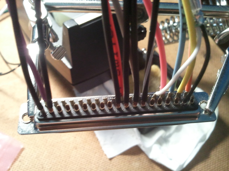
And the assembly guide says to run every single ground wire out to the engine, but I don't know why you would need to do that if they make PNP applications. Where do all of these grounds go?
And the assembly guide says to run every single ground wire out to the engine, but I don't know why you would need to do that if they make PNP applications. Where do all of these grounds go?
Reply
0
0
05-13-2012, 08:50 AM
#67
Boost Czar


iTrader: (62)
Join Date: May 2005
Location: Chantilly, VA
Posts: 79,501
Total Cats: 4,080
you should connect only the two sensor grounds to pins 1-2 (2C 2D). You didn't need to shield the cas input, it's not a shielded wire on the factory side.
main grounds from the db37 will go to pins 2A and 2B.
then ms3x grounds so all go through the main ground 2A and 2B, but preferably through there own grounds directly back to the block.
you need to follow this:
http://msextra.com/doc/ms3/hardware.html
other than the cas sheild wire, the only thing that i notice is the stripe wire on pin 7, what's that supposed to go to?
Reply
0
0
05-13-2012, 12:54 PM
#68
Junior Member
Thread Starter
Join Date: May 2011
Location: Central Kentucky
Posts: 221
Total Cats: 1
you should connect only the two sensor grounds to pins 1-2 (2C 2D). You didn't need to shield the cas input, it's not a shielded wire on the factory side.
main grounds from the db37 will go to pins 2A and 2B.
then ms3x grounds so all go through the main ground 2A and 2B, but preferably through there own grounds directly back to the block.
you need to follow this:
http://msextra.com/doc/ms3/hardware.html
other than the cas sheild wire, the only thing that i notice is the stripe wire on pin 7, what's that supposed to go to?
main grounds from the db37 will go to pins 2A and 2B.
then ms3x grounds so all go through the main ground 2A and 2B, but preferably through there own grounds directly back to the block.
you need to follow this:
http://msextra.com/doc/ms3/hardware.html
other than the cas sheild wire, the only thing that i notice is the stripe wire on pin 7, what's that supposed to go to?
So I should unshield the twisted pair, use pins 1 & 2 for the sensor grounds (2C & 2D), ground the cas at pin 8. Then connect pins 14-19 to 2A & 2B as in solder 3 of them to 2A and 3 to 2B. Then the 5 grounds from the ms3x go individually out to the block.

Reply
0
0
05-13-2012, 07:14 PM
#69
Boost Czar
iTrader: (62)
Join Date: May 2005
Location: Chantilly, VA
Posts: 79,501
Total Cats: 4,080
My personal MS3x is wired as such:
pins 1-2 - 2C & 2D
pins 7-8-9-10 - 2A & 2B (the two splice into 1 before reaching the harness)
ms3x - I have 4 of the 5 grounded (two splice into 1 before reaching harness)
so I have 2 pairs of wires on 2A&2B and 1 wire on 2C and 2D each.
If you need to run extra wires to the bay for seq spark and fuel outputs, that would be a good time to run a few grounds to main grounding point on the block (fuel rail). Then I'd connect the 4 ms3x grounds directly to that.
this is not the "ideal" way to wire it, but it works.
Reply
0
0
05-13-2012, 11:24 PM
#70
Junior Member
Thread Starter
Join Date: May 2011
Location: Central Kentucky
Posts: 221
Total Cats: 1
is there a reason you only grounded 4 and not all 5 on the ms3x? Where are they grounded?
and do you not need all the grounds on the main connector?
and do you not need all the grounds on the main connector?
Last edited by Oochi; 05-13-2012 at 11:55 PM.
Reply
0
0
05-14-2012, 01:34 AM
#71
Junior Member
Thread Starter
Join Date: May 2011
Location: Central Kentucky
Posts: 221
Total Cats: 1
A few more things I would like cleared up, using this diagram (my car is a 90)
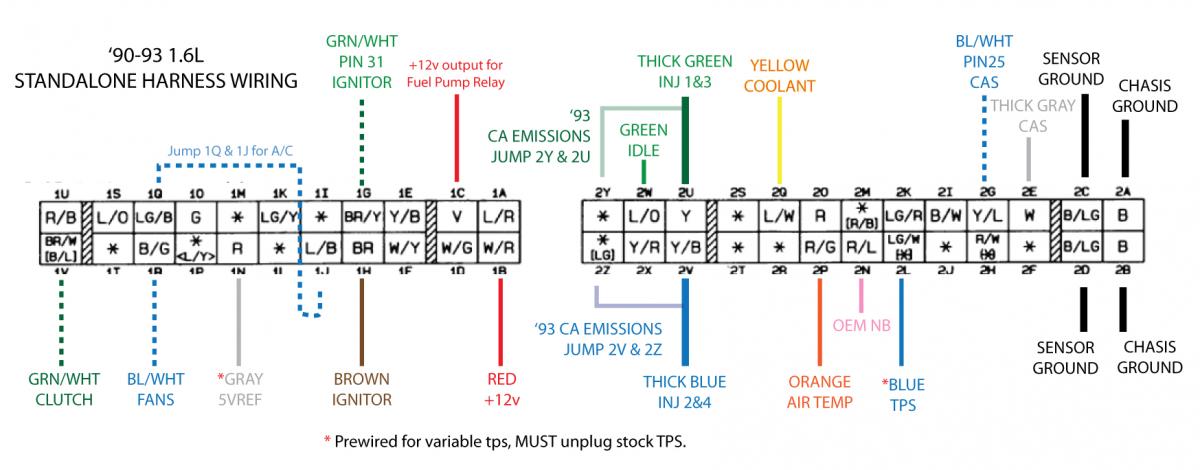
The launch control from the ms3x (pin 11) will work for the clutch switch instead of using one from the ms connector?
I may be missing it on the wiring diagrams but where does the cam input from the ms3x go to the harness?
Does the datalog input (pin30) want the datalog from the wideband? (may be a stupid question)
Does the tach output (pin 26 of ms3x) go to pin 2i?
Should I splice In the wideband signal into the stock harness at pin 2N?
Thanks in advance. I know it's a lot to ask. And sorry if obvious answers, I need sleep.
Reply
0
0
05-14-2012, 12:44 PM
#72
Boost Czar
iTrader: (62)
Join Date: May 2005
Location: Chantilly, VA
Posts: 79,501
Total Cats: 4,080
I may be missing it on the wiring diagrams but where does the cam input from the ms3x go to the harness?
Does the datalog input (pin30) want the datalog from the wideband? (may be a stupid question)
Does the tach output (pin 26 of ms3x) go to pin 2i?
Should I splice In the wideband signal into the stock harness at pin 2N?
Thanks in advance. I know it's a lot to ask. And sorry if obvious answers, I need sleep.
Reply
0
0
05-14-2012, 04:31 PM
#73
Junior Member
Thread Starter
Join Date: May 2011
Location: Central Kentucky
Posts: 221
Total Cats: 1
when it comes to this and you're way more experienced and knowledgeable than I.But thanks for the answers, though on my cas stuff; my wire is not blue/white, it's solid green and says cam input. And I used the white wire of the twisted pair to the other cas on pin 2E, but it's smaller than the other 20 gauge wires, will that be a problem? I here that others are thick grey?
Reply
0
0
05-14-2012, 06:06 PM
#74
Boost Czar
iTrader: (62)
Join Date: May 2005
Location: Chantilly, VA
Posts: 79,501
Total Cats: 4,080
that diagram was drawn back when i was building MSIs.
when you remove the shield it's the same size as the rest. that will go to pin 2E on the mainboard db37.
the cam in wire on the ms3x (pin 32) will go to 2G.
youll build the VR circuit with pull up on the mainboard. youll tune the resistors as in the manual for that mod (both 12 counter clockwise, then r56 6 turns clockwise)
youll use rising edge input on the software. couldnt be easier...its pisses me off how easy the ms3x is to build. you only have to run 2 extra wires like that above...that's it. everything else is all built in on the expander card that youll ever really need.
here use my basemap....this is setup for toyota cops right now:
Reply
0
0

 05-16-2012, 12:45 PM
#77
Junior Member
Thread Starter
Join Date: May 2011
Location: Central Kentucky
Posts: 221
Total Cats: 1
Will that be same some outcome as what brain posted without the wires? I do think I've already done that but I'll check again. I was reading through this thread: http://clubroadster.net/vb_forum/showthread.php?t=41736 and just remembered I never did the fuel pump mod on my board. slapintheface
Reply
0
0
05-16-2012, 06:09 PM
#78
Boost Czar
iTrader: (62)
Join Date: May 2005
Location: Chantilly, VA
Posts: 79,501
Total Cats: 4,080
What mod? You just install q2 q12 d5 r49 and r16 iirc.
Im sitting on the beach posting...just finish this thing man. Thers only two wires to add to the mainboard the rest is all ready on the expander. Just build the harness and be done and drive and enjoy.
Im sitting on the beach posting...just finish this thing man. Thers only two wires to add to the mainboard the rest is all ready on the expander. Just build the harness and be done and drive and enjoy.
Reply
0
0
05-18-2012, 10:47 AM
#79
Junior Member
Thread Starter
Join Date: May 2011
Location: Central Kentucky
Posts: 221
Total Cats: 1
Fuel pump mod, that thread the guy also has a 90 and was building ms3x, the guy did the fuel pump mod, but I think I just was confused because you can just jump the AFM
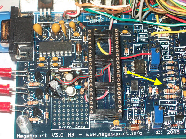
I am doing my best lol. For the VR circuit I followed westfield's directions:
Won't that be the same as the longer wire on your picture above?
jumper TACHSELECT to VRIN and jumper VROUT to TSEL
You need to add a pullup to the VR circuit. Install a 1k resistor in the left hole of R13 (= 5V). Connect the other end to the right side of R45 just below it (= VRIN)
Turn both pots (R52 and R56) about 12 turns to the fully anticlockwise position (you may feel a �click�) and then turn R56 back about 6 turns clockwise.
Reply
0
0


