Sync loss 32 question
 12-15-2016, 09:07 PM
#1
Junior Member
Thread Starter

Join Date: Jun 2015
Location: Sebring, FL
Posts: 333
Total Cats: 20
My 01 with MS3 died in my driveway today. Check engine light is on. I have a sync loss #32. I saw that means 0 cams found in 99-00. I replaced cam sensor with no change. Other than putting stock ecu in does anybody have any ideas what direction I need to look?

Reply
 0
0

0
12-15-2016, 10:29 PM
#2
Elite Member

Join Date: Mar 2007
Location: Santa Clara, CA
Posts: 5,165
Total Cats: 855
The MS3 only has two codes for the Miata, 31 and 32, and there's really no useful difference between them, so it's pretty much meaningless.
Is it consistently broken or intermittent? Have you gotten a composite log? (under 'diagnostics and high speed loggers').
--Ian
Is it consistently broken or intermittent? Have you gotten a composite log? (under 'diagnostics and high speed loggers').
--Ian
Reply
0
0
12-16-2016, 08:46 AM
#4
Junior Member

Join Date: Jan 2007
Posts: 230
Total Cats: -23
Like codrus said, the Composite Log is under Diagnostics & High Speed Loggers. You start the Composite Log, start your car and after a short while turn the car off and stop the Composite Log. Then you look to see what kind of cam and crank signal the ECU is getting and any sync loss errors. The car doesn't even need to start and run to capture this information, just turn it over with the starter motor. See http://www.msextra.com/doc/pdf/html/...rence-1.4.html
Reply
0
0
 12-16-2016, 11:27 AM
#6
Junior Member
Thread Starter
Join Date: Jun 2015
Location: Sebring, FL
Posts: 333
Total Cats: 20
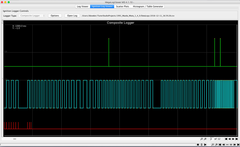
I took a diagnostics log. I don't have the paid version so I can't view it. Can anybody else read it? I really don't know what the graph is and how to interpret it anyway.
Reply
0
0
 12-17-2016, 12:22 PM
#9
Junior Member
Thread Starter
Join Date: Jun 2015
Location: Sebring, FL
Posts: 333
Total Cats: 20
I'm assuming that crank sensor is indicated by green line. Is that correct? I can see it is not consistent with blue line, which I'm guessing to be cam sensor. Can anybody confirm this to this noob? I've gone ahead and ordered a new crank sensor. The one currently in car lasted maybe 60k.
Reply
0
0
12-17-2016, 01:08 PM
#10
Elite Member
Join Date: Mar 2007
Location: Santa Clara, CA
Posts: 5,165
Total Cats: 855
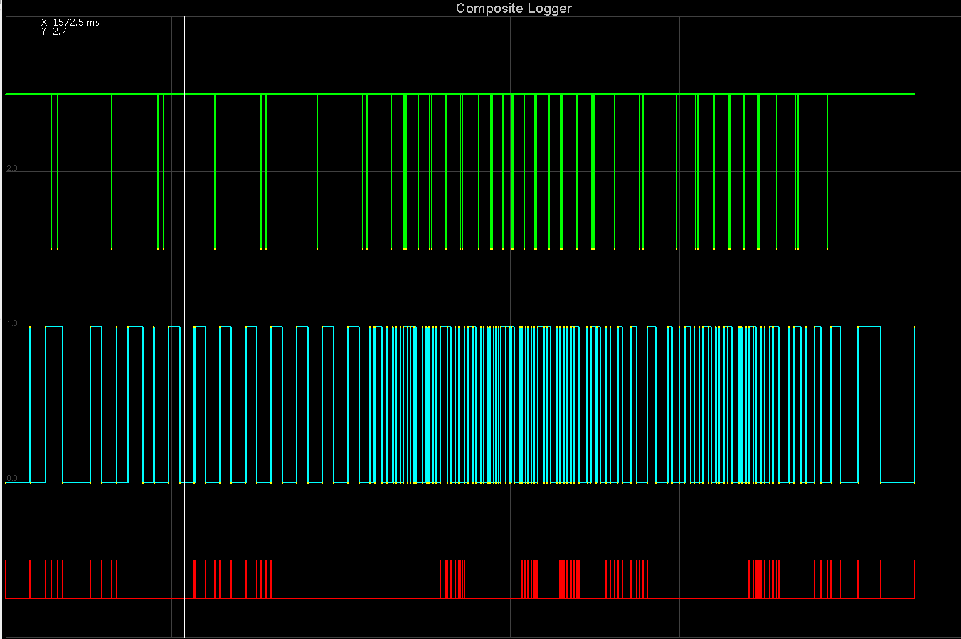
Cam is green, crank is blue.
It *should* look something like this when you zoom in: (This isn't an actual log, it's one that I generated with a simulator to demo it, but it's close).
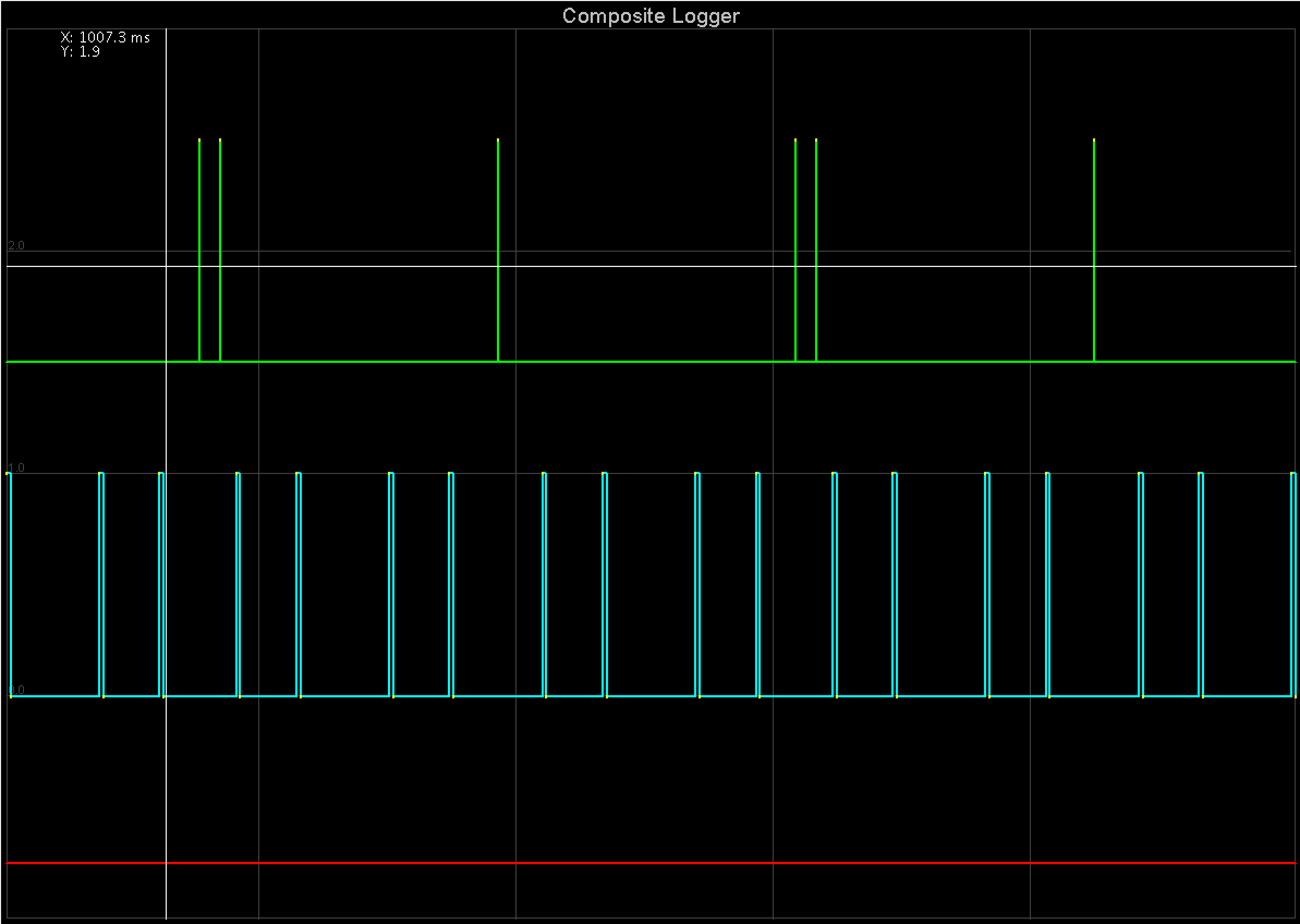
Green is cam, blue is crank. The crank has 4 teeth on it, and the cam has 3, remember that the crank turns twice as fast as the cam does. The crank's teeth are not evenly spaced, there are two slightly closer together, followed by a slightly larger gap, followed by two more, followed by another slightly larger gap. The cam teeth are set up with 2 next to each other on one side, and a single one that is 180 degrees around from them.
So when they turn, the megasquirt sees a forever-repeating cycle of the following pulses:
crank pulse - crank pulse - crank pulse - crank pulse - CAM PULSE - crank pulse - crank pulse - crank pulse - crank pulse - CAM PULSE - CAM PULSE
This takes place over 720 degrees of crank rotation (two complete turns) and 360 degrees of cam rotation (one complete turn).
In a composite log, the ECU is logging the time at which it sees three types of events, crank pulse going high, crank pulse going low, and cam pulses. Yes, for some reason it logs both edges of the crank pulse, but only one for the cam, I don't know why. The composite log viewer displays these pulses, showing you the rise/fall of the crank (and the resulting tooth width), and a single spike for the cam (no width data is available).
The sync logic in the MS3 is watching the signals from the two inputs, expecting to see the pattern above. As long as the events come in that order it knows where the engine is, because it can compute RPM by looking at the time between the events and by looking at the recent history of speed it can compute if the engine is accelerating or decelerating, and predict when the next pulse should come. If, OTOH, it gets an event that comes in the WRONG order, then it gets totally confused and declares a "sync error".
The logic for the Miata tooth decoder (there are like 30 different tooth decoders in the megasquirt code) doesn't detect every possible sync error, however. Instead what it does is to count crank pulses, and when it reaches 4, it looks for at least one cam pulse coming before the next crank pulse. That's it. It doesn't detect extra cam pulses, in fact it doesn't even look to see that it gets 2 cam pulses at the right time (comments in the code suggest it used to, but to make some VVT engines work they needed to take that out). It also doesn't detect cam pulses that come at the wrong time. Code 31 means that it didn't see a cam pulse after 4 cranks, and 32 means it didn't see a cam pulse after 8 cranks, that's all.
So, you can get code 31/32 by having a cam sensor that is bad and missing occasional pulses. You can also get it by having a crank sensor that is bad and missing occasional pulses, because what happens is that the ECU sees:
crank pulse (1) - crank pulse (2) - crank pulse (3) - <missing crank pulse> (should be 4) - cam pulse (ignored) - crank pulse (counted as 4, should be 5) - crank pulse (counted as 5, should be 6)
Since crank pulse 4 gets missed here, the ECU ignores the cam pulse between 4 and 5, mis-counts crank pulse 5 as 4, and then sync errors when it sees crank pulse 6 (which it counts as 5) without a cam pulse between what it thinks is 4 and 5.
This is what I mean why I say that the sync error reason is meaningless.
--Ian
It *should* look something like this when you zoom in: (This isn't an actual log, it's one that I generated with a simulator to demo it, but it's close).
Green is cam, blue is crank. The crank has 4 teeth on it, and the cam has 3, remember that the crank turns twice as fast as the cam does. The crank's teeth are not evenly spaced, there are two slightly closer together, followed by a slightly larger gap, followed by two more, followed by another slightly larger gap. The cam teeth are set up with 2 next to each other on one side, and a single one that is 180 degrees around from them.
So when they turn, the megasquirt sees a forever-repeating cycle of the following pulses:
crank pulse - crank pulse - crank pulse - crank pulse - CAM PULSE - crank pulse - crank pulse - crank pulse - crank pulse - CAM PULSE - CAM PULSE
This takes place over 720 degrees of crank rotation (two complete turns) and 360 degrees of cam rotation (one complete turn).
In a composite log, the ECU is logging the time at which it sees three types of events, crank pulse going high, crank pulse going low, and cam pulses. Yes, for some reason it logs both edges of the crank pulse, but only one for the cam, I don't know why. The composite log viewer displays these pulses, showing you the rise/fall of the crank (and the resulting tooth width), and a single spike for the cam (no width data is available).
The sync logic in the MS3 is watching the signals from the two inputs, expecting to see the pattern above. As long as the events come in that order it knows where the engine is, because it can compute RPM by looking at the time between the events and by looking at the recent history of speed it can compute if the engine is accelerating or decelerating, and predict when the next pulse should come. If, OTOH, it gets an event that comes in the WRONG order, then it gets totally confused and declares a "sync error".
The logic for the Miata tooth decoder (there are like 30 different tooth decoders in the megasquirt code) doesn't detect every possible sync error, however. Instead what it does is to count crank pulses, and when it reaches 4, it looks for at least one cam pulse coming before the next crank pulse. That's it. It doesn't detect extra cam pulses, in fact it doesn't even look to see that it gets 2 cam pulses at the right time (comments in the code suggest it used to, but to make some VVT engines work they needed to take that out). It also doesn't detect cam pulses that come at the wrong time. Code 31 means that it didn't see a cam pulse after 4 cranks, and 32 means it didn't see a cam pulse after 8 cranks, that's all.
So, you can get code 31/32 by having a cam sensor that is bad and missing occasional pulses. You can also get it by having a crank sensor that is bad and missing occasional pulses, because what happens is that the ECU sees:
crank pulse (1) - crank pulse (2) - crank pulse (3) - <missing crank pulse> (should be 4) - cam pulse (ignored) - crank pulse (counted as 4, should be 5) - crank pulse (counted as 5, should be 6)
Since crank pulse 4 gets missed here, the ECU ignores the cam pulse between 4 and 5, mis-counts crank pulse 5 as 4, and then sync errors when it sees crank pulse 6 (which it counts as 5) without a cam pulse between what it thinks is 4 and 5.
This is what I mean why I say that the sync error reason is meaningless.
--Ian
Reply
2
2
12-17-2016, 04:24 PM
#11
Junior Member
Thread Starter
Join Date: Jun 2015
Location: Sebring, FL
Posts: 333
Total Cats: 20
Thanks for the in depth explanation of the composite graph. I saved it in a file. It really showed me what's going on. I went as far as putting stock ecu and maf on to see if I could get a readable code. Got nothing. I ordered my crank sensor from Rock Auto, so it will take a week for me to resolve this. They were fifty bucks cheaper than the parts store so I figured I'd wait.
Reply
0
0
12-17-2016, 04:33 PM
#12
Retired Mech Design Engr
iTrader: (3)
Join Date: Jan 2013
Location: Seneca, SC
Posts: 5,009
Total Cats: 857
Ian, although I too have read about MS ignoring the single vs double cam pulse, the MS must differentiate, else it would not know if the engine is on the firing stroke of, say, 1 vs 4. An entire engine cycle is 720 degrees, or 8 crank pulses. So. I would say that a more complete view is that single or double may be ignored relative to sync or not sync, but they cannot be totally ignored for sequential injection and ignition to work.
Reply
0
0
12-17-2016, 10:08 PM
#13
Elite Member
Join Date: Mar 2007
Location: Santa Clara, CA
Posts: 5,165
Total Cats: 855
Ian, although I too have read about MS ignoring the single vs double cam pulse, the MS must differentiate, else it would not know if the engine is on the firing stroke of, say, 1 vs 4. An entire engine cycle is 720 degrees, or 8 crank pulses. So. I would say that a more complete view is that single or double may be ignored relative to sync or not sync, but they cannot be totally ignored for sequential injection and ignition to work.
--Ian
Reply
0
0
12-18-2016, 01:12 AM
#14
Retired Mech Design Engr
iTrader: (3)
Join Date: Jan 2013
Location: Seneca, SC
Posts: 5,009
Total Cats: 857
I see, sorta. Now we move into your SW world. When I was fighting sync loss, my very all-around HW / FW friend said something like that. That there were instances when I had some funny signals reported, that did not result in poor running, he was saying that the fast part of the system that the micro acted on saw the pulses correctly, but that the reporting SW that built the output waveforms for the log missed something.
Cheers
Cheers
Reply
0
0
 12-18-2016, 07:55 AM
#16
Retired Mech Design Engr
iTrader: (3)
Join Date: Jan 2013
Location: Seneca, SC
Posts: 5,009
Total Cats: 857
Sync losses at starting, in my experience, are common, and don't mean much; as you say. However, sync losses during running results in misfires to shutdowns.
If you think about it, if the MS does not know where the pistons are, you don't want spark.
If you think about it, if the MS does not know where the pistons are, you don't want spark.
Reply
0
0
 12-18-2016, 09:34 AM
#18
Senior Member

Join Date: May 2007
Location: Atlanta
Posts: 997
Total Cats: 156
In your case, sync loss is also similar to "misfire". There are "windows" where the edge of signal changes are expected to happen based upon RPM - so at 3000 RPM we know that in 1.2ms expect a signal edge. If something else causes a misfire - like the coils or injectors - and the window passes without the signal (because crank speed suddenly changed) the code throws "out of sync" and throws away its schedule of injector and spark events until sync is reestablished (2 crank revolutions minimum). During start, the windows are very large - but a VR sensor needs some speed to be picked up cleanly.
Reply
1
1
12-18-2016, 10:57 AM
#19
Retired Mech Design Engr
iTrader: (3)
Join Date: Jan 2013
Location: Seneca, SC
Posts: 5,009
Total Cats: 857
One issue I had when trying to sort out my sync issues was trying to find a picture of how the log was supposed to look. All of the old threads I found had broken picture links.
It would be nice if someone would post a good log shot.
It would be nice if someone would post a good log shot.
Reply
0
0


