When you click on links to various merchants on this site and make a purchase, this can result in this site earning a commission. Affiliate programs and affiliations include, but are not limited to, the eBay Partner Network.
Does anyone have the pinout for the connector that runs to the rear of the car. It's found along the driver side frame rail where the door wiring is. It's a white rectangular connector with a bunch of small pins and a few larger ones. I decided to gut my entire harness and start from scratch as I'm going to an ecotec and have to do most everything over anyway. Plus it will make trouble shooting stuff easier.
Man those are pricy. It's a lemons race car so I'm not running ANYTHING fancy. Every think that needs a relay will get one but everything will be on a on/off toggle switch. Brake lights are the only lights I'll be running that will work on the Oem pressure switch which is why I'm asking for the plug pin out. Fuel pump, starter, ignition, radiator fan, and wiper motor are pretty much they only things getting a relay. If I'm missing something please point it out. Gauges are running off a race capture. Might need an key on relay but that's about it. No head lights, blinkers, radio, HVAC, ect.
Here is the box I will be using.
ONLINE LED STORE 12-Slot Relay Box [6 Relays] [6 Blade Fuses] [Bosch Style Relays] [Easy Installation] [OEM Factory Look] - Fuse Relay Box for Automotive and Marine Use
Yeah I looked that over and the other wiring diagram on the service manual website but I don't see anywhere that calls out the wiring for the brake lights....
That doesn't tell me the whole story. Really I'm looking for a color guide to this plug
You won't find a diagram that shows that plug and what the wires do. You will need to trace all those wires back to where they end, label them. Then you can find in the wiring diagrams what they are for and where they go. The wiring diagrams from Mazda just don't show all the random connectors in the harnesses.
Yeah, I haven't been able to find wiring diagrams for NA's that have connectors. I found one for NB1's that have every connector with their pinout and a picture of where the connector is, it looks like it's stamped with Mazda OE marks, so it's not like a Chiltons or aftermarket diagram. I would do what Lars suggested, follow the wires to their nearest connection, then look up the wiring diagram for that wire color.
Here is what I had my harness.
Blue/Red - Fuel Pump
Yellow - Fuel Gauge
Green/White - Right Turn
Red/White - Door Switch
N/C
Red/Green - Backup lights
Green/Black - Left Turn
Green - Brake Lights
Blue/White - P. Brake
Red/Black - Running Lights
Last edited by mweber; 01-03-2019 at 07:25 AM.
Reason: Fix formatting
OP, I did something similar with our Lucky Dog car, I think just probing them to figure out what did what. Only use fuel gauge, pump, brakes, and tail lights.
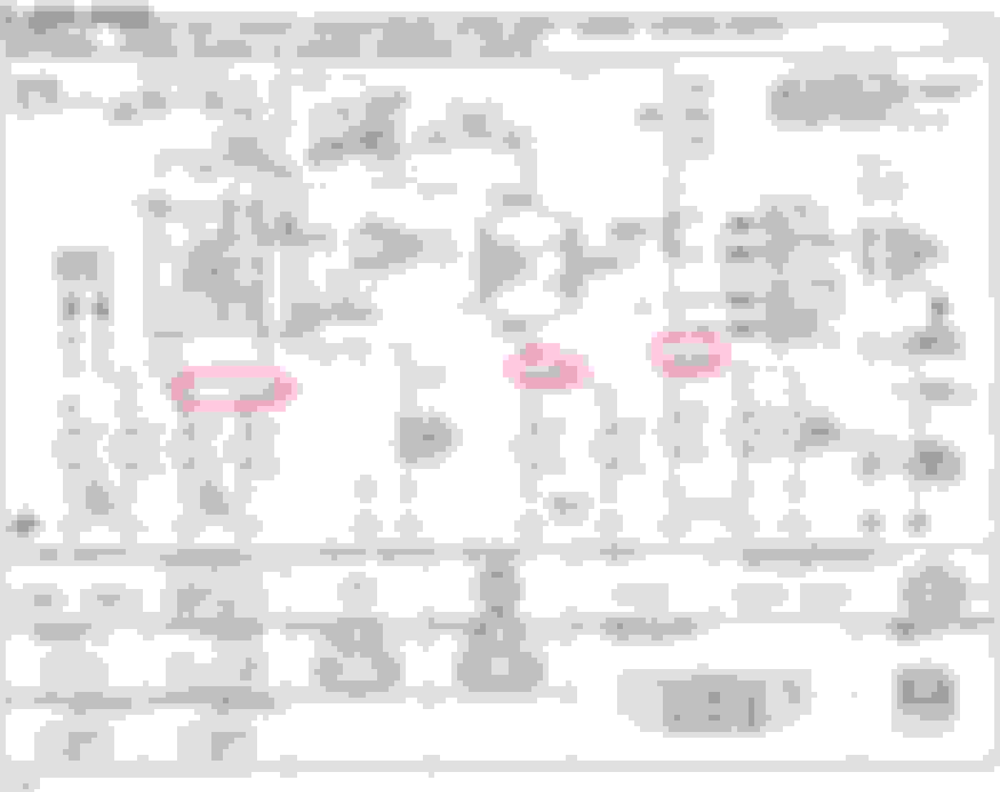
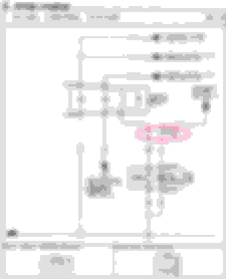
The wiring diagram is at the end. That connector is scattered across many pages. Here's how you find it:
See those calloouts labeled X-14? Each time you find one of those, that means that the wire in question passes through that connector at the point shown. More:
This is by no means a complete list, but it'll get you started.
I had him use covered fuse panels and heatshrink connectors everywhere. If memory serves correctly, relays were accessories, lights, ecu, fp, and fan. Fan is 12v triggered with the GM ecu vs ground triggered like the rest. Only rewired it a bit so the accessories came on with the kill switch. It’s worked flawlessly for a year now, including multiple victories!

 12-30-2018, 06:07 PM


 0
0