
Some Seam Weld Photos
 08-08-2011, 10:57 AM
#21
I'm Miserable!
Thread Starter

Join Date: Feb 2010
Posts: 583
Total Cats: -1
The reason for the spacing is to limit crack propagation. If you have one solid weld and a crack starts, it will almost inevitably spread through the entire weld, ruining everything you just did. By making numerous smaller welds, a crack will ruin just one weld. The "pattern" or spaced out method would be the right way to do it.
Years back I used to lay layers of composites into some beater car floors, rails and tunnels. Epoxy glue and fiberglass or kevlar, whatever was handy. You know what? It helped a ton. Even before a cage was added. I bet it would help Miatas too. It is labor intensive and there are some tricks to it, but the material costs are not bad at all.
Then there is the old structural foam strategy. You can do it yourself, and many new cars already come foamed. Besides stiffening, it helps with NVH.
An old trick from a buddy at Koni was to strip a car and then drive it hard with that white correctype paint on suspect areas. The stuff they used to use back in the typewriter days. It is opaque but very weak paint and it dries instantly. After your drive you examine and photograph whereever the paint cracked. That is where your unibody is flexing excessively. Fix those areas and your car will wind up faster.
The goal of these structural mods is to make the car stiffer both in bending and torsion. This helps both ride and handling and makes the car easier and more predicable to control.

Reply
 0
0

0
08-08-2011, 11:30 AM
#22
I'm Miserable!
Thread Starter
Join Date: Feb 2010
Posts: 583
Total Cats: -1
Here is a picture from a local car I'm seam welding. Seats out, carpet rolled back. Ugh, look at this crummy brace. It is not even achieving stock benefits. This is the driver's side brace that lives behind the lower seat belt mount on the rocker. It will be seam welded of course. I may first cut it off and start again so that it fits flush. Or leave it and tap the gaps flush. This is a very important brace and as you can see it cannot be doing much since it is barely attached to the rocker. Hmm…looking it over again I see a couple more "fails" I should have added. For shame Mazda!!
See, part of doing things like seam welding, corner balancing, and engine blueprinting involves more completely achieving the design intention. In the real world things don't always turn out quite so perfect in cheap car mass production.
See, part of doing things like seam welding, corner balancing, and engine blueprinting involves more completely achieving the design intention. In the real world things don't always turn out quite so perfect in cheap car mass production.
Last edited by sjmarcy; 08-08-2011 at 11:49 AM.
Reply
0
0
08-08-2011, 05:01 PM
#23
I'm Miserable!
Thread Starter
Join Date: Feb 2010
Posts: 583
Total Cats: -1
Here is a setup weld, getting the settings close on a HF welder using Lincoln wire. Not that bad for the price really. This is just wire brushed for like 5 seconds after the weld cooled. It's a serviceable unit if your budget is tight. Just use better wire than they provide is my tip. You can see the factory spot welds to the left and right of it.
Reply
0
0
08-09-2011, 04:05 PM
#24
I'm Miserable!
Thread Starter
Join Date: Feb 2010
Posts: 583
Total Cats: -1
Okay I have the car I just interior seam welded for just a bit longer. So here is an anecdote.
It is an older high mileage Miata. That has trouble with opening a door if the car is jacked at a corner. Jack it and then the doors balk at opening or closing.
It also showed flexy flier signs entering NC driveways. In this area many of the streets have these combination curb and water drainage feature. So they are like a wide but steep curb. On lowered cars you MUST enter them at a steep diagonal. Well this twists the car torsionally along the F/R axis. This older Miata would flash it's interior light when entering or leaving my driveway.
Now the light stays out!
The automatic switches for the doors live at the lower rearmost door jams. That way they activate when you open a door. Well this car would twist enough that the switch would close when you do a driveway entrance or exit. Now that the unibody is stiffer, the interior light no longer flickers. Definitely the car is more solid.
I will see if the guy wants to do those frog arms or maybe I will make him a set. That should further help the car.
Reply
0
0
08-12-2011, 01:33 PM
#25
I'm Miserable!
Thread Starter
Join Date: Feb 2010
Posts: 583
Total Cats: -1
Here are some rocker cross section photos I came across. The one with extra sheet metal is from an NB, the basic one is an NA. Hmm I didn't know this! It seems like there are some extra zones that could benefit from seam welding on an NB, the outboard layers to one another. I wonder if the NA cars varied over the years. I think that Miatas got more unibody gussets over the years. FWIW my 97 has reinforcement at the rocker behind the seat and at the corners of the foot wells under the dash at the tranny tunnel and at the outboard kick panel.
Last edited by sjmarcy; 08-12-2011 at 01:50 PM.
Reply
0
0
08-12-2011, 05:31 PM
#26

Here are some rocker cross section photos I came across. The one with extra sheet metal is from an NB, the basic one is an NA. Hmm I didn't know this! It seems like there are some extra zones that could benefit from seam welding on an NB, the outboard layers to one another. I wonder if the NA cars varied over the years. I think that Miatas got more unibody gussets over the years. FWIW my 97 has reinforcement at the rocker behind the seat and at the corners of the foot wells under the dash at the tranny tunnel and at the outboard kick panel.
Reply
0
0
08-12-2011, 11:13 PM
#27
I'm Miserable!
Thread Starter
Join Date: Feb 2010
Posts: 583
Total Cats: -1
On cages, many folks are not interested in them. In my case I can't even seam weld my car, never mind caging it as it is not allowed in my autocross class. However I do it on other cars and just seam welded part of a local street Miata that was getting to be too much of a flexible flyer. I had a chance to look it over pretty carefully while it was apart. The guy wants some more things done so I will further firm up his car in a month or so. You can stiffen up the unibody quite a bit for low cost and without giving up any space.
Reply
0
0
08-13-2011, 02:29 PM
#28
Elite Member

Join Date: Jul 2005
Posts: 6,420
Total Cats: 84
+1 I wouldn't want a cage in my street miata. Additionally, I rode in a caged spec miata that somehow had more chassis shimmy than mine.
sjmarcy,
Do you think the door sills will have a significant effect? (I've got door bars already-huge effect) It's probably the easiest to prep and do:
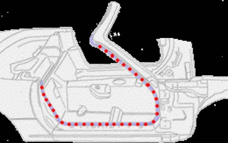
I have the opportunity to get this done for free, but I don't want to burn through a favor if it won't help much.
sjmarcy,
Do you think the door sills will have a significant effect? (I've got door bars already-huge effect) It's probably the easiest to prep and do:
I have the opportunity to get this done for free, but I don't want to burn through a favor if it won't help much.
Reply
0
0
08-13-2011, 02:44 PM
#29

I did pretty much those red dots in the pic you posted.
+1 I wouldn't want a cage in my street miata. Additionally, I rode in a caged spec miata that somehow had more chassis shimmy than mine.
sjmarcy,
Do you think the door sills will have a significant effect? (I've got door bars already-huge effect) It's probably the easiest to prep and do:
I have the opportunity to get this done for free, but I don't want to burn through a favor if it won't help much.
sjmarcy,
Do you think the door sills will have a significant effect? (I've got door bars already-huge effect) It's probably the easiest to prep and do:
I have the opportunity to get this done for free, but I don't want to burn through a favor if it won't help much.
Reply
0
0
08-13-2011, 07:14 PM
#30
I'm Miserable!
Thread Starter
Join Date: Feb 2010
Posts: 583
Total Cats: -1
+1 I wouldn't want a cage in my street miata. Additionally, I rode in a caged spec miata that somehow had more chassis shimmy than mine.
sjmarcy,
Do you think the door sills will have a significant effect? (I've got door bars already-huge effect) It's probably the easiest to prep and do:
I have the opportunity to get this done for free, but I don't want to burn through a favor if it won't help much.
sjmarcy,
Do you think the door sills will have a significant effect? (I've got door bars already-huge effect) It's probably the easiest to prep and do:
I have the opportunity to get this done for free, but I don't want to burn through a favor if it won't help much.
A) Door sill seam like in the photo…suggest doing those in a stitch fashion rather than one continuous weld for various reasons. This is the zone that the pull-off weather stripping and scuff plates cover. I would not be too worried about the front seat mount brace but while you're there it can be done.
B) All three of the braces Mazda added compared to the earlier cars. The one joining the rocker and rear panel behind the seat. It is near the rocker mount for the seat belts and I included a picture of one in this thread. In that case that brace was not even active as delivered by Mazda since some of the factory welds were not performed at all. I guess the guy had seen too many pictures of Hustler's Mom, so his vision was burnt out for a few days.
The other two braces live above where your feet go in the footwells. One connects the footwell and the other side of the panel Frog arms reinforce. The other connects the footwell panel and the tranny tunnel.
Below is the outboard brace..center of picture…not the extra metal you see added, that was for a wheel well revision on a racecar. The inboard one is very similar and can be seen in the Honda motor swap thread pics from last week. Mazda put those there for a reason.
C) Finally…the upper structure that is covered by the front fenders. And the area below it and behind the wheelwell. Again, the area covered by Frog Arms.
I am not too worried about the underhood welds as that structure is pretty beefy compared to most non-convertibles. Besides, to do those well it would be easiest with the motor yanked. Especially since there is a lot of glue and seam sealer there, making prep extra important.
Note that later RX8s had their front subframes filled with two part structural foam to increase stiffness. That might help Miatas too if you are not rules limited.
Those are my present thoughts on low cost partial seam welding that is fairly accessible. I'm sure that this will change a bit after I do a few more cars and try some things out.
With your seats and plastic trim out along with carpeting rolled back access is decent. Fenders are not hard to remove either. If you show up at your friends with one seat and no fenders this can all be done pretty quickly. The areas to be welded need to be prepped. Alternate where the welds are done to control local heat. Have the car on level ground. A welder's blanket should be adequate for most of your car protection needs.
Watch out for fires…the carpeting, under-carpet insulation and those white plastic clips for the door opening zone of the carpet burn easily too.
Last edited by sjmarcy; 08-13-2011 at 07:58 PM.
Reply
0
0
08-18-2011, 02:33 AM
#33
Elite Member
Join Date: Jul 2005
Posts: 6,420
Total Cats: 84
So I had a friend do the door openings. Grinding took more time than the actual welding. He's a race fabricator, and suggested seam welding with about 30% coverage, e.g. 1" welds with 2" gaps. I ground the seams flat and marked where he was to weld, with a sharpie. I tried to more or less hit the seams between the existing factory spot welds, and then put a bit more coverage in the corners where the factory had extra layers of sheet metal (gussets) and extra spot welds. He suggested not going all the way to the top of the windshield but only to about the top of the dash. In the tight areas where the grinder wouldn't fit, I used his mini air-powered belt sander. Very cool tool. We used a sheet of aluminum to insert behind the seams to prevent damaging interior bits.
Ran out of time to clean, repaint, and reinstall interior bits.
Result:
Butt-o-meter says there was a noticeable improvement in the stiffness. The way I noticed it, was there was less shimmy in relation to the "single pulses" from tire impacts. So the tire's impacts seem to come through "clearer".
The accelerometer data of the drive to and from the shop shows that the shimmy often appears as a (musical) "chord" of 3 or 4 "notes" which are closely spaced. When there's a doublet or a triplet, before the seam welding the lowest frequency was 16.2-16.3 Hz. Now it's at 16.7 Hz. This means an increase in stiffness.
Unfortunately I took a different route going to and coming from the shop, so the roads were different, so it's hard to say if the amplitude is smaller. I will try and get a datalog on the speed bumps I did STB testing on.
So in decreasing order of effect:
- door bars
- butterfly
- shock tower bar
- door opening seam welding
I'm reasonably happy with the results, for the effort.
Reply
0
0
08-18-2011, 11:14 AM
#34
I'm Miserable!
Thread Starter
Join Date: Feb 2010
Posts: 583
Total Cats: -1
So I had a friend do the door openings. Grinding took more time than the actual welding. He's a race fabricator, and suggested seam welding with about 30% coverage, e.g. 1" welds with 2" gaps. I ground the seams flat and marked where he was to weld, with a sharpie. I tried to more or less hit the seams between the existing factory spot welds, and then put a bit more coverage in the corners where the factory had extra layers of sheet metal (gussets) and extra spot welds. He suggested not going all the way to the top of the windshield but only to about the top of the dash. In the tight areas where the grinder wouldn't fit, I used his mini air-powered belt sander. Very cool tool. We used a sheet of aluminum to insert behind the seams to prevent damaging interior bits.
Ran out of time to clean, repaint, and reinstall interior bits.
Result:
Butt-o-meter says there was a noticeable improvement in the stiffness. The way I noticed it, was there was less shimmy in relation to the "single pulses" from tire impacts. So the tire's impacts seem to come through "clearer".
The accelerometer data of the drive to and from the shop shows that the shimmy often appears as a (musical) "chord" of 3 or 4 "notes" which are closely spaced. When there's a doublet or a triplet, before the seam welding the lowest frequency was 16.2-16.3 Hz. Now it's at 16.7 Hz. This means an increase in stiffness.
Unfortunately I took a different route going to and coming from the shop, so the roads were different, so it's hard to say if the amplitude is smaller. I will try and get a datalog on the speed bumps I did STB testing on.
So in decreasing order of effect:
- door bars
- butterfly
- shock tower bar
- door opening seam welding
I'm reasonably happy with the results, for the effort.
Ran out of time to clean, repaint, and reinstall interior bits.
Result:
Butt-o-meter says there was a noticeable improvement in the stiffness. The way I noticed it, was there was less shimmy in relation to the "single pulses" from tire impacts. So the tire's impacts seem to come through "clearer".
The accelerometer data of the drive to and from the shop shows that the shimmy often appears as a (musical) "chord" of 3 or 4 "notes" which are closely spaced. When there's a doublet or a triplet, before the seam welding the lowest frequency was 16.2-16.3 Hz. Now it's at 16.7 Hz. This means an increase in stiffness.
Unfortunately I took a different route going to and coming from the shop, so the roads were different, so it's hard to say if the amplitude is smaller. I will try and get a datalog on the speed bumps I did STB testing on.
So in decreasing order of effect:
- door bars
- butterfly
- shock tower bar
- door opening seam welding
I'm reasonably happy with the results, for the effort.
I wish I had measured flex on the beater Miata I just door opening and fender seam welded. Its doors would not work properly if you jacked it at the front spot on the pinch weld. But now it works fine and does not creak nearly as much over rough roads. Are you saying that a front shock tower braces helps torsional rigidity more than seam welding the weak center portion of a Miata? Or is it more the damping post speed bump? I think I understand your point but request that you clarify it a bit.
The earlier non-US Elises had stiffer frames as their sills were higher. This made ingress/egress too difficult for the American market so they were cut down quite a bit to help out there. About 1 1/2 inches IIRC. So in effect the version for the "fat" Americans had door bars removed more or less.
For handling…what you want is high torsional rigidity along the longitudinal axis. You can measure that if you apply a twist to the car via weight or by jacking a corner and then measuring reference points.
Another method which is pretty simple involves tape. Tape a big "X" across the car from top of windshield frame to the opposite side of the car roll bar top or trunk lid zone. And do it the other way too so that you form an X. Do this on level ground so there is no flex, slight tension on the tape to avoid droop.
Now jack the car in various places. See the tape droop or break? The droop could be measured before/after a change. Less droop = more torsional rigidity. They used to do this in the 1960s when creating convertibles. I mean all they had were slide rules. The moon mission used the computer later utilized by Pong arcade games once they greatly enhanced it haha.
Another roadster design concept is used on the Honda S2000. In that instance they use an X concept before and after a central backbone. On that car, most of the strength comes from the tranny tunnel region. So the rocker/sill region is less important. They use a massive tunnel with more vertical sides. Loads are fed into it via unibody load paths from wheel corner to tunnel, diagonally.
Last edited by sjmarcy; 08-18-2011 at 11:49 AM.
Reply
0
0
08-18-2011, 12:04 PM
#35
Elite Member
Join Date: Jul 2005
Posts: 6,420
Total Cats: 84
The STB had a significant effect subjectively. In my accelerometer thread I hypothesized that while it did not increase the torsional rigidity (no increase in resonant frequency), the engine bay (which the STB should stiffen), vibrates less (and at a higher frequency), and thus the main torsional mode isn't sympathetically excited as often.
Reply
0
0
08-18-2011, 12:36 PM
#36
I'm Miserable!
Thread Starter
Join Date: Feb 2010
Posts: 583
Total Cats: -1
The STB had a significant effect subjectively. In my accelerometer thread I hypothesized that while it did not increase the torsional rigidity (no increase in resonant frequency), the engine bay (which the STB should stiffen), vibrates less (and at a higher frequency), and thus the main torsional mode isn't sympathetically excited as often.
I think the main thing for handling is the torque needed to twist the chassis along the F/R axis. If something damps vibes that is a good thing too, but won't do much for at-the-limit cornering if torsional rigidity is not changed much.
I came across some torsional rigidity figures for Miatas. Bear in mind that the required amount will change with car weight. And track width. A two ton car will need around twice that of a Miata. So…the heavier/later Miatas are stiffer, yes, but the extra mass offsets the benefit a bit. To me an NA has a vintage toy-car sort of nature…jump into a decent NB and they have more of a "car" feel. Part of that is the more solid and refined nature of the structure. Or just jump into a Porsche to feel that solid chassis characteristic. The Elise is around 10,000 IIRC [check units] but note that it is lite and has front wheel weights in the 300s - they feel subjectively solid and rigid.
For Mazdas, the RX8 has one of the more torsionally rigid chassis around, especially after they foam filled the front subframe. If rules issues allow this option, it might help Miatas too. RX8s handle wonderfully and their chassis has around double the torsional stiffness of the RX7.
Early Miatas ?,??? [Less]
(97-99) = 5,130
(99-01) = 6,412 [17 Hz IIRC was claimed?]
(01+ NBs) = ?,??? [Stiffer Rockers: more metal added]
(05-06) = 9,426 ftlb per degree of twist
(Latest NCs) ?,??? [more]
Last edited by sjmarcy; 08-18-2011 at 01:44 PM.
Reply
0
0
08-18-2011, 07:39 PM
#37
Elite Member
Join Date: Jul 2005
Posts: 6,420
Total Cats: 84
Speed bump test. Before (top), After (below). I hit the speedbumps faster this time around, yet the worst peak vibrations (red intensity) is less intense. Also if I look at the center of the worst red spot, the new data shows about 0.2 Hz higher frequency.
I'm pretty convinced it helped, but again, not as much as the STB (based on data) and not as much as the door bars or butterfly (butt-o-meter)
In a fit of industriousness, I may get a round tuit and install my Frog Arms.
Reply
0
0
08-18-2011, 11:48 PM
#39
I'm Miserable!
Thread Starter
Join Date: Feb 2010
Posts: 583
Total Cats: -1
Sort of, if I try to be charitable. ;-)
The X is too small. And does not connect to the front and rear of the unibody as well as it could. But that would take more work and expense than most can justify.
I'd be careful about placing too much credence to the spectrographs. It might make sense to cross check things using actual rigidity tests.
For one thing I'd like to look into how a shock tower brace connecting each side to one another in a strong zone is so clearly superior to seam welding a weak area of the unibody. Can you jack the car and measure twist in some manner, or try the simple tape test?
I have not seen test data on this, but it is claimed that the hard top is mostly an aid to NVH as in dampening things down more quickly and less so a rigidity mod although it does help there too.
Below is an image showing the primary structure for an S2000 marked in yellow. See the diagonals (part of the X) tying into the special backbone zone? If Honda did not send diagonal structure right to each corner of the car and thence to a designed backbone, the car would not be as torsionally rigid. I'm sure you've experienced S2000s, so you know they are quite solid. Of course Honda had quite a bit more money to spend since they started out at 35k.
Reply
0
0
08-19-2011, 03:26 AM
#40
Elite Member
Join Date: Jul 2005
Posts: 6,420
Total Cats: 84
Why would an X be more torsionally rigid than a box?
The spectrograph measures vibration, which is my primary concern. My goal is more of ride quality. The shimmy/vibration cheapens the car's feel. Not stiffness directly, nor handling - I don't run a track biased super stiff suspension. My miata is a street car / canyon carver.
The spectrograph measures vibration, which is my primary concern. My goal is more of ride quality. The shimmy/vibration cheapens the car's feel. Not stiffness directly, nor handling - I don't run a track biased super stiff suspension. My miata is a street car / canyon carver.
Reply
1
1


