
My VVT setup


Thread Starter
Elite Member
Joined: Jul 2005
Posts: 6,420
Total Cats: 84
See attached.
Left is the setup, right is an example datalog.
Notes:
- My particular AEM box (30-1040 for 95 Hondas) doesn't have the VVC#1 output available, so I used VVC #2. A particular quirk of this is that for VVC#2 to work, VVC#1 has to be enabled! The actual output for the solenoid is the "PWM #10" output which IIRC is actually injector #10 IIRC. "VVC invert" needs to be checked because the injector output is a pulldown, and when it is logic low, the solenoid receives power. PWM 9/10 period sets the PWM frequency. In this case it's about 100 Hz.
- this is for the factory 4-tooth crank trigger wheel. The setup will change with a higher resolution wheel. (cam range, vvc start).
- The units for advance is actually retard. IOW lower number is more advance. And, a quirk of the AEM with the use of a low-tooth-wheel is that the displayed advance units can't go from 0 to 47* (the real crank degrees range of the miata VVT), and not even from 0 to 23.5* (which is cam degrees). I arbitrarily set it to 0 to 20. 0 is full advance, and 20 is full retard. So '10' really means 24* advance (crank degrees). The multiplier that sets this range is "cam range".
- I set it up so that when I want full retard, the target is '25', which forces the solenoid to 0 duty cycle, given the duty table entries (lower left 2D table).
- I have full retard at very low RPM, and near full retard at redline. In between there's advance. Full advance is like from 2400 to 4800 RPM. Advance curve vs RPM does not change when MAP is >= 100 kPa. When MAP is <= 50 kPa I have full retard, and it blends to the advance curve at 100 kPa (so 75 kPa has in between).
- the way the miata vvt works, the solenoid holds the current cam phase when the duty cycle is 32%. When the duty cycle is greater than this, the cam continuously advances, when it is less, the cam continuously retards. So if you want more advance than where you are now, you have to use >32% duty cycle, then when you hit the target advance, bring it back to 32% duty.
- The "hold" duty cycle for the solenoid is 32%. This is with an SB340 diode across it (cathode or stripe connected to 12V. This is important.) Thus the duty table is set to 32% all throughout until target is '25' which will make it go to 0 duty. If you look at the datalog, when target goes to '25' (5 more than full retard which is 20), solenoid duty goes to 0.
- the error table is what changes the duty cycle quickly when there is an error.
- In the PI section only 'I' has an entry because the P is redundant, the error table is effectively a nonlinear P.
- The I is clipped at limits of -3% and +8%. This is the maximum it's allowed to change the duty cycle. The -3 especially, prevents the classic "integrator windup" problem in PID control systems. The +8% is enough to allow proper VVT operation in case the system voltage drops due to alternator failure.
- the gain of the error table (which is like P) and of I, are both experimentally optimized for best (fastest) performance with minimal overshoot and ringing. Oil temperature doesn't seem to affect performance much.
- The datalog shows that the cam angle measurement is noisy. When RPM is changing rapidly it is spikey. It doesn't seem to noticeably affect driveability.
- For your car you will have to adjust "cam start" until sensed value at full retard (solenoid disconnected) is at '20' or whatever it should be.
Last edited by JasonC SBB; Jun 20, 2010 at 07:12 PM.
Reply
 0
0

0


Thread Starter
Elite Member
Joined: Jul 2005
Posts: 6,420
Total Cats: 84
Closest thing to duty vs. error table is just the P value. In my case the equivalent P would be the slope around the 0 point, which is 15% divided by '5*' = 3. That is, 3% duty cycle change per 'degree'. Because 'degree' in this table is actually 2.4* crank degrees, that works out to only be 1.25% per crank degree of error.
What the duty vs. error table allows me to do, vs. a simple P value, is to clip the max duty change to 20%. And, in the AEM software, the P and the I total outputs are clipped together ("VVC FB max and FM min" is in the same set as 'P' and 'I' values). I want to clip the I closely to minimize windup, but the duty vs. error table needs to be clipped at a much higher value.
I also did it this so that the cam phase change velocity wouldn't be super fast due to the old worry that the simple RPM switch could pound valves (which it turns out that it looks like the real issue is that the VVT intake cam has a destructive resonance >7500 RPM).
My duty vs. target table is set mostly flat at 32%. In the Adap software, this is like setting actuator default % at 32. In my case I make it go to zero when my target is more retarded than max retard so that the valve will "rest".
Unfortunately what the Adap doesn't have is a means of clipping the max contribution of 'I' (to minimize windup), separately from the max contribution of P or duty vs. error.
The best you can do is to *never have a target = max retard* - i.e. set max retard to 1* or 2* from max retard, so that the target is always "within reach" and the I output never "winds up". (i.e. if the target is 0 (full retard), but the mechanicals only maxes out at 1* advance) Windup is when the target is out of reach, and the 'I' output ramps and pegs all the way to the end. Then when the target is suddenly within reach, the 'I' output needs to ramp all the way back (takes time) before the system finally produces a duty cycle that will make the cam phase begin to respond.
Clear as mud?
Reply
0
0


Junior Member
Joined: Jul 2014
Posts: 71
Total Cats: -42
From: North Carolina
Jason,
Im going to give a little about myself as not to make you feel as if your wasting your time with any responses. I am new to this forum but not new to miatas, engines or AEM EMS software. Ive been road racing with NASA for about 8 years now driving my miata. ITs equipped with an EMS 1 30-1710. As the seasons go by I eventually, naturally, blow engines. Its part of racing. Each time it happens I try something new, from stock to turbo to N/A build.. etc..
This time around, its a 2004 VVT engine. I have undertaken many honda VTEC projects with Chrome and neptune and actuation of VTEC is fairly simple. But with VVT solenoid, cam phasing vs timing vs rpm, I have little technical knowledge. I am willing to listen and learn. Its obvious your technical understanding of this is very high, hence my contacting you.
Now Im not looking to tune, I am merely looking to properly set it up so my tuner, who is 6 hours away, simply has to Tune and not fix any potential dick-ups. Along the way I want to learn the "Why and How".
Normally I would call AEM support but they have never gotten into the gritty technical detail. Beau at tech support instructs me on how to assign pins and activate inputs/outputs, not much more into the why, and thats what I am looking for on this project.
SO if you will entertain me, my questions I imagine are pretty basic for you:
What pins on ECU are used to wire in VVT solenoid?
What Input/output do you suggest I use within the software?
Lastly, What are the base VVC settings that should be entered to give tuner a solid starting point?
Thank you
Jeff S.
Last edited by jandjracing_58; Jul 22, 2014 at 08:39 PM.
Reply
0
0

This thread is exactly what you want. It has AEM 30-1710-specific setup, theory, etc, from when I set my box up in 2009: https://www.miataturbo.net/aem-59/th...estions-42173/
Reply
0
0
Junior Member
Joined: Jul 2014
Posts: 71
Total Cats: -42
From: North Carolina
Good Page, Good Information. But I ask why is this VVT setup so overly complicated. the valve itself is simple, Pulse width modulated magnetic engagement. If you can command VVT to advance at 2000rpm and disengage at 5000rpm yeilding to a max of 85% duty cycle, then whats with the pages and pages of insane technical detail for such a basic function. I know AEM is a fairly complicated software program but jeeesus. You will have to forgive my ignorance, im not trying to impress anyone here.
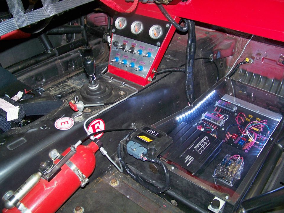
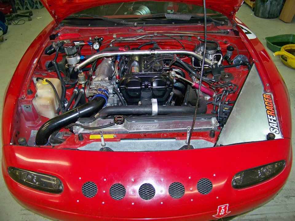
I have a 93 CAS using a custom harness that replicates a 93 engine wiring harness. The CAS operates Sequential AEM smart coils and sequential injectors and it works flawlessly. Surely this setup can trigger VVT. I have provided a picture below for reference, old engine in the picture.
SO, Can anyone simply list a set of VVC parameters that will allow VVT to actuate without damage to sensor or engine using my current setup and sensors? IF not, in laymen terms, please help step me through it.
Also, I found no information on which pin to use to power the VVT solenoid or which pin to use for sensor GND. Anyone have information on this? Either I missed it or it wasnt there.
Im looking for more of a one on answer to this, not a link to a page of past conversations.
Much obliged.
Last edited by jandjracing_58; Jul 23, 2014 at 09:31 PM.
Reply
0
0
Good Page, Good Information. But I ask why is this VVT setup so overly complicated. the valve itself is simple, Pulse width modulated magnetic engagement. If you can command VVT to advance at 2000rpm and disengage at 5000rpm yeilding to a max of 85% duty cycle, then whats with the pages and pages of insane technical detail for such a basic function. I know AEM is a fairly complicated software program but jeeesus. You will have to forgive my ignorance, im not trying to impress anyone here.
I have a 93 CAS using a custom harness that replicates a 93 engine wiring harness. The CAS operates Sequential AEM smart coils and sequential injectors and it works flawlessly. Surely this setup can trigger VVT. I have provided a picture below for reference, old engine in the picture.
SO, Can anyone simply list a set of VVC parameters that will allow VVT to actuate without damage to sensor or engine using my current setup and sensors? IF not, in laymen terms, please help step me through it.
SO, Can anyone simply list a set of VVC parameters that will allow VVT to actuate without damage to sensor or engine using my current setup and sensors? IF not, in laymen terms, please help step me through it.
Also, I found no information on which pin to use to power the VVT solenoid or which pin to use for sensor GND. Anyone have information on this? Either I missed it or it wasnt there.
Reply
1
1
Junior Member
Joined: Jul 2014
Posts: 71
Total Cats: -42
From: North Carolina
Excellent information my good sirs. Thank you for taking the time.
I learned that for my particular application the solution was a bit more simple than intake cam sensor triggering.
VVT 12v sourced from my main relay box. I have spare fused ports in my block. the VVT solenoid is 5 amp fuse protected.
VVT Signal to PW#2 (boost Control program)
Its controlled under these conditions:
244Hz fequency
VVT-on when throttle position more than 15% within 2500 to 4800 RPM range.
When within designated RPM range duty cycling controlled by KPA.
Min duty at 32%
Max 100%
So far so good, If anyone sees any obvious flaws in my logic please speak up, I wont get butt hurt.
Thank you
Reply
0
0
As long as you're OK with leaving a significant amount of performance on the table, that should work fine. VVT is a fully adjustable parameter, not just an on-off switch, and the ideal camshaft advance setting varies quite a bit. Full advance is not ideal at any RPM, nor is full retard, and the slope of the target map between ~3500 and redline is not a flat line.
It would be extremely simple to add a couple of wires to the injector harness, purchase a trigger wheel and a crankshaft sensor (you may already have both of these), make the necessary wiring changes, and set the software up so that you have full, 100% control over the VVT solenoid, instead of the on-off switch you're proposing.
It would be extremely simple to add a couple of wires to the injector harness, purchase a trigger wheel and a crankshaft sensor (you may already have both of these), make the necessary wiring changes, and set the software up so that you have full, 100% control over the VVT solenoid, instead of the on-off switch you're proposing.
Reply
0
0
Junior Member
Joined: Jul 2014
Posts: 71
Total Cats: -42
From: North Carolina
The duty cycle is variable and controlled based on KPA changes.
The program math tells me that my KPA changes as my throttle is opened and closed. As it changes so does my VVT duty cycle so long as its withing designated RPM range.
IF i wanted a VVT on/off switch i wouldve just wired it to a nitrous style WOT switch mounted on the TB
or use Boost program for 100% duty cycle past 15% TP only.
OR am i way off on my whole approach to this?
Reply
0
0
Junior Member
Joined: Jul 2014
Posts: 71
Total Cats: -42
From: North Carolina
Sure.
Ive been racing with NASA for 8 years. I race in Performance Touring E class.
My profession in ASE certified Master Technician
I suppose thats the good stuff. The rest of me is pretty boring.
Ive been racing with NASA for 8 years. I race in Performance Touring E class.
My profession in ASE certified Master Technician
I suppose thats the good stuff. The rest of me is pretty boring.
Reply
0
0
The duty cycle is variable and controlled based on KPA changes.
The program math tells me that my KPA changes as my throttle is opened and closed. As it changes so does my VVT duty cycle so long as its withing designated RPM range.
IF i wanted a VVT on/off switch i wouldve just wired it to a nitrous style WOT switch mounted on the TB
or use Boost program for 100% duty cycle past 15% TP only.
OR am i way off on my whole approach to this?
The program math tells me that my KPA changes as my throttle is opened and closed. As it changes so does my VVT duty cycle so long as its withing designated RPM range.
IF i wanted a VVT on/off switch i wouldve just wired it to a nitrous style WOT switch mounted on the TB
or use Boost program for 100% duty cycle past 15% TP only.
OR am i way off on my whole approach to this?
 )
) The flaw in your logic is this: there's no linear correlation between duty cycle and intake cam absolute advance. If you set the duty cycle to 60%, it does not target a specific advance number - it continuously advances the intake camshaft until it's reached full advance. If you then target 10%, it will continuously retard the intake camshaft until it reaches full retard. In order to actually adjust it, the ECU needs to increase the duty cycle until the target cam advance is achieved, and then immediately reduce the duty cycle to ~30%, which is where the cam is neither advancing or retarding. The only way to do this is with a full closed-loop target table that measures the current cam advance, commands the solenoid to either advance or retard as needed, and then returns the solenoid to its neutral position until it's needed again.
Reply
2
2
Junior Member
Joined: Jul 2014
Posts: 71
Total Cats: -42
From: North Carolina
I understand. Then I shall alter my method and try again. My old motor is from 96 and i do have a 4 tooth crank wheel behind the main pulley and the new motor has Cam angle sensor, which works best?
Also, its say i have -1 props. Whats that mean, people like me already?
Also, its say i have -1 props. Whats that mean, people like me already?
Reply
1
1
Junior Member
Joined: Jul 2014
Posts: 71
Total Cats: -42
From: North Carolina
There's a lot I do not understand when it comes to the manipulation of components to make an engine work properly.
I'm best in diagnostic and repair. That is how I afford the things I love. I could tell you why your vvt failed but I couldn't write the parameters by which is operates. I suppose I will leave that to those more inclined than me. I've never had a teacher to show me what's important and how it works.
As a driver, car enthusiast and technician I can only split my energy in so many ways. I choose to be the best at what I do know rather than spread myself to thin while trying to learn everything.
As for the short post on who I am that Mr. Monk requested, this is the real answer. I'm just a mechanic trying to learn more than I do now.
Reply
0
0
Mr. Monk is my father.
Positive props are given when a post is very helpful and/ or humorous. Negative props are given to posts that are distasteful or against forum rules.
When I mentioned starting an introductory thread, I meant that you should post it separately in the meet and greet section. You can find it under the tab that reads "forums".
It is generally not a good idea to post in threads that are very old, although your discussion with Sav has yielded some good info.
You have a good attitude, you just need to read the forum rules carefully. Go ahead and post a separate intro thread in the proper section, and post some pics of you car there. Make sure you read the sticky on how to do this properly.
Good luck, and props to Savington for being a boss.
Reply
0
0

Thank you all for the thoughtful discussion. I have not used a VVT head yet but I now know how they are manipulated to advance and retard them.
Jeff has now posted a meet and greet thread with pictures in the appropriate section so everyone can go say hello.
Jeff has now posted a meet and greet thread with pictures in the appropriate section so everyone can go say hello.
Reply
0
0

Thread
Thread Starter
Forum
Replies
Last Post
StratoBlue1109
Miata parts for sale/trade
21
Sep 30, 2018 01:09 PM
JesseTheNoob
DIY Turbo Discussion
15
Sep 30, 2015 02:44 PM


