When you click on links to various merchants on this site and make a purchase, this can result in this site earning a commission. Affiliate programs and affiliations include, but are not limited to, the eBay Partner Network.
It's a sandwich panel. Aluminum has an elastic modulus. Polypropylene has an elastic modulus. You do not actually care about the elastic modulus. Modulus is analogous to density; it does not account for geometry. You care about the bending stiffness, which comes largely from spacing the aluminum apart.
A sheet of steel that is one thousandth of an inch thick has a much higher elastic modulus than 10mm Alumalite. It is also much less stiff in any way you'd care about.
Good napkin estimates of the bending stiffness of Alumalite can be obtained by modeling it as an "air core," where you only have to analyze the face panels. It depends on the loading, though, so you should figure out what parameters of deflection you actually care about.
Thank you for supplying my Giorgio Tsoukalos picture to my identity.
I have been asking about the modulus because of a post between Emilio and I quoted below. It is because of this I ask. I think he makes a valid point for materials being chosen on the failure mode.
Originally Posted by emilio700
Modulus key.
Failure mode also important.
Does it stay bent or shatter.
Abrasion resistance.
Cost per square/ft.
Before Alumalite, birch was the next best thing to Tegris or dry carbon.
I have been working on this based off of some rough numbers i was able to get real quick. Right now the total weight is 32lbs according to solidworks which seems heavy.
This is not anywhere near a final draft. This is more of a conceptual thing that we can spit ball off of until we have a good design. Then i will post up all the drawings to DIY in a new thread.
Edit: Forgot to add materials. the barge boards are 6mm alumalite, Flat bottom and diffuser is .040 aluminum with 1/2"x .125" thick aluminum angle, mounting tabs are 1.75 and 2" C-channel that is .125" wall and unsure of final outboard angle dimension at the moment
Looks very good, though I think you're gonna need more trans cooling ducting; the transmissions on these cars already run hot. Unless of course you're planning some type of oil cooler for the tranny [and diff]
In the doodle now there are 2 3" naca ducts that can be routed to the diff and for the trans i plan on adding some ducts way far forward in the splitter area. Then way way far in the future bmw trans and getreg diff that will get temp sensors to actually measure where im at.
What exactly are you asking in the first question?
Your picture update perfectly demonstrates.
Little one has been sleeping badly for four days so i'm quite frazzled. I was asking if the diffusers were pointed at the tyres and how effective that would given the turbulence off of tyres.
The design is roughly what I am hoping to produce but the diffuser will sit under a bumper and only project a very small amount.
I've found C channels to fit to my frame rail bolts but I'm not sure how to sort the butterfly brace section yet.
The angle seems sensible but the pinch weld parts aren't very deep 10mm at best so I'm not sure where to attach that section.
Has anybody done the angle attachment style from the diagram and can provide a close up?
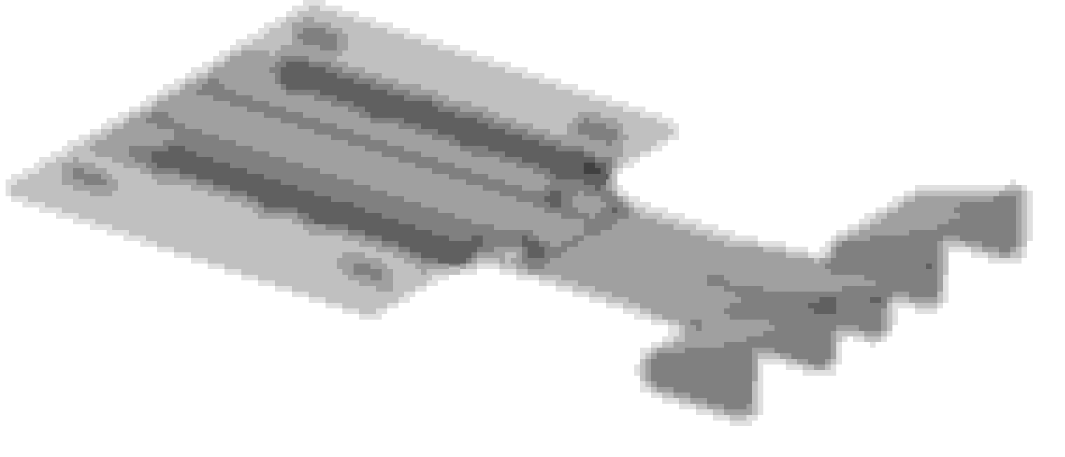
Terrible photo of Cody Loveland's Honda hatchback floor and barge boards. Interesting how he brings the fins for the barge boards almost all the way in to the vehicle centerline. The other interesting thing he does (and sells) is a large 2D front wing. There is no flat portion at all on the underside (i.e. its not flat with tunnels), just a relatively thin profiled wing, which is also the same type of setup he runs on the Enviate to my knowledge. Consequently, on the hatch, there is an airgap between the wing and the leading edge of the flat floor/barge boards.
Where is the seam on the floor/ how do the pieces break apart for removal?
you get cats when I get to a computer
Seams are in each wheelwell.
splitter is a 4x8 sheet of 10mm Alumalite, splitter butts to floor.
floor is 2 4x8 sheets of 6mm alumalite, very small overlap and is a one piece removal.
Diffuser butts to floor.
That is freaking awesome. Why did you use alumalite and not wood for the splitter? Are the slits in the center for exhaust heat?
Alumalite has a much better stiffness to weight ratio than Birch ply. Yes the slots heart to help evacuate Heat from just under the exhaust. We folded the leftover flaps down to create a bit of a gurney. This helps create a low pressure over the opening and draw the air out. This extraction disturbs under body flow so we made them very small and only three.


 0
0