When you click on links to various merchants on this site and make a purchase, this can result in this site earning a commission. Affiliate programs and affiliations include, but are not limited to, the eBay Partner Network.
A little tip I learn from talking with a thermal insulation supplier at work, make sure you seal the edges of the insulation with high temp liquid silicone or a sealing tape (like aluminized tape). The foam/composite materials will absorb moisture and oil and can break down overtime.
Thanks for the tip, but I took the insulation out in favor of putting it underneath the carpet. The undercoating of the car prevents the insulation from sticking well.
Over the past few days since the last update I have got the engine in the car. Before I got the engine in, I touched up a few things. First I added a P clamp to the water line from the mixing manifold to turbo and covered the upper P clamp in heat insulation.
Then mounted the alternator, remote oil filter housing, and the oil pressure sender from my 1.6. However, I "broke" my sender unit, and the outer ring broke free of the base of the sender. I'm worried about the electrical connector on the top, seeing as it spins with the outer ring. I don't want to break in a brand new motor with expensive break-in oil with a failed sender, so I ordered a new one. I will try the sender out on my second Miata when it get's it engine put back in, as I know that engine is healthy.
Another part of the 1.8 swap is the different TPS, and the connector. The 1.6 is a 3 pin while the 1.8 is a 4 pin. I called a few junkyards and Miata specific junkyards and they either didn't have a Miata or wanted to sell me the entire engine bay harness. So, I took a chance on a Wells 599 connector from Amazon. The connector had a Mopar official parts sticker on it, but seems to work from a test fit.
Then I put on my FM clutch and flywheel. The old pressure plate bolts I had were actually a different thread pitch, as they came from an ACT flywheel, so I had to go the ACE hardware to get new hardware. Also, I had to get another starter motor bolt as well as another transmission bolt that I lost.
Then, just this evening, I got the engine bolted in.
I'm currently waiting on the new oil pressure sender, an extended clutch line (I have a SS one the replaces only the stock rubber line, but want to delete the curled line too), and new turbo compressor flanges to be able to start it up.
Quick update, to do the 1.8 swap I need a few wiring mods and a new throttle cable or new bracket. I chose to make a new bracket out of some aluminum bar stock.
Next, my new OEM oil pressure sender came in from priority Mazda and I got an extended length clutch line from 949.
Now for the wiring mods. The first thing to do since i'm keeping the 1.8 TB is to replace the TPS and IAC connectors. The IAC I was able to find as an assembled pigtail and it went on without a hitch. On the other hand, the TPS I had to assemble, and the wires do not sit in the connector tightly. For now, I wrapped the ends with electrical tape, but I may try to put a dab of hot glue in them. If anyone has any suggestions or has an OEM pigtail, let me know. The second wiring mod is to extend the CAS sensor wiring, and that is pretty straightforward. Lastly, I had to enlarge the ring terminal on the alternator ground.
I knew as soon as I put the AC compressor on that my water lines from the mixing manifold would hit the belt. To remedy this, I took off my tee and put in another "failure point", a 90 degree fitting. I still may get a 180 degree hose end, but this works for me.
Next, I redid the wiring for my TPS, the smaller gauge wire that came with the kit didn't want to lock into the connector, so I used the larger gauge wire instead.
The last thing I got done today was mounting the coil pack. In hindsight, I should've made a mount before I put the engine in, but oh well. I made some L brackets to adapt the 1.6 coils to the valve cover of the 1.8, but didn't like it. So naturally, I went ghetto with the mount. I cut up my 1.8 bracket and since I could only get 1 bolt hole to line up, 1 of the coil packs is ziptied on. This setup is only temporary as I am going to a COP setup after I get the engine running. For now I don't want to throw a bunch of new untested parts on, and then have a hell of a time troubleshooting any issues.
I have everything except an exhaust setup for this car. So for next week, I get to make one, or give up and order an overpriced FM/Begi one...
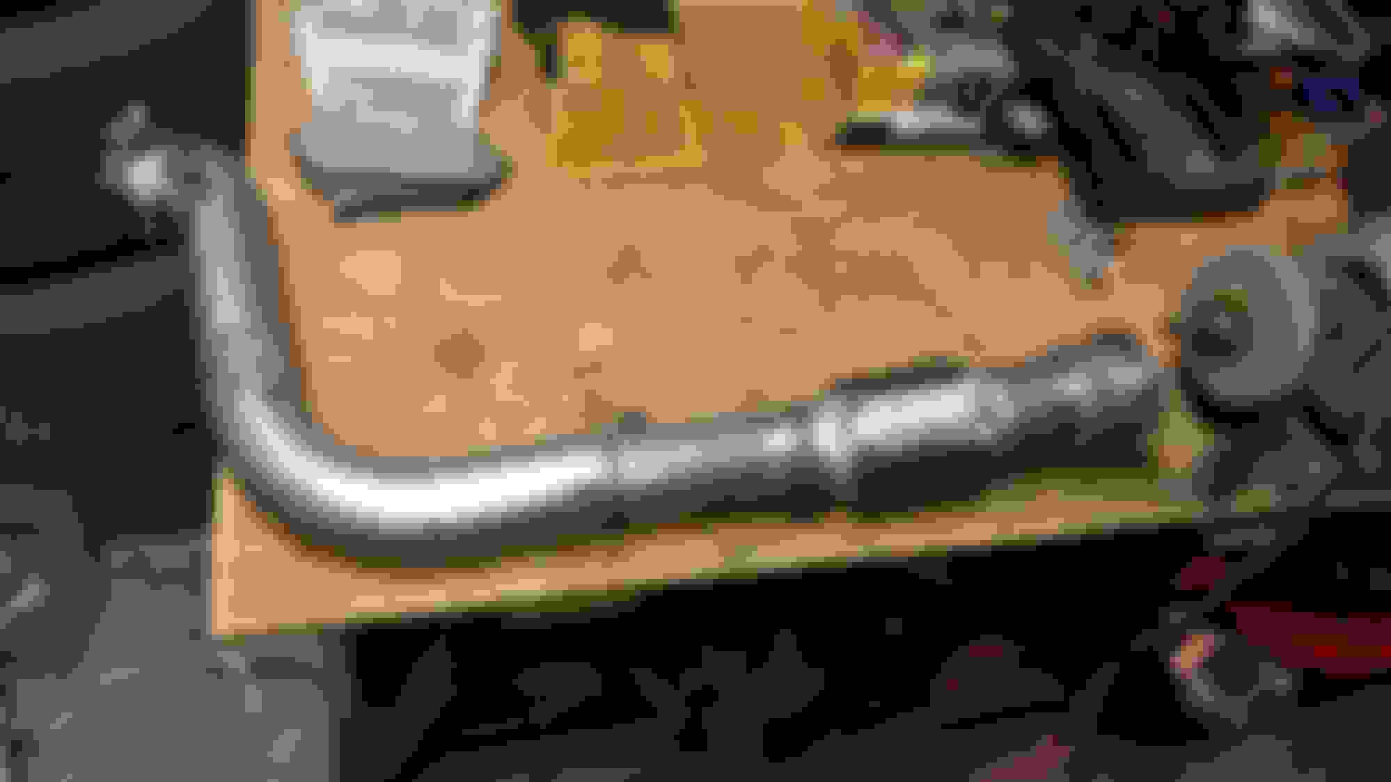
So, I fabbed up a downpipe with some welding help from my dad. He has a MIG welder so the welds aren't as pretty, but a grinder and paint fixes that up. Since the FM manifold places the turbo in the middle of the exhaust runners, I decided to make a 2.5" downpipe that tapers into a 3". To start, I cut the flange off my old 3" downpipe for my 1.6, and got a U-J pipe, flex joint, 2.5" to 3" reducer, and a couple V bands. I also picked up the 22x11x5 Magnaflow muffler that is popular here.
I ground down the welds on the turbo flange, but I formed a hole in the side where I had a second piece of pipe connect to my "cheater bend". To remedy this, I welded on a reinforcement plate that doesn't look the prettiest, but should hold up.
Then used the rest of the U-J to make the downpipe. Since I made a cheater bend off of the 5 bolt flange, I had to make the straight section after the second 90 go at an angle to bring the flex joint parallel with the ground. I made sure to keep this downpipe tucked as far up as I could, as my other Miata had a flattened exhaust from being too low. To finish off the pipe, I sprayed it in some VHT black header paint. Next, I will finish the midpipe and hang the muffler, then be able to start the car, and the break in process.
Since the last update I have completed my exhaust setup and have done a few other things. After the downpipe, I went to a full 3 inch with the MT.net approved Magnaflow muffler. I added a fourth exhaust hanger as this thing is big. I didn't want to weld directly to the car, so I made a plate that bolts over the factory rear tow hook for the fourth hanger. After all was said and done, I replace the rubber hanger on the fourth hook with a poly hanger.
Then, to match the downpipe, I painted the mid pipe and side the muffler with VHT header paint.
While waiting for the paint on the exhaust to dry, I took another shot at the wrinkle paint on my valve cover. It's not perfect, but it's the best wrinkle job yet. To finish it off I sanded down the letters.
I didn't like how my reroute hose touched the throttle body, and was an eyesore, so it was swapped for a GM rad hose. I wish there was a multi-layer silicone version of this rad hose. I also added a FM lower rad hose as my NB hose fitment was really funky.
Today, I bleed the clutch, filled the car with coolant, and filled it with my fancy Joe Gibbs break-in motor oil. Then, when I went to set the base timing, my timing light wouldn't work. I thought it was because of my Magnacore wires, but even stock wires didn't work. Eventually I found out I have no spark, I didn't blow any fuses and all of my wiring/grounds are good, so i'm going to get another coil pack to try tomorrow.
Since the last update I have gotten the car to run. I'm still unsure what exactly was wrong, but reloading the base map and holding the gas pedal to the floor to start the car allowed it to start. Since I didn't have an intercooler pipe setup yet I made a ghetto air intake for the engine break-in process. Furthermore, I calibrated my vTPS, fixed a small coolant leak, fixed a small oil leak (forgot to put the RTV in the corners of the valve cover), and found out my transmission has a small leak . Its leaking gear oil where the tail shaft casing bolts to the center housing of the transmission. That's gonna be a job for the winter time. Finally, I also had a cam gear jump a tooth, and I scooped up a Garage Star water pump pulley anodized gold.
I have now moved on to making my intercooler pipes. I couldn't get a nice routing on the coldside, so I made a bend to clear the rad hose, and have enough room for the IACV hose. If I get a cross-flow rad, I'll redo the coldside, but its fine for now. On the hotside, I had the problem of my turbo's outlet being too long to clock the compressor downwards. For the intercooler mounting, I copied the FM method of aluminum strips bolted between the hood latch running down. The intercooler is a little floppy, but with the pipes on, it is secures fairly well. The intercooler pipes just got welded up today, so I'll get some pics of them all cleaned up and installed later, but here is a pic from the mock-up stage.
The last major step is the make a custom bumper to heat exchangers shroud and cut up my undertray to fit.
Another small update, I have finished my intercooler piping and intake setup. Here is a general overview of the finished setup. I will add a catch can later, but for now I have the valve cover vented back into the intake.
The cold side pipe hides the IAC hose, so here is what it looks like out of the car. The IAC hose is just a generic 90 degree 3/4" heater core hose cut to fit. Test fitting this has already ruined my quick spray paint job, but oh well.
My intercooler is made out of ridiculously thick aluminum, and to avoid heat soak, I placed the IAT in the coldside of the intercooler. Since the intercooler may hit my AC hard lines, I wrapped them in the excess heater core hose from my IAC hose I made.
As mentioned in the previous post, I am waiting on a HDPE panel I ordered from Menards to make a custom undertray and rad/intercooler ducting. It was $30 for a 1/8" x 4' x 8' sheet. I also am waiting on a Compressor housing clamp kit, and I have to modify my wastegate bracket to fit.
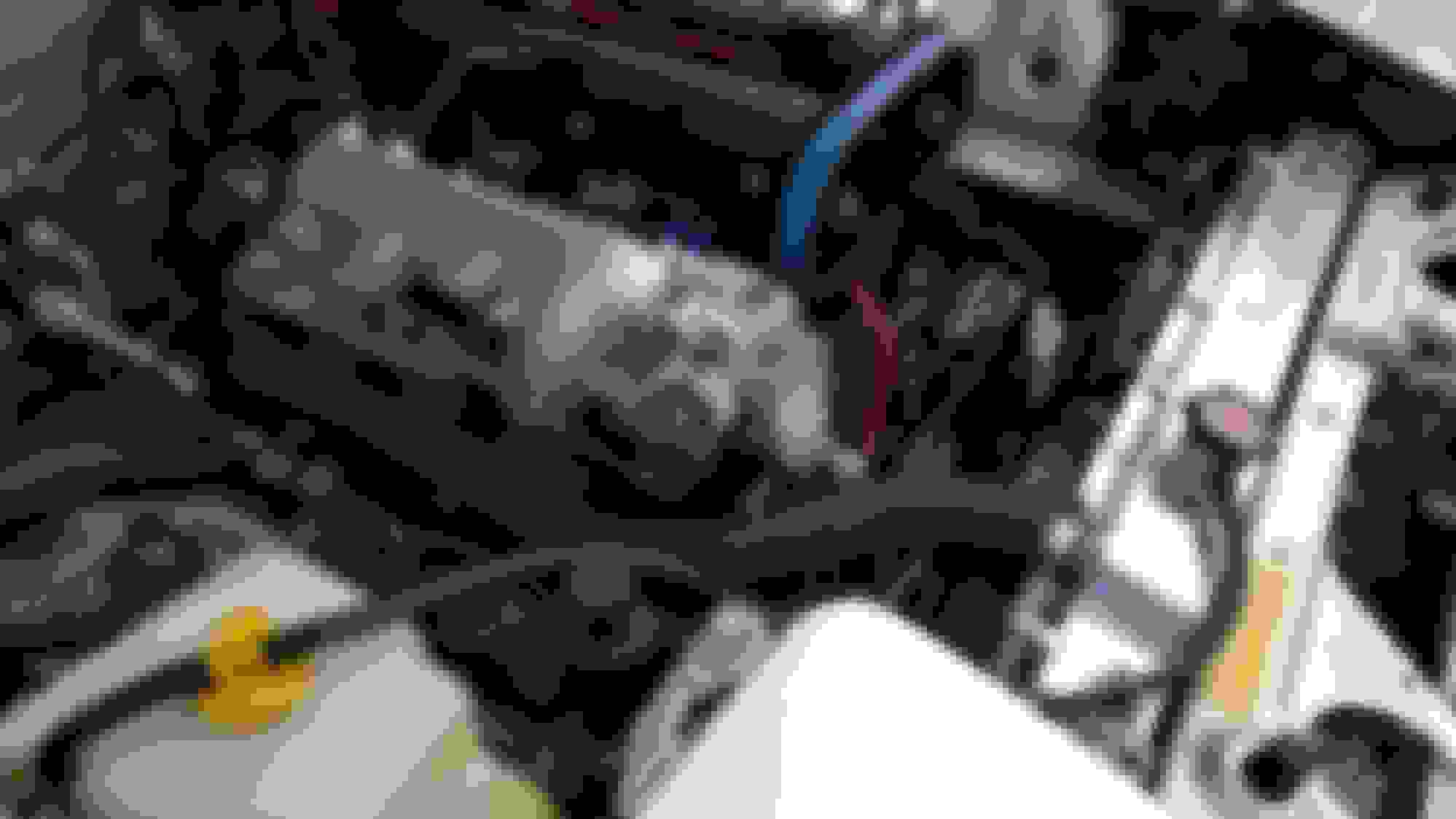
I have done a few small things since the last update, namely mounting my waste gate actuator with a custom bracket I welded up. I had to get a new compressor housing clamp kit from atp turbo first though, since my previous clamps were hacked up by a previous owner of the turbo. To mount the actuator, I reused the circular mounting bracket off the original mount, and extended it forwards with some steel bar. Then welded that to the only good old compressor clamp. The can of the actuator slightly rubs on the compressor housing, so I drilled two new holes slightly higher up to prevent this. I finished the bracket off with some flat black bbq paint.
The turbo also came with a HKS actuator, which is rated for .5 to 1 bar (7psi to 14psi). Since I am still under the break-in mileage, I have it set to no pre-load, so ~ 7psi. I am going to add electronic boost control after I get my drive train properly broken in. I also added heat sleeve to the valve cover vent hose while I was in there.
I also got my HDPE sheet in from Menards, $43 shipped for this giant sheet isn't bad. I have made mock-ups of the sides of my heat exchanger ductwork so far, I need to get a jigsaw tomorrow to start cutting it out. On my passenger side, I am trying to add a removable cover over the IAT sensor, so I can service it if need be, without having to remove the entire ducting. If anyone has suggestions other than a plate with self tappers over a hole, let me know. I don't think a tap will work well on this material to have a removable plate bolted in.
The car is now put back together. I bought a jigsaw, made the under tray, and bolted the bumper back on.
First, I made a mock-up with cardboard, and then transferred to the HDPE. I tried to make a one piece tray, but the bending proved to be too difficult. The tray is held together by L shaped brackets riveted on to the sides. Since this left a small gap on either side's bottom, I covered both the top and bottom in aluminum tape. Then I used some foam strip to seal all of the edges, and made a cutout for the radiator drain.
When bolted in, the tray was flimsy as it was held in by two bolts, and an overlap of the front splitter. To reinforce it, I took inspiration from Eunos91's undertray and made brackets to connect to my radiator. Since I have A/C, the hard lines are in the way of one would be bracket. To remedy this, I replicated the factory L bracket, and made an extension for a factory P clamp to secure the A/C lines.
Here is what it looks like all bolted up.
The car is able to idle, but needs a proper tune, and does not like hot starts. I am on the lookout for any Dyno tuners experienced in MS and/or Miatas in the Iowa/Illinois region.
The hot start issue has been fixed with some MAT correction, for some reason the IAT sensor would still heat soak when located in the coldside of the intercooler. Adjusting the MAT correction to 100% all the time fixed it. These past couple morning have been cold, so I have been able to dial in the WUE a bit. It still isn't perfect, and I believe the cranking pulse needs to be adjusted still. Sometimes when cranking I need to give the car a little throttle to get it started. Furthermore, I did the car's first oil change on the new engine this morning as well. Since I'm still under the 500 mile mark, I am using Rotella T4 10W30, because it is a conventional oil. I will switch to T6 when I am able to run full synthetic oil. I am sending out an oil analysis to Blackstone and will see the results of my break-in oil. The Oil had about 30 mins of 2k rpm and ~15 miles of various speeds and coasting in gear to stops for ring seating.
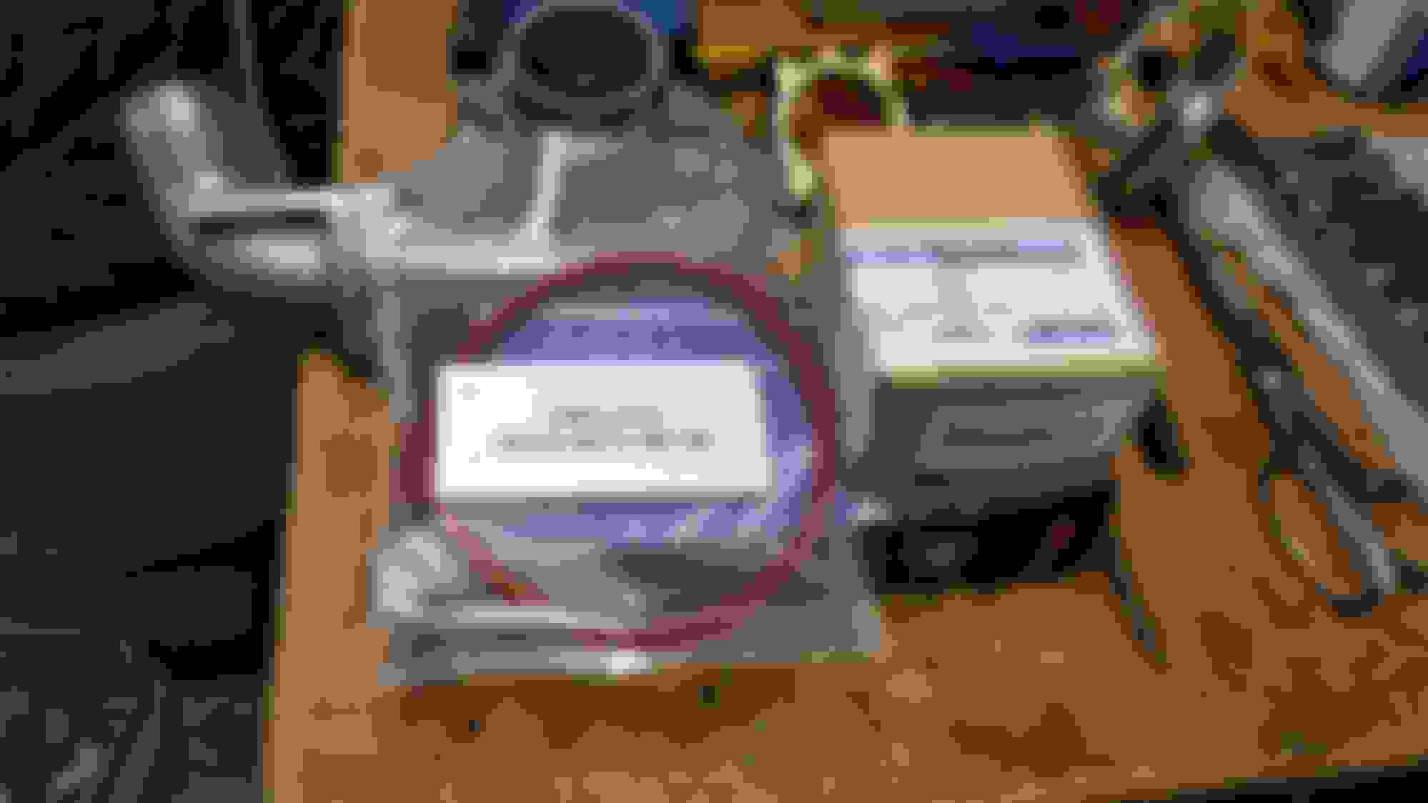
A couple of weeks ago I picked up the Big Brake for sale from another forum member. The kit is a Trackspeed 11.75" front and sport rears, along with a sport booster and 929 master.
I have been waiting to install these for awhile, just have been waiting on some ATE to come in, which finally arrived today. I'll snap some pics of these installed later on.
EDIT: Forgot to include this small project. I have had a hole under my radio for approximately a year now, since I put a new headunit in that has an aux cable, and it has been really bothering me. I have a bunch of left over HDPE, so I made a quick plate that covers the hole. I didn't want to screw the plate into the back of the tombstone so I used the 2 lower screw holes for the radio and added some nylon spacers to make the plate flush with the opening on the tombstone. The radio structure and tombstone are at different angles, so the top has a small gap, but I can live with that.
Another note, I had a small coolant leak from my M-tuned thermostat housing, and a leak where I sourced a turbo waterline on the M-tuned outlet. A new thermostat O-ring and thread sealant fixed these leaks, but was a pain to get to the turbo waterline. Then, after I burped the cooling system, my radiator cap was not seated all the way and blew off the radiator. Now, 2 days later, I am still finding coolant in my engine bay .
Last edited by Docterhow; 11-01-2017 at 05:53 PM.
Reason: Added picture
Well, like a month later, my brakes are finally installed. I had one hell of a time, I broke a brass adapter fitting for my prop valve, UPS almost lost my ATE brake fluid, and UPS also delivered a new rear junction block 3 days late. A one day install turned into a 2 week install. With all of that out of the way, these brakes are pretty awesome. As mentioned in a previous post, the brakes are a Trackspeed 11.75" with Wilwood dynalites on the front and Mazda sport rears. Also included was a sport booster, 929 master cylinder and Wilwood adjustable prop valve.
To start, here are my old crummy 1.6 brakes and booster/master. Pretty boring and ugly stuff, right?
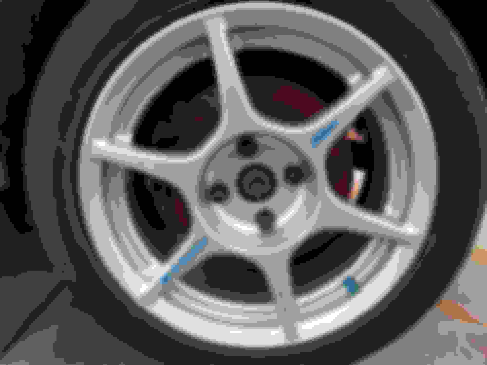
Now here are the Trackspeed fronts installed. If not already known, 15x7 Kosei K1 with +30 ET fit these monsters.
And the sport rears installed.
Now onto the booster/master stuff. As a side note, getting the booster out was a pain due to the top left nut being buried deep under the dash. Anyway, I wanted to do some heat management for the brakes, so I wrapped the "new" master and brake lines in some gold foil. Also note that this is a 929 master cylinder, which has a 1" bore, but only 2 outlets, so a tee fitting is used to connect the font brake lines since I do not have ABS.
However, the factory front left brake line will need to be bent to connect to the tee fitting.
I could've bent the factory line, but it turns out my dad has all of the brake flaring/cutting tools in addition to a collection of random hardline laying around. So, I made a new front brake line instead of bending up the factory line. I also wrapped the upper portion of the new line in gold foil. I ended up having to change out the lower tube nut with a different one as it was the wrong size, but this lines looks a lot cleaner in the engine bay than the factory line.
Here is the new booster, master and prop valve installed. I'm going to add a support bracket for the prop valve later by either bending the factory one or making a new one. As you may notice in the picture below, I have a remote bias adjuster installed, with the cable running through the firewall in that ever so convenient spot.
Here's a bonus picture of the carnage from the brass 1/8 npt to m10 adapter that was replaced by the Trackspeed adapters (made from steel ).
Then, the remote adjuster cable was ran to my under-radio blanking plate. To get the cable to work, I had to add a 1/4" vacuum hose as a sheath along the length of the adjuster cable, otherwise you'd have to turn the about 5 clicks to get the prop valve to adjust. I left some room on the plate for future oil temp and proper water temp gauges.
So, after all this time, the car has been broken in and now has brakes to match the power of the car. I'm looking into getting a professional dyno tune to see how much I can get of this turbo, so if anyone has recommendations for the Iowa/Illinois area, let me know. I wouldn't mind having to take the car to Chicago if need be.

 08-14-2017, 09:30 PM


 0
0


 . Its leaking gear oil where the tail shaft casing bolts to the center housing of the transmission. That's gonna be a job for the winter time. Finally, I also had a cam gear jump a tooth, and I scooped up a Garage Star water pump pulley anodized gold.