
2jz Miata build thread


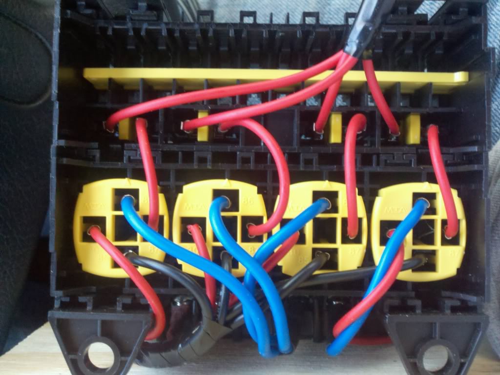
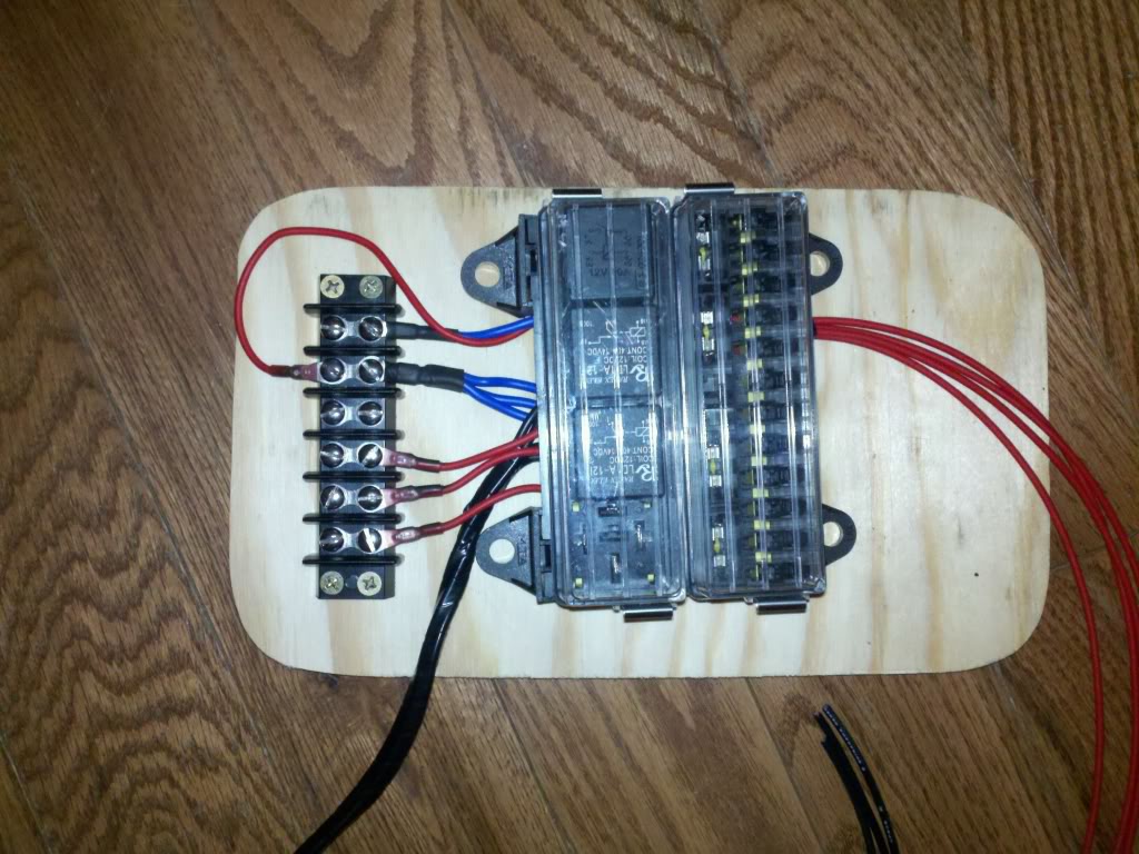
Ok here are some more pics. I finished wiring this up last night I am sure I will have to add some more fuses to it later but for now it is what I need. I may get rid of the mazda fuse box all togeather now that I have this but that will come later. What you can see in the pics is the 4 fuses that power the respective relays and the first relay is a key on relay that turns on the other relays with will run the FI/C, and the toyota engine harness and ecu. Should work really good when installed. All I need is my power buss to feed it all and I need to get a connector for the ground wires.
Reply
 0
0

0

Blue wires are the relay on signal wires, red wires are power in and power out, and black wires are the ground.
Faeflora - It makes it easier to use different color wires when you have easy access to them. I walk into the trailer and get what I need you have to order it or go to the store and get it.
Faeflora - It makes it easier to use different color wires when you have easy access to them. I walk into the trailer and get what I need you have to order it or go to the store and get it.
Reply
0
0
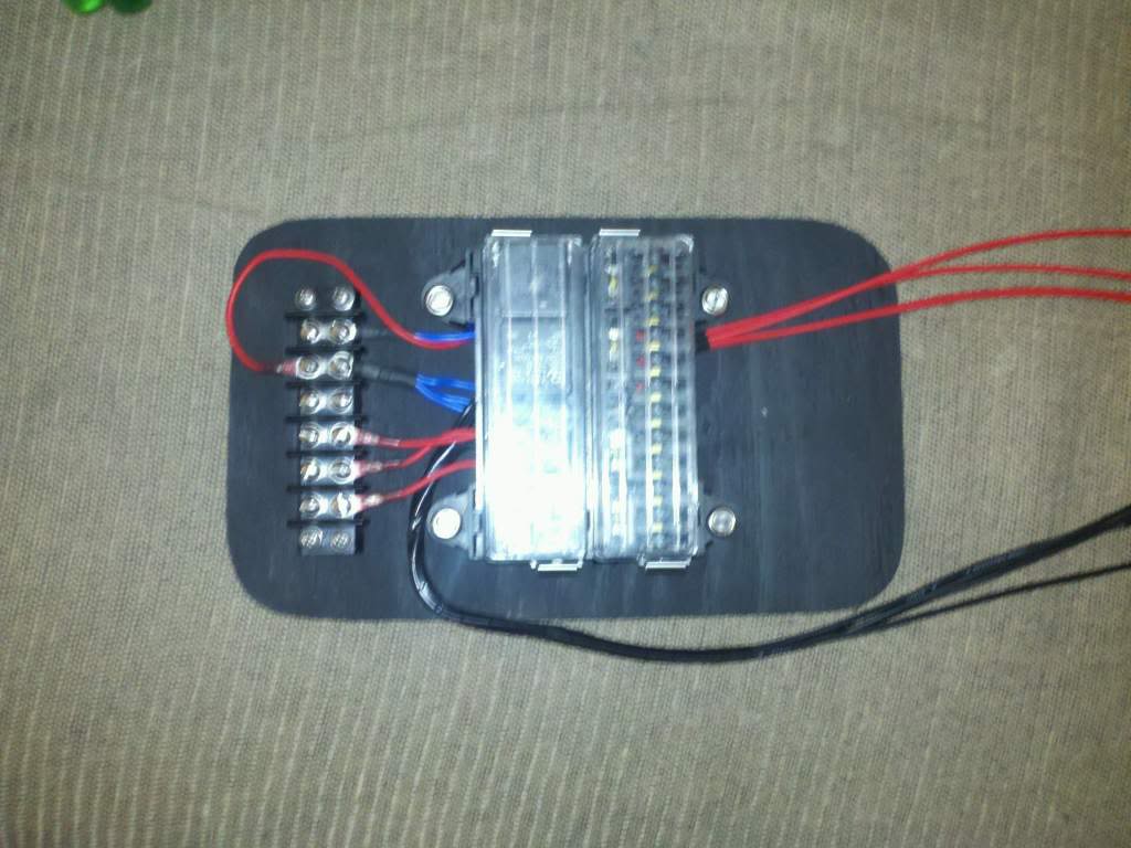
Ok two good things to tell you all. I got my fuse/relay box all done just need to install it with my harness. I also leaned how to use my FIC a little bit.lol I have never used anything like this before but I am sure it will not take long to learn. I am going to be messing with it out of boost first but now that I have figured out how to get into the maps I think I am going to be ok. I need to order a new laptop battery too so I can tune in the car.
I made a base cal using the software just by inputting my injector size change and I am hoping this will help to get it close enough to start the car then I can work it from there.
Here is a pic of my fuse/relay box all mounted and painted.
I made a base cal using the software just by inputting my injector size change and I am hoping this will help to get it close enough to start the car then I can work it from there.
Here is a pic of my fuse/relay box all mounted and painted.
Reply
0
0
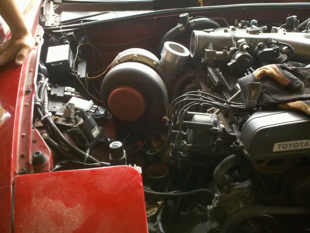
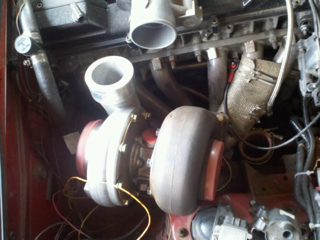
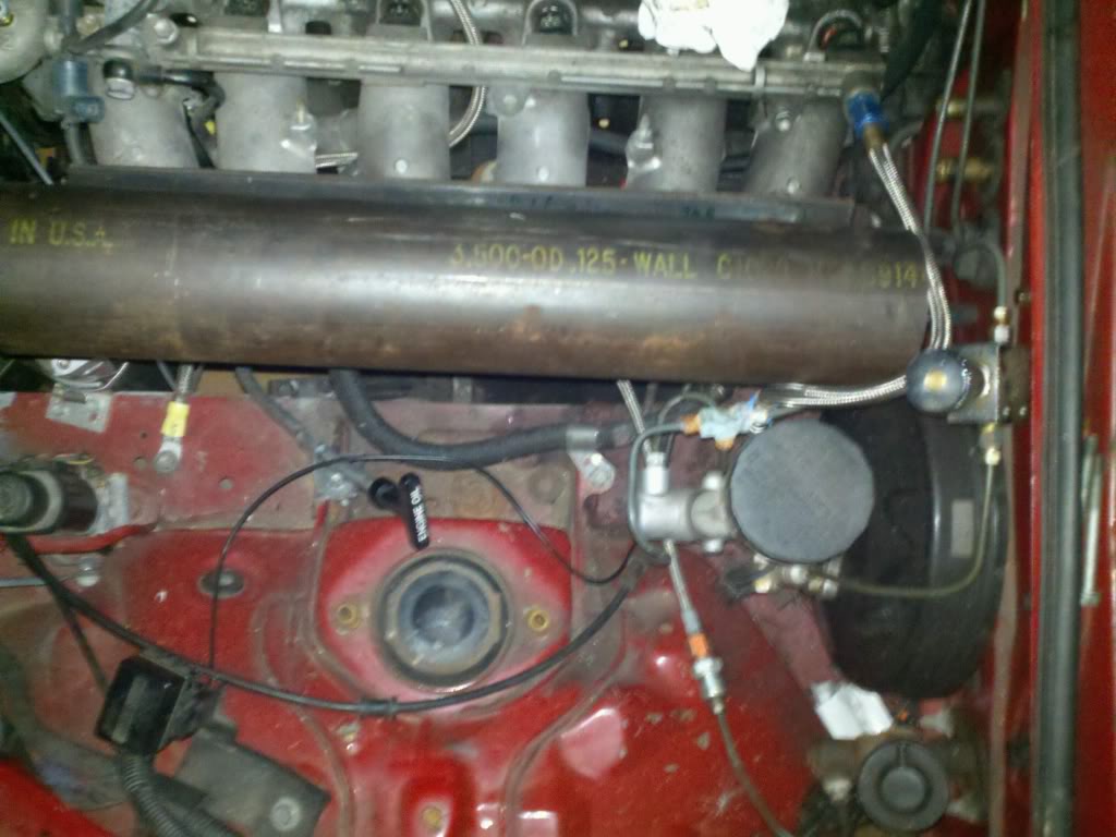
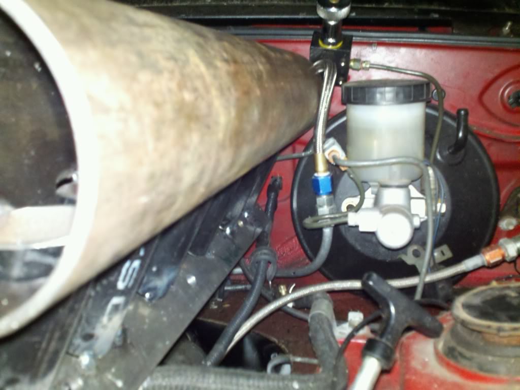
Ok so here we go on another update. I took my turbo down to mock up on my car this weekend and what do you know it is no where close to fitting the normal way. So what is the next best thing to do on a turbo that does not fit you ask. Well you turn it around. So I have already started getting the parts to make a front facing intake manifold so now I am just going to take all those parts and make it a rear facing manifold. I will be cutting welding and remaking my intake manifold like crazy so it faces the firewall. The turbo piping will come out of the turbo into the wiper cowl and the across to the drivers side then back through the wiper cowl and into the rear facing intake manifold. I know this sounds crazy but I am going to get a really go meth injection kit with a progressive controller. I do not like the idea of all sorts of pipes running everywhere and this is my best solution. I was going to need meth at some point anyway so this just pushes me to that point. As far as building an easy 350whp that has gone out the window. We will now be searching for more like 550-600whp and this will leave room for improvement. Also by mounting the turbo backwards this gives me room to go with an even bigger turbo if I feel the need. So sit back and enjoy the show because this **** is about to get crazy.
Here are some pics from the mock up.
Oh and before you ask when you mount the turbo the normal way it hits the head as well as the distributor so this is gonna work out great!!!
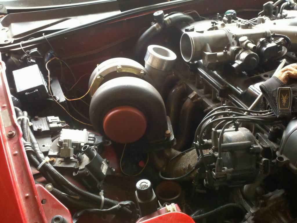
Here are some pics from the mock up.
Oh and before you ask when you mount the turbo the normal way it hits the head as well as the distributor so this is gonna work out great!!!
Reply
0
0
Are you doing away with the factory fusebox? If so, would another option be to cut down the compressor outlet and route the charge piping over the shock tower? Or, go through the fender?
Reply
0
0
Yes the factory fuse box will soon be gone and rewired under the dash with my new fuse box. I looked into runing the piping through the fender but it does not seem there is enough room in there. Also to compound the problem the exhaust will now have to come through the front of the fender leaving even less room, but with the piping through the cowl I can remove the intercooler move the radiator forward and then the exhaust can come out the lower part of the front bumper.
Reply
0
0

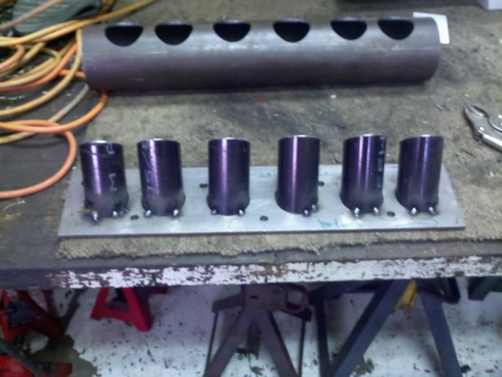
Ok so after many debates over what to do with my intake manifold and not knowing how to weld aluminum and being a cheap ***. I am going to build my own steel intake manifold. I do not have money to waste for someone else to weld my aluminum intake so I will make it out of steel and when its all done I imagine it will not be much heavier than the one I was making out of cast aluminum. Here are the pics of the material I will go tonight to see if I wanna run a 3.5" or 4" runner depending on space and tomorrow make a flange.
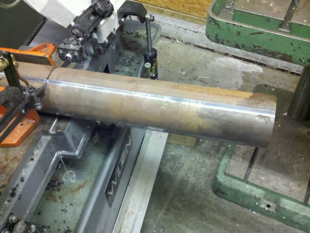
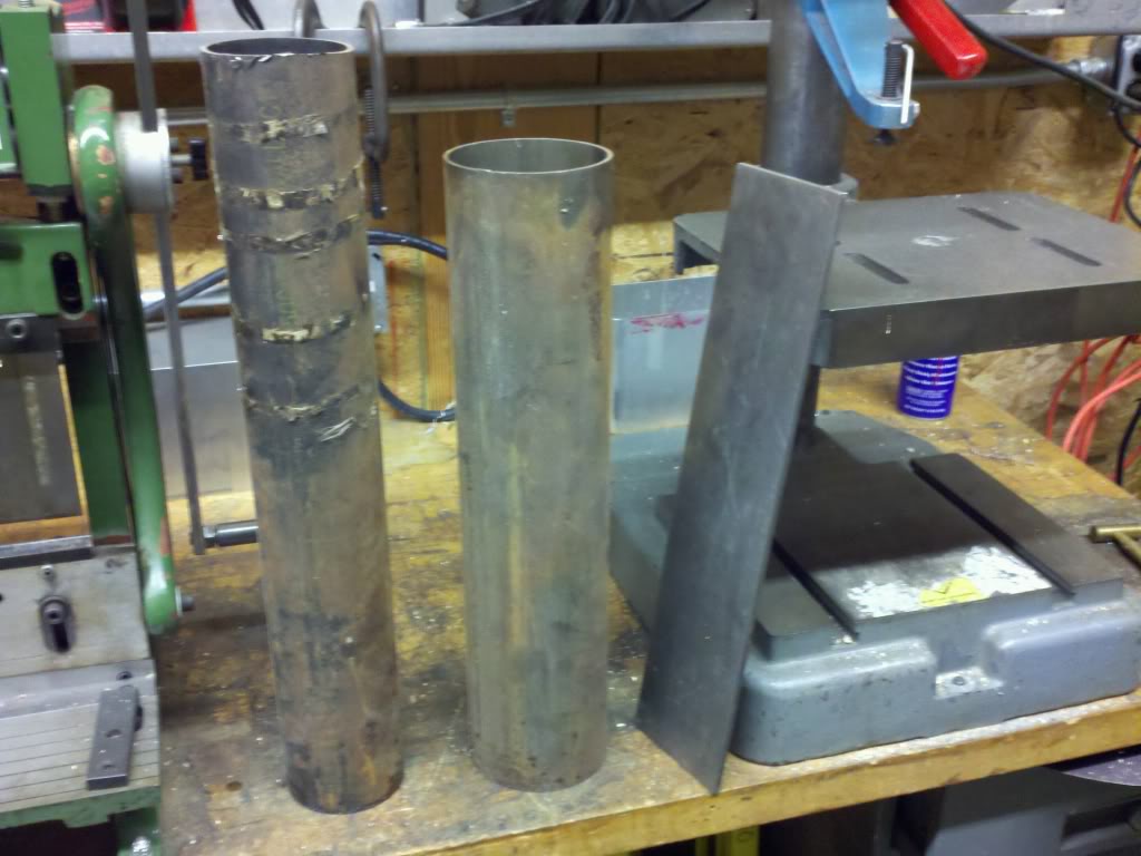
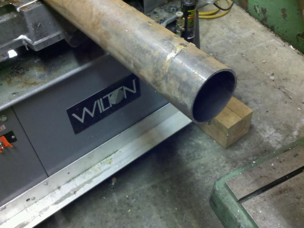
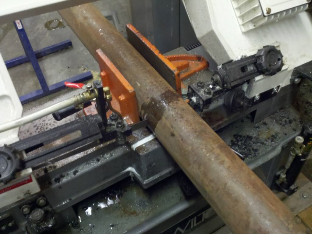
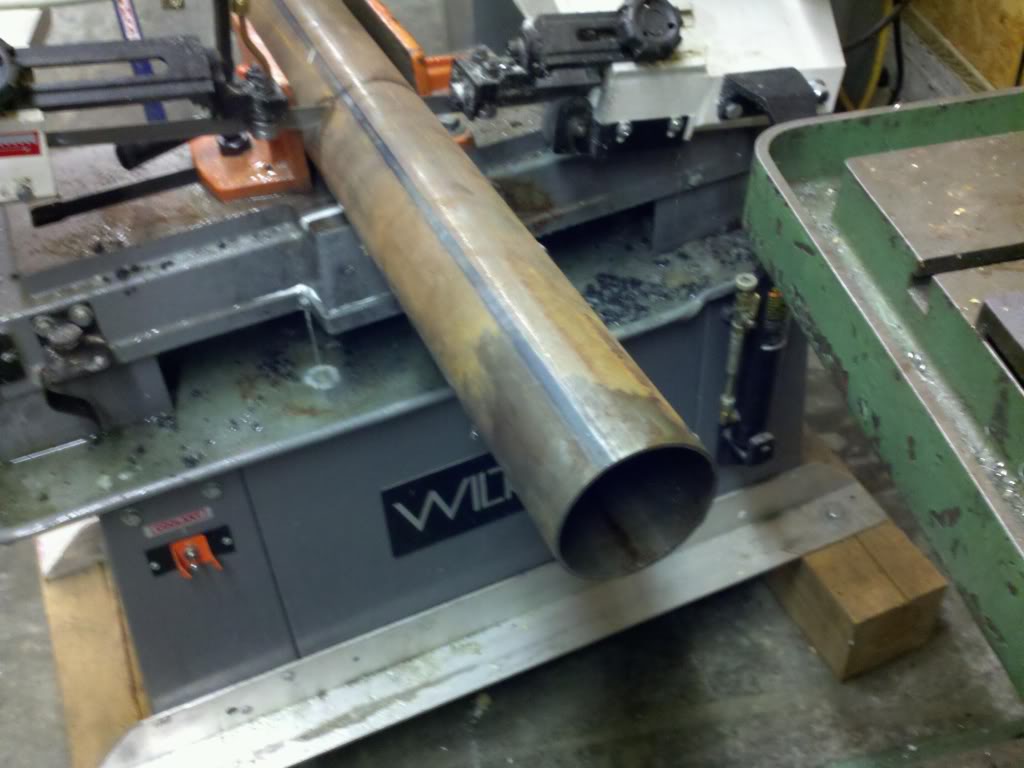
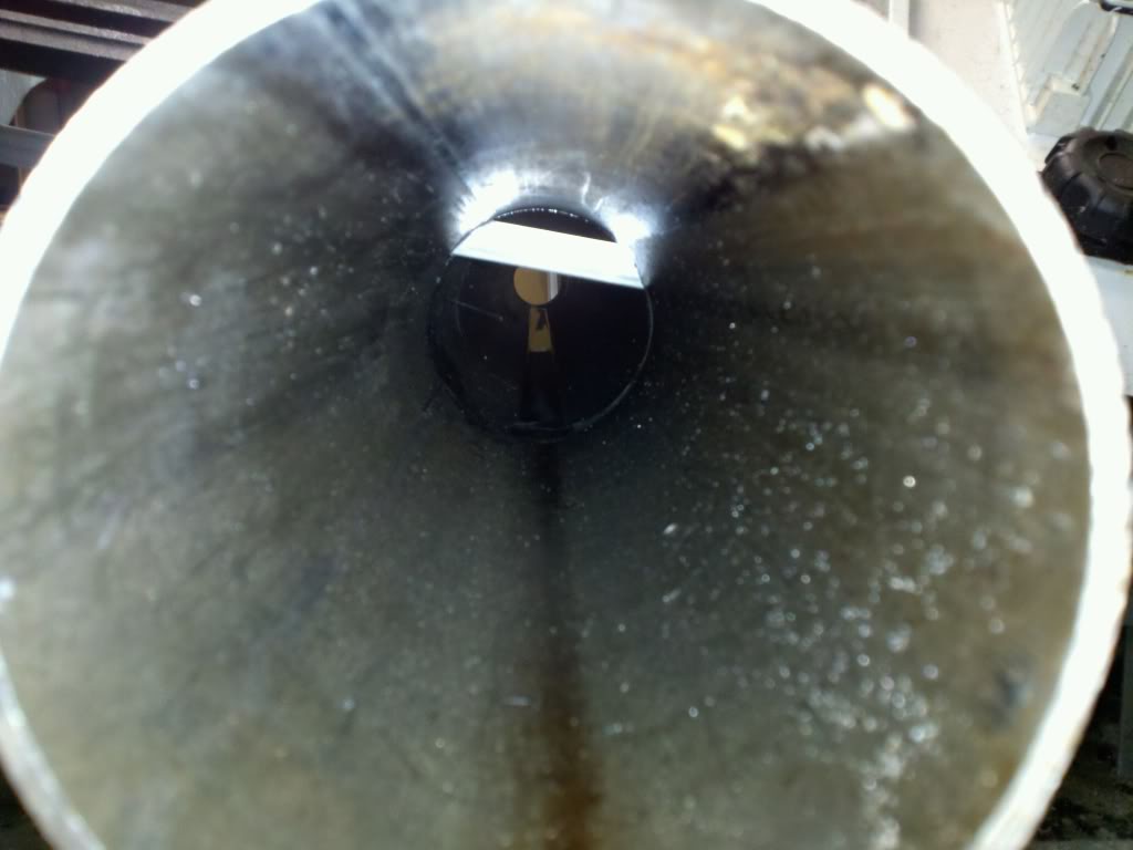
Let the games begin!!!!!!!!!!!!11
Let the games begin!!!!!!!!!!!!11
Reply
0
0


Ok so I have got a lot of work done in the last few days. I am still undecided on weather to run the throttle body in the middle of the intake like stock for ease of piping or to run it out front like a normal car and deal with the crazy piping. I believe I can make my IAC fit onto anything I want when I make an adapter and then I will have the choice to run what ever throttle body I want to so I would like something like a 80mm but I am still unsure.
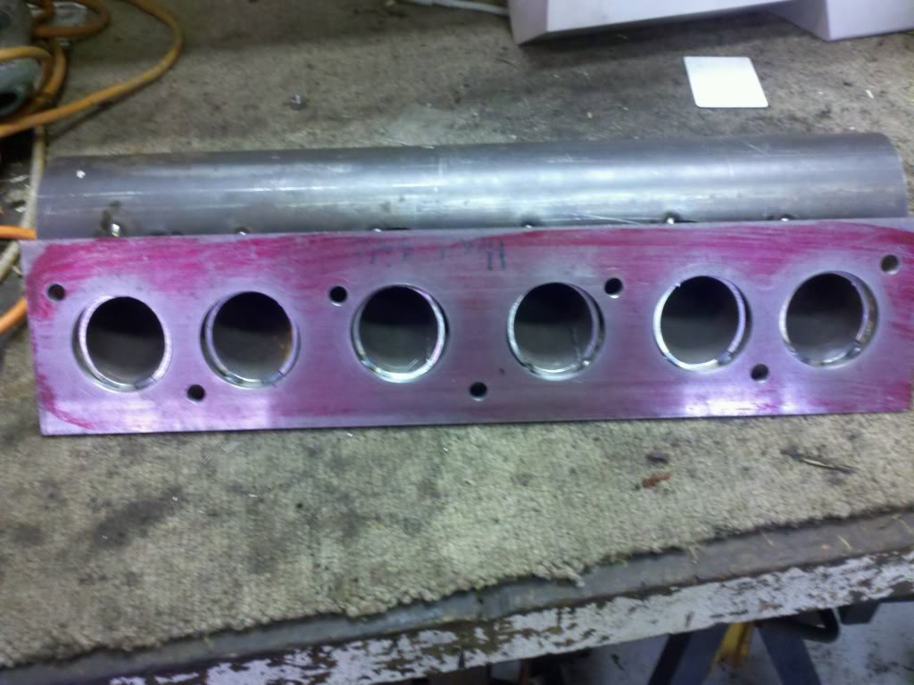
Here are the pics of my intake build I am not done yet but I just finished the mock up stage.
Intake flange
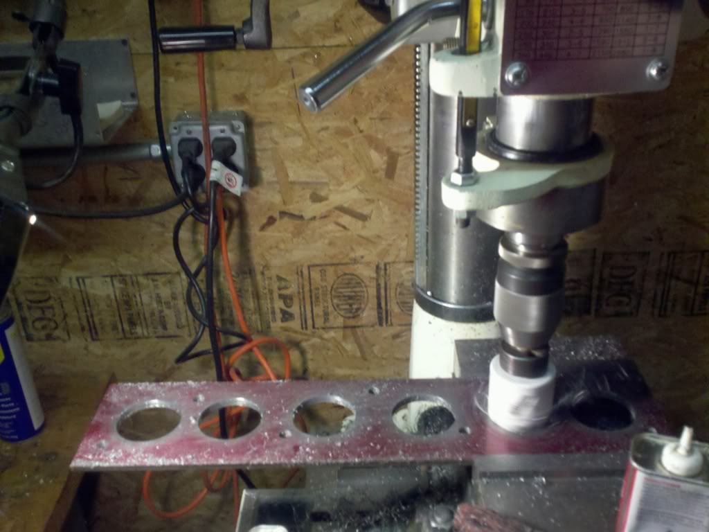
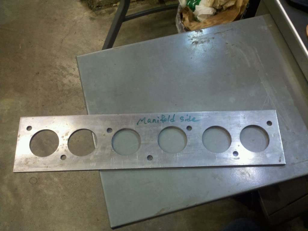
Intake runners in mock up
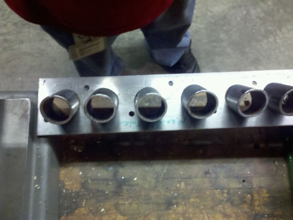
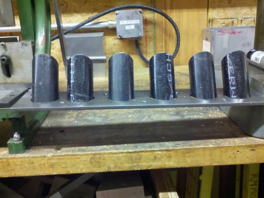
The whole thing getting tacked together
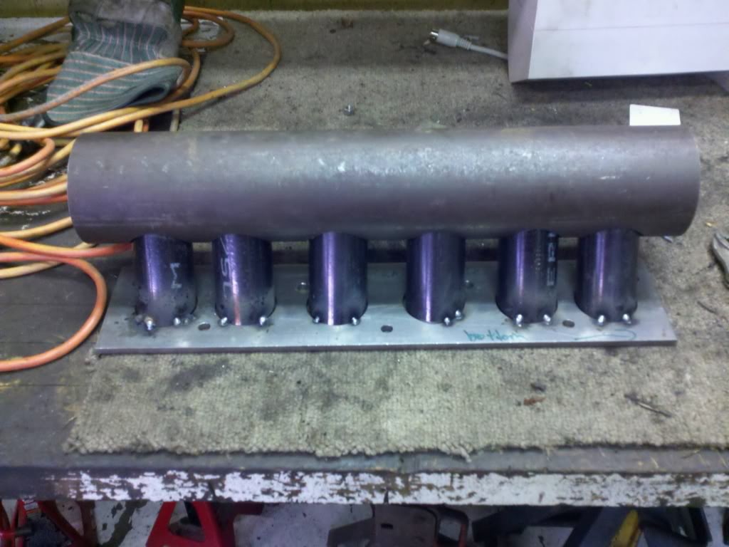
The test fit on the car
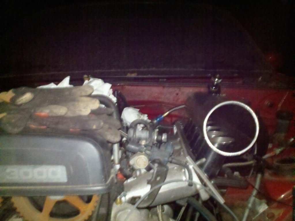
Let me know what you guys think and where do you think I should mount the throttle body. In the middle of the intake facing the valve covers is the easiest way to plumb the system but it looks kinda stupid and I do not want to do all this work for nothing.
Here are the pics of my intake build I am not done yet but I just finished the mock up stage.
Intake flange
Intake runners in mock up
The whole thing getting tacked together
The test fit on the car
Let me know what you guys think and where do you think I should mount the throttle body. In the middle of the intake facing the valve covers is the easiest way to plumb the system but it looks kinda stupid and I do not want to do all this work for nothing.
Reply
0
0
Ok I just ordered my godspeed 90mm throttle body. I have the q45 tps just need to wire it in. I also need to order my wideband sensor, and some -10 an line. Then I can assemble with out the charge piping and get the car running. Then I will get charge piping. Along with new BOV flange and some other minor things and hopefully I can start to lay some boost!!!!!!
here is a pic of my sweet new throttle body.

here is a pic of my sweet new throttle body.
Reply
0
0

That manifold is pretty close to the booster. Would your engine twist with tq at all or are all the mounts solid? I think the tb should be on the front but that's only because it makes more sense to me that way.
Also digging the vw style rusty cam gears
Also digging the vw style rusty cam gears
Reply
0
0
Yea the manifold is close to the booster that is why I put the slash cut at the back of it and as far as the throttle body goes I went front facing because I thought it would look best. The motor does not move at all so I am not worried about it hitting anything now. The motor mounts are solid and I mean steel box tube on steel box tube.lol As far as the rusty cam gears that will come off as soon as the car gets running again.
Reply
0
0


