Ace's Dual Duty LS1 Build
 12-04-2016, 11:32 PM
#21
Elite Member

Join Date: Sep 2015
Location: Seattle, WA
Posts: 1,651
Total Cats: 884
The kooks are such nice headers, so much better than the shorties that plagued v8 miatas for years. Make sure to test fit the passenger side with the engine in cause they come pretty close to the shelf. I notched mine a little bit just to be sure. Making good progress man.

Reply
 0
0

0
12-04-2016, 11:34 PM
#22
Senior Member
Thread Starter
iTrader: (1)

Join Date: Dec 2010
Location: Farmington Hills, MI
Posts: 1,218
Total Cats: 175
The kooks are such nice headers, so much better than the shorties that plagued v8 miatas for years. Make sure to test fit the passenger side with the engine in cause they come pretty close to the shelf. I notched mine a little bit just to be sure. Making good progress man.
Reply
0
0
12-05-2016, 12:40 AM
#23
Senior Member

Join Date: Jul 2014
Location: Milwaukee, WI
Posts: 1,136
Total Cats: 554
Does Tunerstudio have a decent base map to work from on the LSx stuff? I'd imagine so seeing as they are so popular....
I had an MS2 on my turbo NA6.. I'm quite familiar with MS and HPT.. Trying to decide which is better for what I want.. I feel the MS3pro has more capability and adjustments so for the money I may choose the same route as you with my v8 ambitions. Any place in particular you ordered from?
I had an MS2 on my turbo NA6.. I'm quite familiar with MS and HPT.. Trying to decide which is better for what I want.. I feel the MS3pro has more capability and adjustments so for the money I may choose the same route as you with my v8 ambitions. Any place in particular you ordered from?
Reply
0
0
12-05-2016, 08:44 AM
#24
Senior Member
Thread Starter
iTrader: (1)
Join Date: Dec 2010
Location: Farmington Hills, MI
Posts: 1,218
Total Cats: 175
Diyautotune has a base map for both a stock 4.8L truck motor, and a cammed LS1. Sloppy Mechanics has quite a few maps as well.
I ordered directly from Diyautotune, they have always been good to me from a support standpoint, so I gave them my business. Or if my current deal falls through, I've got a second MS3pro for sale haha.
I used MS2 on my BP for a while, and it did what I need it to, but MS3 is even miles better. I'm sure with the basemaps available, and the amount of support around it won't be hard to get a good tune done.
I'll have to give you a ride when it's done. I'm in Milwaukee every now and then since my Dad lives there. I usually drive the Miata to Road America for the IMSA race, and spend the Saturday of that weekend in Milwaukee doing brewery tours.
Reply
0
0
12-06-2016, 12:03 AM
#26
Senior Member
Join Date: Jul 2014
Location: Milwaukee, WI
Posts: 1,136
Total Cats: 554
Diyautotune has a base map for both a stock 4.8L truck motor, and a cammed LS1. Sloppy Mechanics has quite a few maps as well.
I ordered directly from Diyautotune, they have always been good to me from a support standpoint, so I gave them my business. Or if my current deal falls through, I've got a second MS3pro for sale haha.
I used MS2 on my BP for a while, and it did what I need it to, but MS3 is even miles better. I'm sure with the basemaps available, and the amount of support around it won't be hard to get a good tune done.
I'll have to give you a ride when it's done. I'm in Milwaukee every now and then since my Dad lives there. I usually drive the Miata to Road America for the IMSA race, and spend the Saturday of that weekend in Milwaukee doing brewery tours.
I ordered directly from Diyautotune, they have always been good to me from a support standpoint, so I gave them my business. Or if my current deal falls through, I've got a second MS3pro for sale haha.
I used MS2 on my BP for a while, and it did what I need it to, but MS3 is even miles better. I'm sure with the basemaps available, and the amount of support around it won't be hard to get a good tune done.
I'll have to give you a ride when it's done. I'm in Milwaukee every now and then since my Dad lives there. I usually drive the Miata to Road America for the IMSA race, and spend the Saturday of that weekend in Milwaukee doing brewery tours.
And yeah, let me know whenever you make it to the Milwaukee area. any rough timeline on when you're thinking you'll have it done?
Reply
0
0
12-06-2016, 08:41 AM
#27
Senior Member
Thread Starter
iTrader: (1)
Join Date: Dec 2010
Location: Farmington Hills, MI
Posts: 1,218
Total Cats: 175
Good to know. I'll keep a tab on this build to see how the MS3pro works out for you. I like the added features, but the OEM LSx ECU is a pretty capable setup as well fwiw with a large amount of aftermarket support for issue diagnosis and basemaps on the HPT forum. basically if you can do MS or HPT, picking up on the other isnt too hard.
And yeah, let me know whenever you make it to the Milwaukee area. any rough timeline on when you're thinking you'll have it done?
And yeah, let me know whenever you make it to the Milwaukee area. any rough timeline on when you're thinking you'll have it done?
Reply
0
0
12-06-2016, 11:43 AM
#28

if you need any help or have questions just post it up. also we have a V8miatas Facebook group that has some very respected builders. https://www.facebook.com/groups/1618871215007657/
I personally have built the car 2-3 times by now and knows what works and what is to be avoided.
__________________
OG Racing
Your Source For Motorsports Safety Equipment
WWW.OGRACING.COM
800.934.9112
703.430.3303
info@ogracing.com
OG Racing
Your Source For Motorsports Safety Equipment
WWW.OGRACING.COM
800.934.9112
703.430.3303
info@ogracing.com
Reply
0
0
12-06-2016, 10:16 PM
#29
Senior Member
Thread Starter
iTrader: (1)
Join Date: Dec 2010
Location: Farmington Hills, MI
Posts: 1,218
Total Cats: 175
Finished up my wiring diagram. I downloaded the wiring diagram for my year, deleted the pages that I'm eliminating from the car, then pasted each diagram in a big photoshop file. Then I erased all wires I didn't need, and rearranged the power circuit, since I'm replacing the stock fuse box with a Bussmann fuse/relay box. Having a full wiring diagram will be super nice when starting wiring, and when trying to modify things in the future. I will then make closer snapshots of each subsystem, label all connections that go off the page, and print them out to make a wiring book for the car. You can't see much detail from this picture, I may post the detailed pictures if I clean up the diagram a little.
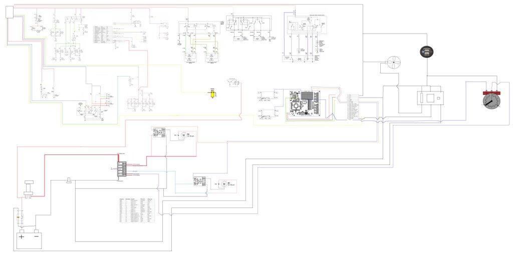
Wiring Diagram Screen Cap by Adam Watson, on Flickr
Wiring Diagram Screen Cap by Adam Watson, on Flickr
Reply
0
0
01-14-2017, 05:02 PM
#30
Senior Member
Thread Starter
iTrader: (1)
Join Date: Dec 2010
Location: Farmington Hills, MI
Posts: 1,218
Total Cats: 175
I've been way too busy to get any real progress done. It's also hard to have the motivation to work out in the cold.. Just sharing a little adapter I made today. I'm starting to get the clutch setup together, and with that I needed a small diameter throw-out bearing. This is an AP Racing TOB. I never thought I'd have AP Racing parts on my car, but it's nice to have the hookup at work for nice parts!
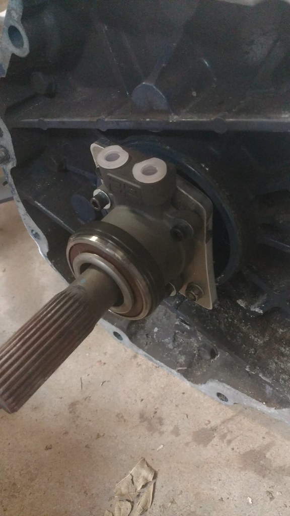
IMG_20170114_154343520 by Adam Watson, on Flickr
IMG_20170114_154343520 by Adam Watson, on Flickr
Reply
1
1
 01-17-2017, 07:34 PM
#34
Senior Member
Thread Starter
iTrader: (1)
Join Date: Dec 2010
Location: Farmington Hills, MI
Posts: 1,218
Total Cats: 175
Yeah it'll come in handy. When wiring in my wideband and MS3x in it was annoying forgetting powering something like the JBPerf Dual VR board, and having to splice it in. This way I have all my components down and can plan for them. It's also a necessity when redoing all power distribution and switches, to know how current flows. Makes it a lot easier to visualize what gauge wire to use, and where switches/relays need to be.
Reply
0
0
01-24-2017, 09:46 PM
#35
Senior Member
Thread Starter
iTrader: (1)
Join Date: Dec 2010
Location: Farmington Hills, MI
Posts: 1,218
Total Cats: 175
Finishing up my ECU/controls box, then I should be full speed ahead with wiring! I'll most likely redo the enclosure on a mill, because my cuts look like crap. Or maybe it doesn't matter that there's gaps everywhere and I can just jam some caulk in it (haha). I flange mounted the MS3pro on the lid so I had a lot of packaging space underneath.
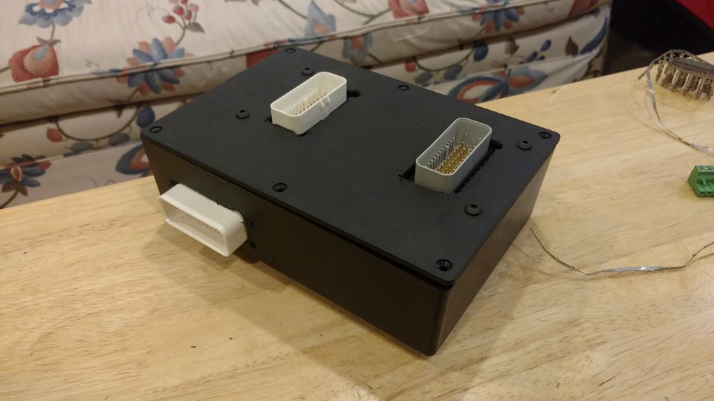
IMG_20170124_211246500 by Adam Watson, on Flickr
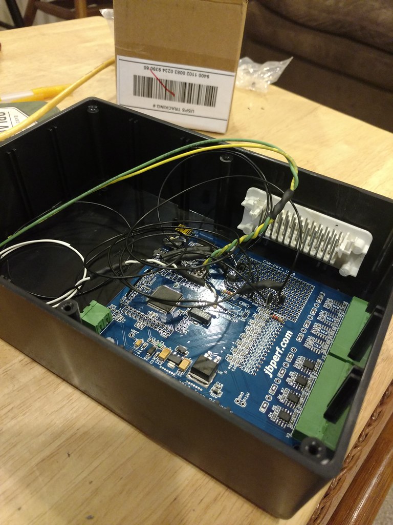
Mounted on the bottom (blue board) is a JBPerf CAN-EGT+. This is a spin-off of the I/O Extender, but doesn't have any of the expansion ports populated except for the ADC ports. You can select how many you want populated with EGT conditioning circuits, and how many you want left open for analog inputs (total of 8). I chose 4 EGT and 4 analog inputs. I should say thermocouple inputs rather than EGT, I'll be using two for cylinder 7 and 8 EGT, one for oil temperature, and one for diff temperature. Two or three ADC's will be used for an accelerometer (not sure if I need Z-axis yet), and one will be used for fuel input. I have a 220 ohm resistor pulled up to 5V to create a voltage divider. If I don't use the Z-axis accel, I'm not sure what I will use but I'm sure I'll find something down the road.
All circuits that are not the ADC's will need conditioning, as they are going straight to the CPU pins. I have 3 circuits built. Two of them are transistor circuits to power a solid state relay for PWM control of DC motors. This will be to vary the speed of my cooling fan and fuel pump. It sketches me out a little bit to be running both of those critical components off of an expansion board that talks over CAN bus, so I will have switches that if the PWM signal is lost, I can trigger the solid state relay to ground and have 100% duty cycle. The main reason for PWM'ing these is power consumption. The fuel pump draws 13 amps (DW300) and the cooling fan can draw up to 40 (Ford Taurus fan). If I don't need 4500 CFM of air, then I can vary the speed and also limit current draw. The third circuit is an activate low input. Basically it's circuit protection for a ground input switch. I'll be using this for datalog input, because I ran out of digital inputs on the MS3pro (I've got a lot of controls!).
In this picture, the green connectors on the right side are the ADC inputs, and the rest is pretty impossible to see what's going on from this picture. The white connector above the CAN-EGT+ is an Ampseal connector that's really intended for mounting to an ECU, but I am using it as a bulkhead connector. This will be used to pass signals and power from the widebands and CAN-EGT+ board to the wiring harness. The wideband controllers will package to the side of the CAN-EGT+. The 14point7 SLC OEM wideband controllers communicate with the CAN-EGT+ over I2C, which is a form of digital communication. This will guarantee no voltage offsets. It's also cheap, $90 with sensor, each.
More info on this board can be found here: jbperf.com ? View topic - CAN-EGT+
This board uses the same CPU as the I/O Extender, so the documentation (that is non existent for the CAN-EGT+) follows this: I/O Extender Board v1.0 for M2/Extra and MS3
Just note that the only things that come out of the box are ADC's, I2C, CAN, and serial comm (for Innovate wideband), and anything else that the I/O Extender is capable of will need conditioning.
2017-01-24_09-16-15 by Adam Watson, on Flickr
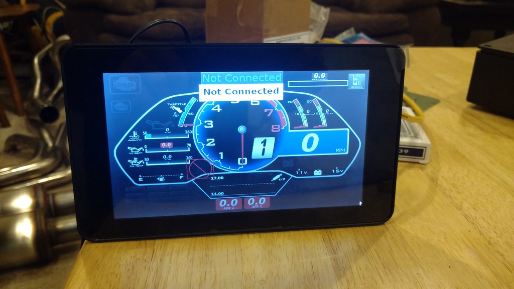
Finally, I've got my Raspberry Pi 3 assembled and ready to mount. I bought a dash off of Welcome to Tuner Studio Dashboards! - TunerStudio Dashboards. I'll be powering it from a 3A 12V-5V regulator. I'll be managing shut down using a switch that sends a signal to a GPIO pin to command shutdown. I replaced my Racepak with this, for unlimited customization of the dash and tuning on the fly.
IMG_20170124_211428621 by Adam Watson, on Flickr
IMG_20170124_211246500 by Adam Watson, on Flickr
Mounted on the bottom (blue board) is a JBPerf CAN-EGT+. This is a spin-off of the I/O Extender, but doesn't have any of the expansion ports populated except for the ADC ports. You can select how many you want populated with EGT conditioning circuits, and how many you want left open for analog inputs (total of 8). I chose 4 EGT and 4 analog inputs. I should say thermocouple inputs rather than EGT, I'll be using two for cylinder 7 and 8 EGT, one for oil temperature, and one for diff temperature. Two or three ADC's will be used for an accelerometer (not sure if I need Z-axis yet), and one will be used for fuel input. I have a 220 ohm resistor pulled up to 5V to create a voltage divider. If I don't use the Z-axis accel, I'm not sure what I will use but I'm sure I'll find something down the road.
All circuits that are not the ADC's will need conditioning, as they are going straight to the CPU pins. I have 3 circuits built. Two of them are transistor circuits to power a solid state relay for PWM control of DC motors. This will be to vary the speed of my cooling fan and fuel pump. It sketches me out a little bit to be running both of those critical components off of an expansion board that talks over CAN bus, so I will have switches that if the PWM signal is lost, I can trigger the solid state relay to ground and have 100% duty cycle. The main reason for PWM'ing these is power consumption. The fuel pump draws 13 amps (DW300) and the cooling fan can draw up to 40 (Ford Taurus fan). If I don't need 4500 CFM of air, then I can vary the speed and also limit current draw. The third circuit is an activate low input. Basically it's circuit protection for a ground input switch. I'll be using this for datalog input, because I ran out of digital inputs on the MS3pro (I've got a lot of controls!).
In this picture, the green connectors on the right side are the ADC inputs, and the rest is pretty impossible to see what's going on from this picture. The white connector above the CAN-EGT+ is an Ampseal connector that's really intended for mounting to an ECU, but I am using it as a bulkhead connector. This will be used to pass signals and power from the widebands and CAN-EGT+ board to the wiring harness. The wideband controllers will package to the side of the CAN-EGT+. The 14point7 SLC OEM wideband controllers communicate with the CAN-EGT+ over I2C, which is a form of digital communication. This will guarantee no voltage offsets. It's also cheap, $90 with sensor, each.
More info on this board can be found here: jbperf.com ? View topic - CAN-EGT+
This board uses the same CPU as the I/O Extender, so the documentation (that is non existent for the CAN-EGT+) follows this: I/O Extender Board v1.0 for M2/Extra and MS3
Just note that the only things that come out of the box are ADC's, I2C, CAN, and serial comm (for Innovate wideband), and anything else that the I/O Extender is capable of will need conditioning.
2017-01-24_09-16-15 by Adam Watson, on Flickr
Finally, I've got my Raspberry Pi 3 assembled and ready to mount. I bought a dash off of Welcome to Tuner Studio Dashboards! - TunerStudio Dashboards. I'll be powering it from a 3A 12V-5V regulator. I'll be managing shut down using a switch that sends a signal to a GPIO pin to command shutdown. I replaced my Racepak with this, for unlimited customization of the dash and tuning on the fly.
IMG_20170124_211428621 by Adam Watson, on Flickr
Reply
0
0
01-25-2017, 08:51 AM
#36
Junior Member

Join Date: Mar 2011
Location: Melbourne, Australia
Posts: 212
Total Cats: 67
Hey nice work with the raspi dash 
Love to hear how the DASH is working for you and if you've had any issues or changed it in any way from the 'stock' one straight for the site?
I don't suppose you've got it hooked up to the ecu yet? Did it handle the different firmware OK?
Love to hear how the DASH is working for you and if you've had any issues or changed it in any way from the 'stock' one straight for the site?
I don't suppose you've got it hooked up to the ecu yet? Did it handle the different firmware OK?
Reply
0
0
01-25-2017, 09:06 AM
#37
Senior Member
Thread Starter
iTrader: (1)
Join Date: Dec 2010
Location: Farmington Hills, MI
Posts: 1,218
Total Cats: 175
So far I like the dash, but haven't hooked up to an ECU yet! Should get that soon. I uploaded the 1.5 firmware ini file and it seems to be working properly. I changed a few things around. I copied the boost gauge and re-purposed them as EGT gauges, since I'm naturally aspirated. Also changed the units to imperial and added AFR gauges to the bottom, in addition to the line graph. I also copied and pasted the AFR line graph and overlayed it to display AFR2 as well. Do you know if it's possible to change color of the line on the line graph? It doesn't look like the line shows up in the gauge demo mode so it's hard to test. Oh also added the ethanol content gauge in the top right corner.
Reply
0
0
01-25-2017, 09:24 AM
#38
Junior Member
Join Date: Mar 2011
Location: Melbourne, Australia
Posts: 212
Total Cats: 67
It has scaled perfectly for the display you are using which is nice.
Regarding the AFR line graph, from the Color Properties dialog, it is needle color you want to change I am pretty sure... been a while since I lasted tested a line graph so i cant remember exactly.
I could probably re-purpose the fuel level graph as your ethanol content, change the E and F to 0% and 100%? Send me a PM if you want.
Reply
0
0
01-25-2017, 09:29 AM
#39
Senior Member
Thread Starter
iTrader: (1)
Join Date: Dec 2010
Location: Farmington Hills, MI
Posts: 1,218
Total Cats: 175
Thanks I'll check that out tonight.
I will be keeping the fuel level graph, so I don't think there's room for the ethanol content inside the "Lambo" frame.
I will be keeping the fuel level graph, so I don't think there's room for the ethanol content inside the "Lambo" frame.
Reply
0
0
01-25-2017, 07:00 PM
#40
Senior Member
Thread Starter
iTrader: (1)
Join Date: Dec 2010
Location: Farmington Hills, MI
Posts: 1,218
Total Cats: 175
I got my accelerometer working with the JBPerf board. Right now I'm just communicating with the board directly (rather than over CAN through MS3), so I'm only displaying the raw ADC values. I think I can get over 8 ADC's with making a conditioning circuit, so I'll run the 3 axis. I've also decided to add a coolant pressure sensor. This can help detect knock (high cylinder pressure causes a very quick head float pumping pressure to the system), and can save an engine on track. Heads warp when the engine is hot and there is air in the passages, so a blown hose on track could warp the head before the coolant temperature sensor indicates an issue.
Reply
0
0


