
Barton's na6


Thread Starter
Junior Member
Joined: Jun 2015
Posts: 182
Total Cats: 58
From: VIC, Australia
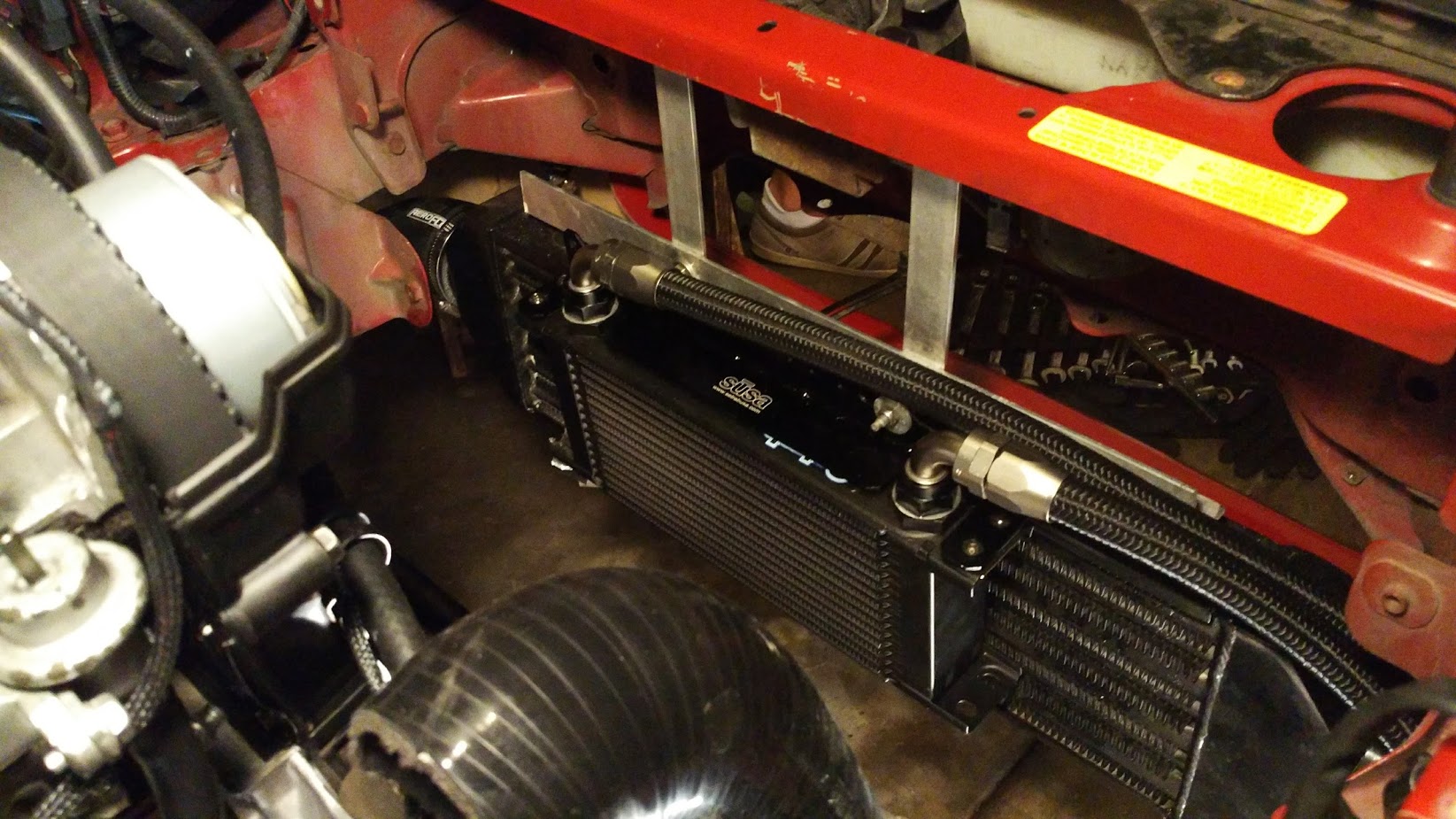
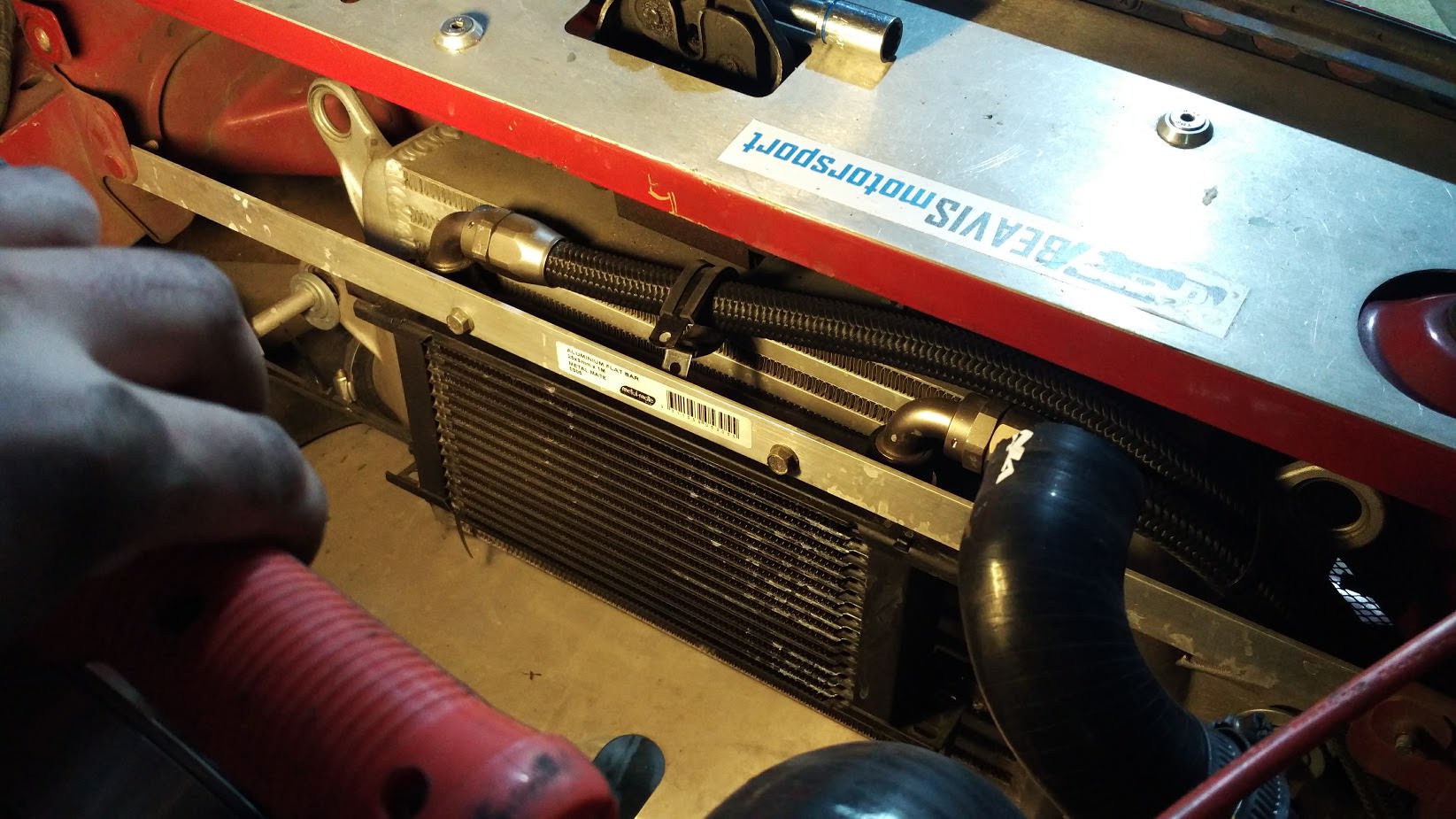
Been a while since I last updated this. Added an oil cooler to keep oil temps down and more consistent at the track. Previously they'd start climbing north of 120 degrees after a few hot laps or so. Not it stays fairly consistent and climbs very slowly from 90-110 during each session. I used Trackspeeds kit which came with really good quality components.
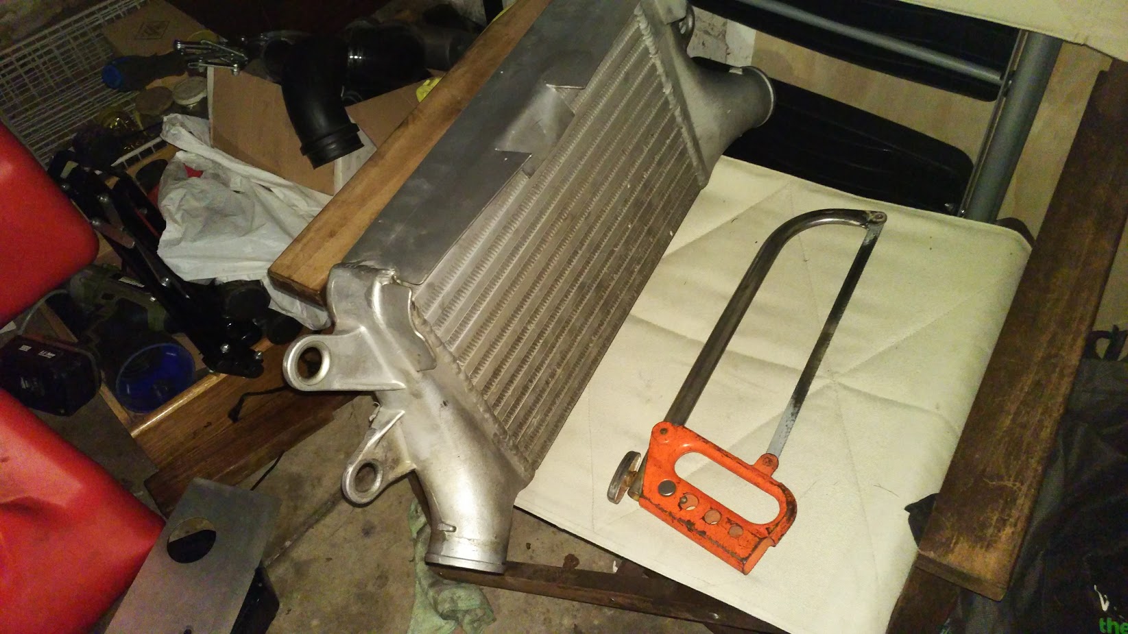
Also stuck in a better intercooler to combat the stupid high air temps I was seeing with the ebay POS unit I had before. Intercooler is from a Ford Falcon XR6 turbo and only cost me 100 dollarydoos. It's got a nice shroud on it too although I had to cut a slot in it to fit with the bonnet latch support. The bolt holes almost line up with the A/C condenser brackets which was handy. Only had to make some real small metal tabs to get it mounted up.
Also stuck in a better intercooler to combat the stupid high air temps I was seeing with the ebay POS unit I had before. Intercooler is from a Ford Falcon XR6 turbo and only cost me 100 dollarydoos. It's got a nice shroud on it too although I had to cut a slot in it to fit with the bonnet latch support. The bolt holes almost line up with the A/C condenser brackets which was handy. Only had to make some real small metal tabs to get it mounted up.
Reply
 0
0

0
Thread Starter
Junior Member
Joined: Jun 2015
Posts: 182
Total Cats: 58
From: VIC, Australia
Got round to setting up and installing my new raspberry pi based digital dash. More details can be found in this thread: https://www.miataturbo.net/megasquir...acedash-92851/
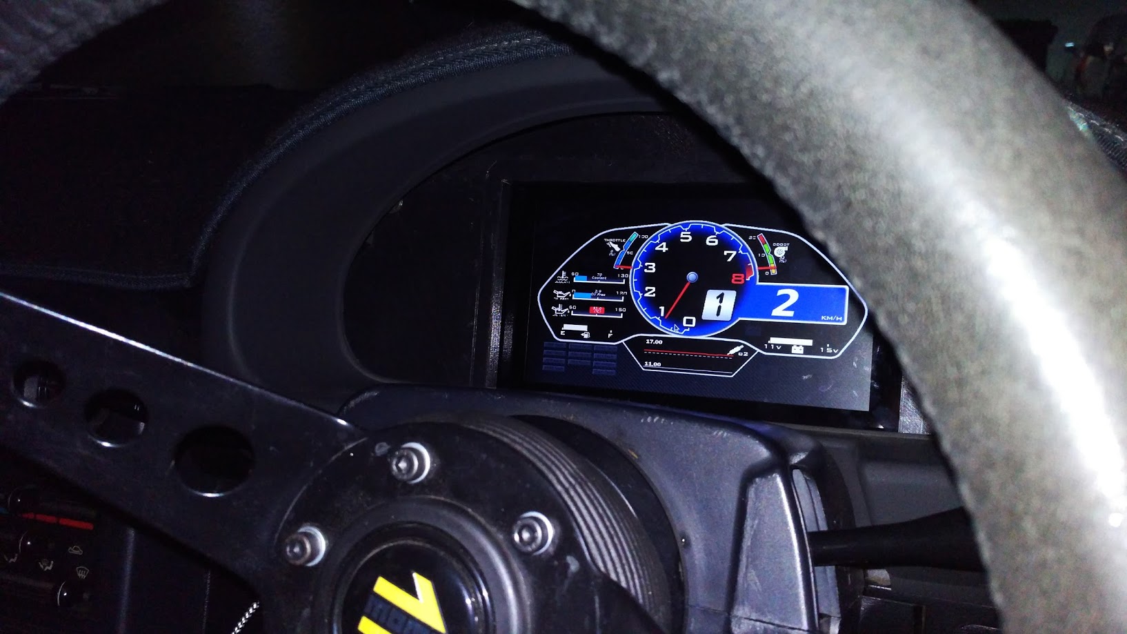
The fuel level input circuit just needs some adjusting when I get some time to pull the ECU but apart from that it works really well. It's nice being able to monitor exactly what I want right in front of me and also being able to adjust tune parameters without having to pull the laptop out.
I also managed to trace down the source of the annoying voltage drop I had on the ECU 12V supply. I went back to my car after parking it an hour earlier and it wouldn't start. Fuel pump wouldn't prime and it didn't seem to be getting any power to the ECU. Ended up being a melted main relay so I added a relay to power the fuel pump taking 12V straight off the battery.
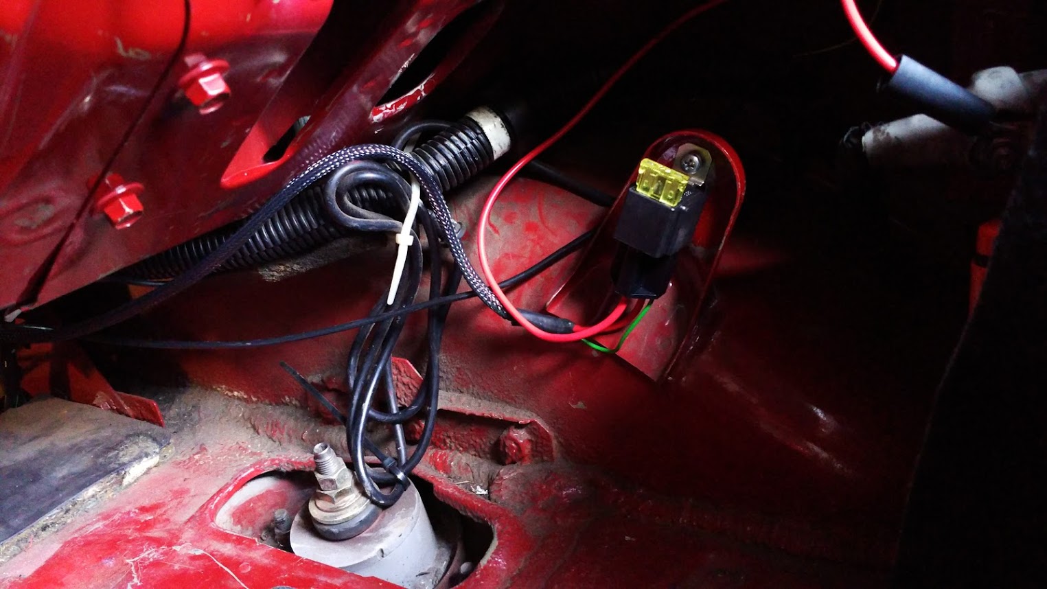
I ended up solving two problems at once as it turns out that the fuel pump was the cause of the large voltage drop I was getting at the ECU due to it's large current draw and being on the same circuit as the ECU. So now I get within 0.1-0.2V difference between the ECU voltage supply level at the alternator output which is great. I also won't have any more main relay failures.
The fuel level input circuit just needs some adjusting when I get some time to pull the ECU but apart from that it works really well. It's nice being able to monitor exactly what I want right in front of me and also being able to adjust tune parameters without having to pull the laptop out.
I also managed to trace down the source of the annoying voltage drop I had on the ECU 12V supply. I went back to my car after parking it an hour earlier and it wouldn't start. Fuel pump wouldn't prime and it didn't seem to be getting any power to the ECU. Ended up being a melted main relay so I added a relay to power the fuel pump taking 12V straight off the battery.
I ended up solving two problems at once as it turns out that the fuel pump was the cause of the large voltage drop I was getting at the ECU due to it's large current draw and being on the same circuit as the ECU. So now I get within 0.1-0.2V difference between the ECU voltage supply level at the alternator output which is great. I also won't have any more main relay failures.
Reply
0
0

Thread Starter
Junior Member
Joined: Jun 2015
Posts: 182
Total Cats: 58
From: VIC, Australia
Small update. Not much time to work on the car unfortunately and having to get it back together to drive to work the next day makes it hard to do things on weekdays. A second car would be handy.
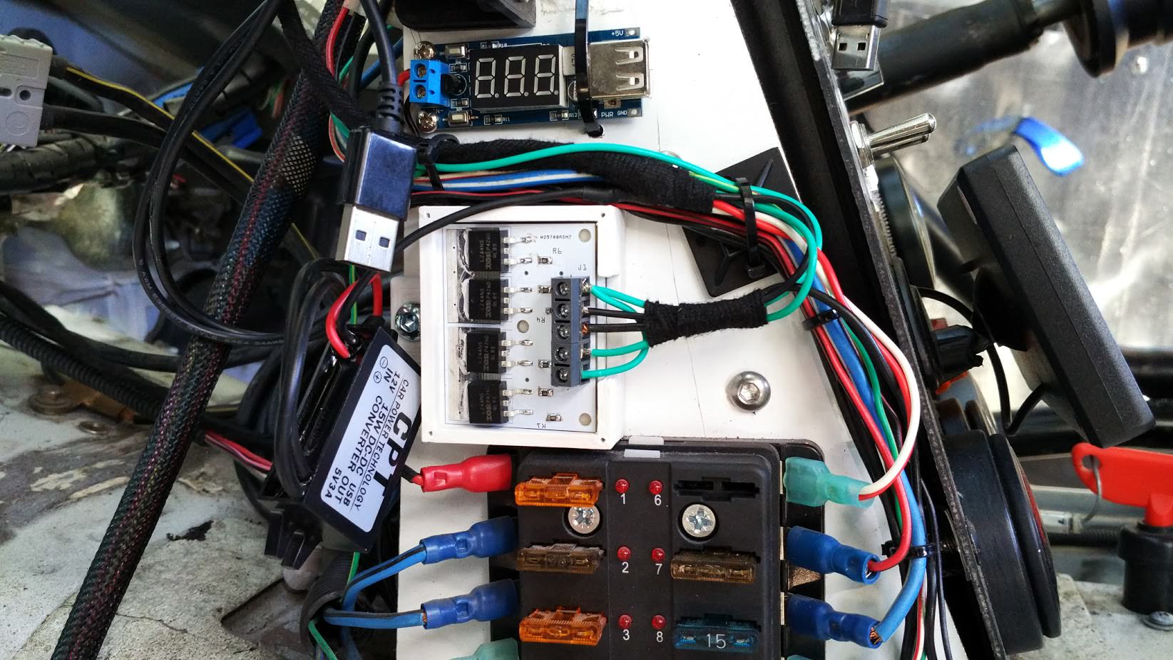
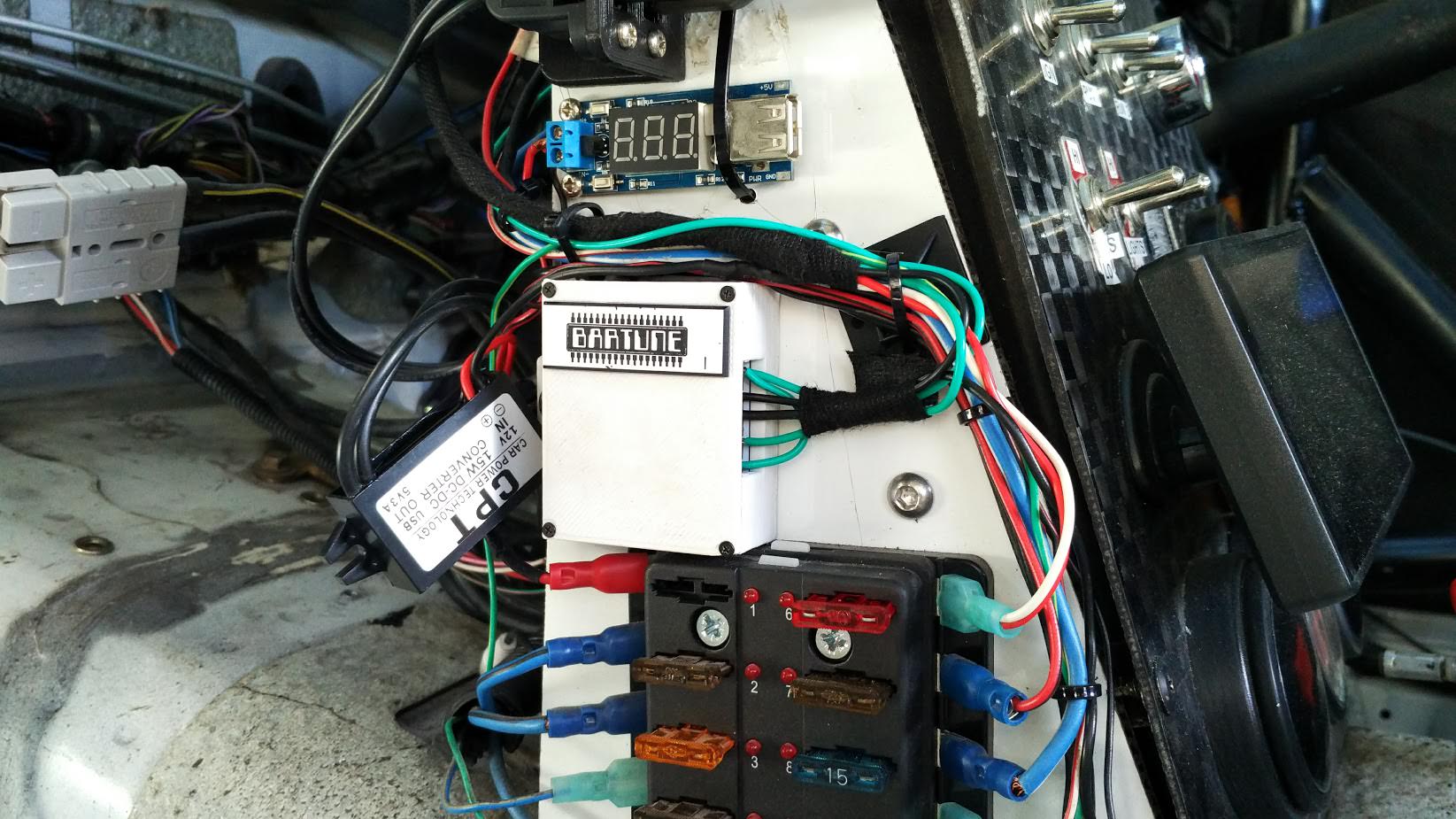
First up I installed the solid state relay board I designed although not in my own car. Went in Beavis' track car to control the new electric water pump. Seems to work well varying the speed and the board temperature stays quite low. Also set up close-loop control for it too although will most likely need tweaking once the car gets moving and actually sees some airflow.
Next was a new crossflow radiator from 949. Seems to be working very well in this hot weather with coolant temps constantly sitting around the thermostat opening point. Will be able to test it on the track soon and see how it goes. Also revised my oil cooler mounting while I was there.
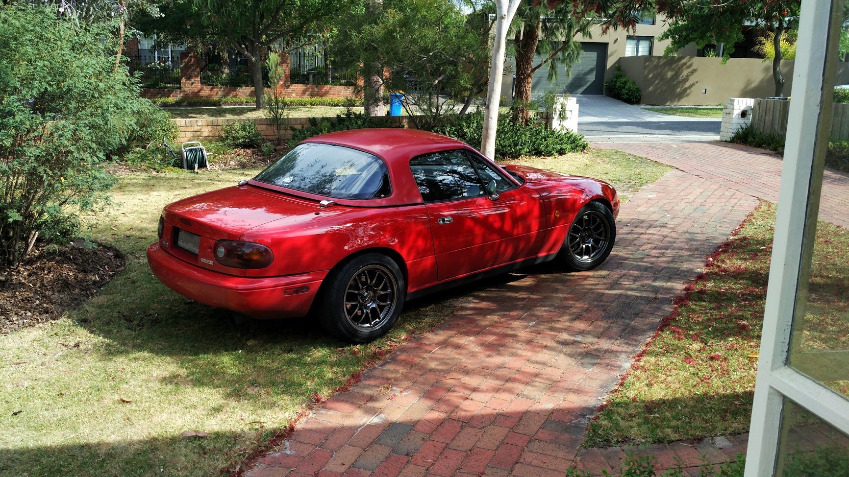
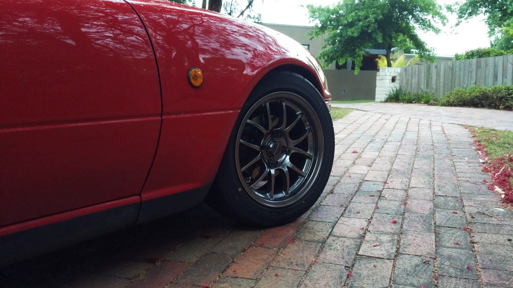
And lastly a new set of 6UL wheels with some brand new ad08r tyres.
First up I installed the solid state relay board I designed although not in my own car. Went in Beavis' track car to control the new electric water pump. Seems to work well varying the speed and the board temperature stays quite low. Also set up close-loop control for it too although will most likely need tweaking once the car gets moving and actually sees some airflow.
Next was a new crossflow radiator from 949. Seems to be working very well in this hot weather with coolant temps constantly sitting around the thermostat opening point. Will be able to test it on the track soon and see how it goes. Also revised my oil cooler mounting while I was there.
And lastly a new set of 6UL wheels with some brand new ad08r tyres.
Reply
0
0

Thread Starter
Junior Member
Joined: Jun 2015
Posts: 182
Total Cats: 58
From: VIC, Australia
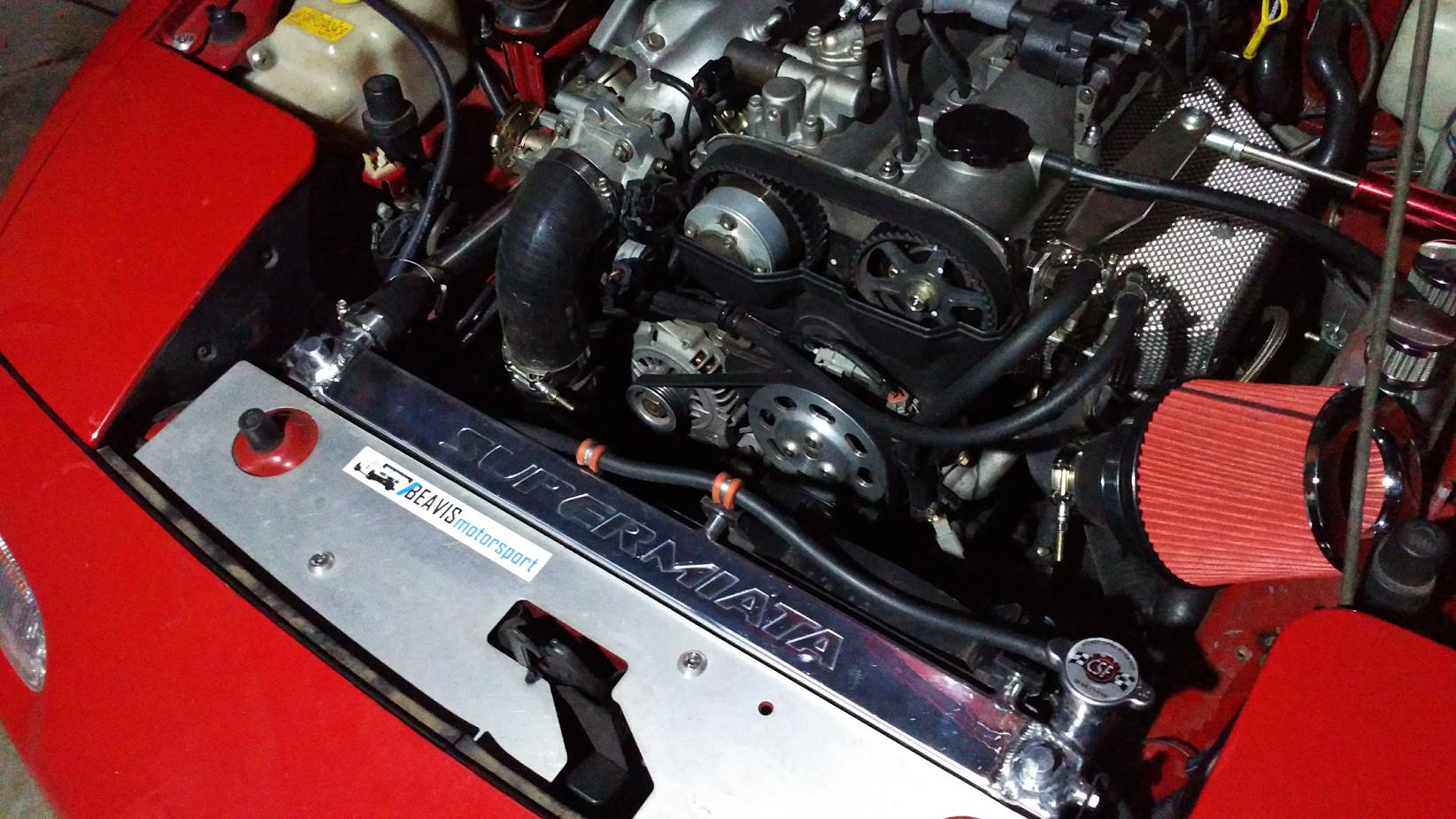
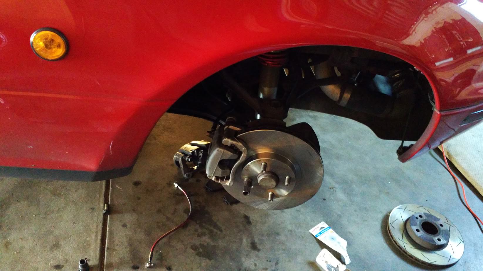
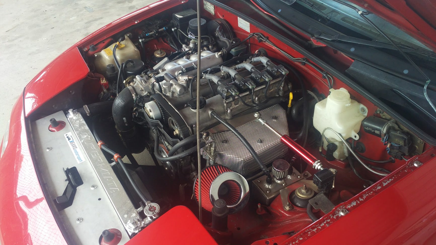
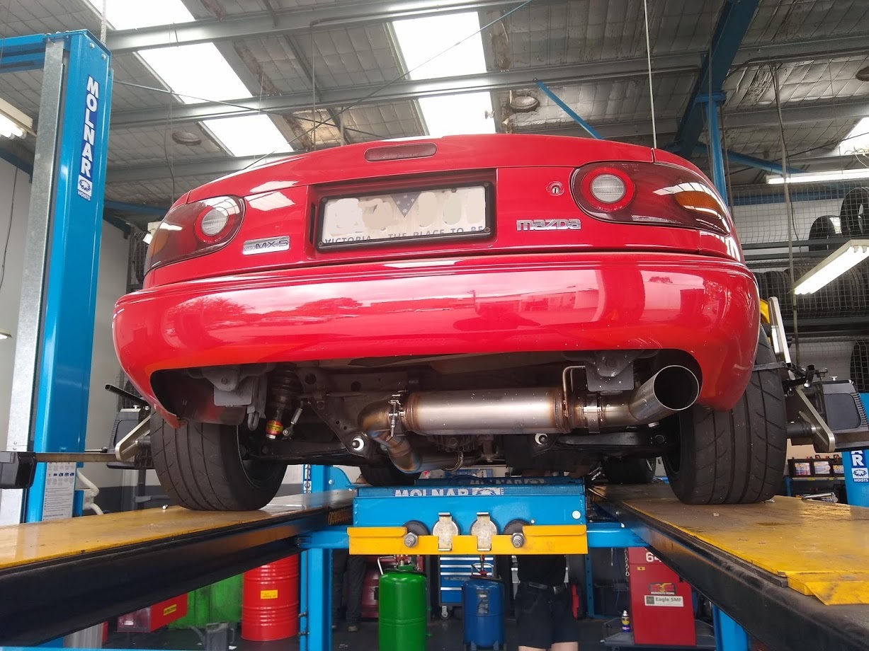
Upgraded to some larger brakes from an SE (MSM) which worked wonderfully at the track. No more brake fade after a couple of laps. The supermiata cross-flow radiator worked very well too with coolant temps hitting 100deg C peak with ambient temperature around 35+ deg C. Took another few seconds off my PB even with a lot of traffic and high temperatures.
Bonus engine bay shot.
Video of fastest lap. Video quality is pretty crap. Need to play around with the camera settings to adjust lighting.
Bonus engine bay shot.
Video of fastest lap. Video quality is pretty crap. Need to play around with the camera settings to adjust lighting.
Reply
0
0
Senior Member

Joined: Apr 2016
Posts: 790
Total Cats: 188
From: Atlanta
This has to be one of the cleanest builds I've seen here... really nice work.
What pads are you running in the NB2 brakes? I've got the parts sitting around to do the conversion, just haven't gotten to it yet.
What pads are you running in the NB2 brakes? I've got the parts sitting around to do the conversion, just haven't gotten to it yet.
Reply
0
0
Thread Starter
Junior Member
Joined: Jun 2015
Posts: 182
Total Cats: 58
From: VIC, Australia
Sold off all my turbo bits and bought a Kraken kit to replace it with. Also picked up a flat top manifold to replace the VICS one.
The car feels quite slow being n/a again but shouldn't be too long before it gets boost again. I've also noticed the stock airbox is quite restrictive only allowing me to reach ~95kpa.
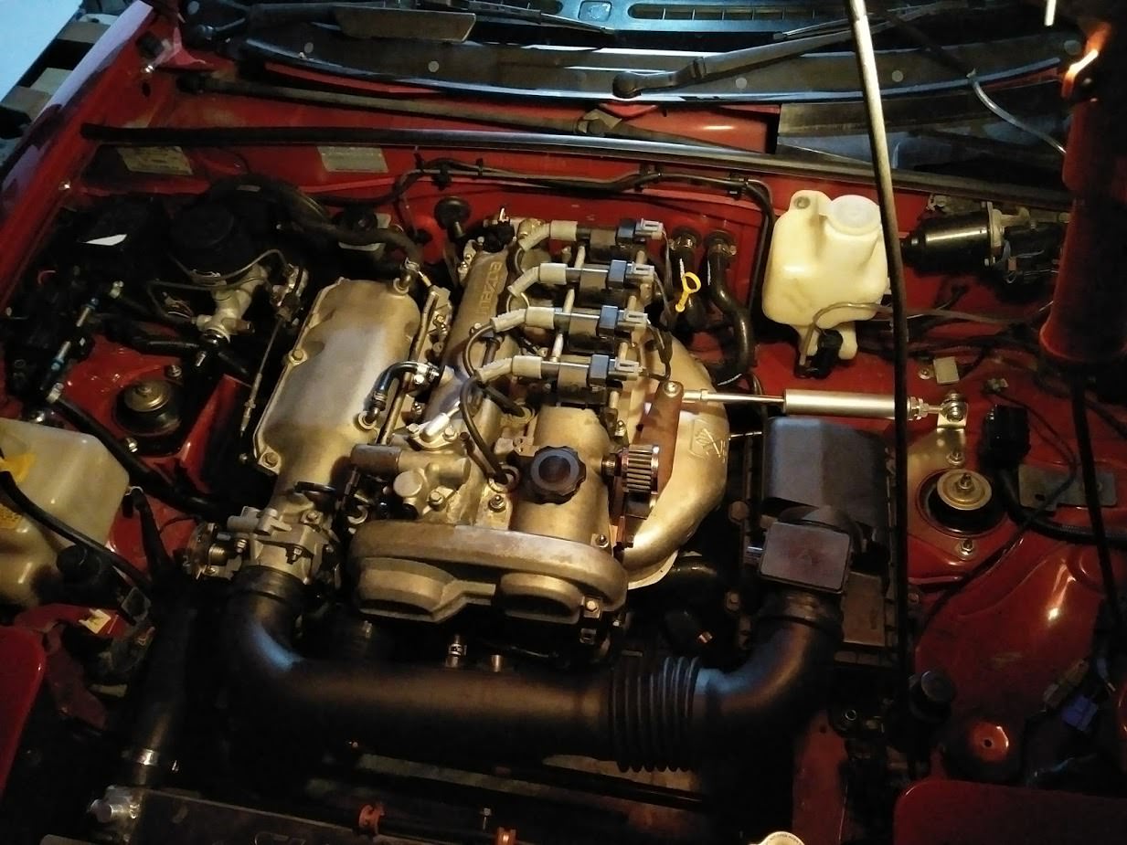
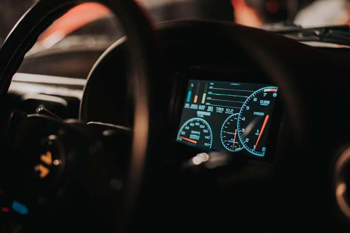
Also created a nice gauge cluster based off one I found a while ago.
The car feels quite slow being n/a again but shouldn't be too long before it gets boost again. I've also noticed the stock airbox is quite restrictive only allowing me to reach ~95kpa.
Also created a nice gauge cluster based off one I found a while ago.
Reply
0
0

Joined: Aug 2014
Posts: 1,462
Total Cats: 389
From: Bainbridge Island, WA
Hey now! You can't leave us hangin' like that! Details!

__________________
Reply
0
0
Joined: Aug 2014
Posts: 1,462
Total Cats: 389
From: Bainbridge Island, WA

__________________
Reply
0
0
Joined: Aug 2014
Posts: 1,462
Total Cats: 389
From: Bainbridge Island, WA
Look at that! Everything you need to know in one tidy and beautifully narrated video!
__________________
Reply
0
0
Thread Starter
Junior Member
Joined: Jun 2015
Posts: 182
Total Cats: 58
From: VIC, Australia
I have been very busy with work so only a small update to the MX-5. Have mainly been buying parts and letting them collect dust.
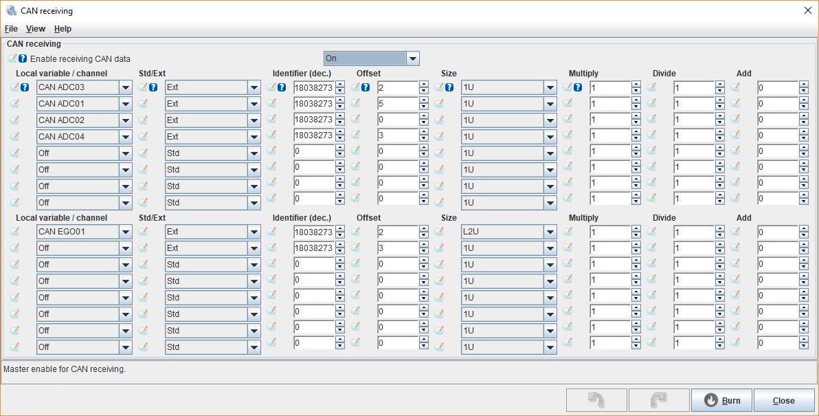
Got myself a refurbished ms3pro 1st gen for quite cheap which I will eventually mount in the engine bay when I re-wire everything. Silver box is an Ecotrons ALM-CAN wideband module which I will also be using. Communicates directly with MS via CAN bus. Since I want to also use other CAN bus devices and the ALM comes default with a 250k baud rate I'll need to re-program it to 500k.
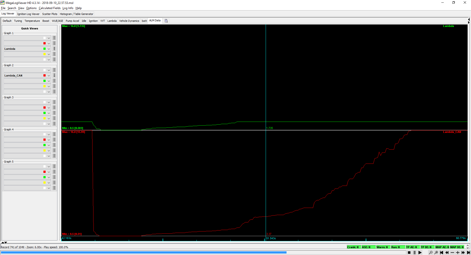
Currently have the MS receiving the messages from it however I've noticed that when using the "Ecotrons ALM" CAN-EGO dropdown input the sensor range is limited to 0.5-1.735 lambda while the actual sensor reading goes from 0.5-15.99 lambda (not that you really need to see values that high).
Also receiving sensor temperature data and it also sends out error codes however I haven't set anything up for that yet.
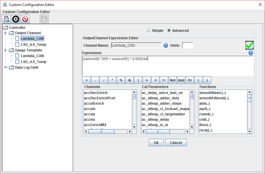
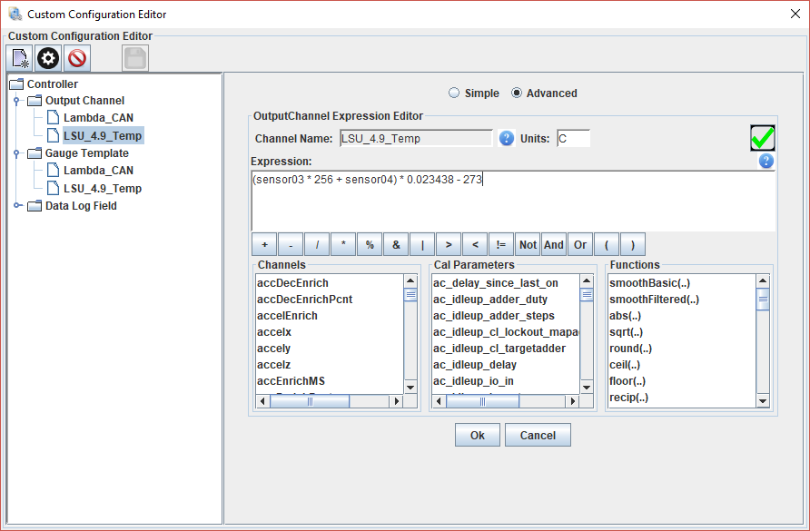
Will also need to look into a better way of inputting the data. Lambda and temperature data are both contained in 2 bytes each. I'm reading each byte individually and putting the raw data into a generic sensor input, and then using the custom channel editor to convert the raw values.
Bench testing:
Lambda readout. Lambda_CAN is the actual data received from the controller. You can see that the CAN-EGO input is capped at 1.735 lambda. I used cigarette lighter gas to displace the oxygen in the sensor tip.
Lambda raw conversion
Temperature raw conversion
CAN Receiving settings:
Got myself a refurbished ms3pro 1st gen for quite cheap which I will eventually mount in the engine bay when I re-wire everything. Silver box is an Ecotrons ALM-CAN wideband module which I will also be using. Communicates directly with MS via CAN bus. Since I want to also use other CAN bus devices and the ALM comes default with a 250k baud rate I'll need to re-program it to 500k.
Currently have the MS receiving the messages from it however I've noticed that when using the "Ecotrons ALM" CAN-EGO dropdown input the sensor range is limited to 0.5-1.735 lambda while the actual sensor reading goes from 0.5-15.99 lambda (not that you really need to see values that high).
Also receiving sensor temperature data and it also sends out error codes however I haven't set anything up for that yet.
Will also need to look into a better way of inputting the data. Lambda and temperature data are both contained in 2 bytes each. I'm reading each byte individually and putting the raw data into a generic sensor input, and then using the custom channel editor to convert the raw values.
Bench testing:
Lambda readout. Lambda_CAN is the actual data received from the controller. You can see that the CAN-EGO input is capped at 1.735 lambda. I used cigarette lighter gas to displace the oxygen in the sensor tip.
Lambda raw conversion
Temperature raw conversion
CAN Receiving settings:
Reply
0
0
Thread Starter
Junior Member
Joined: Jun 2015
Posts: 182
Total Cats: 58
From: VIC, Australia
Wow it's been a year since I updated this.
I haven't really had much time for this car over the last year due to work but a few things have happened.
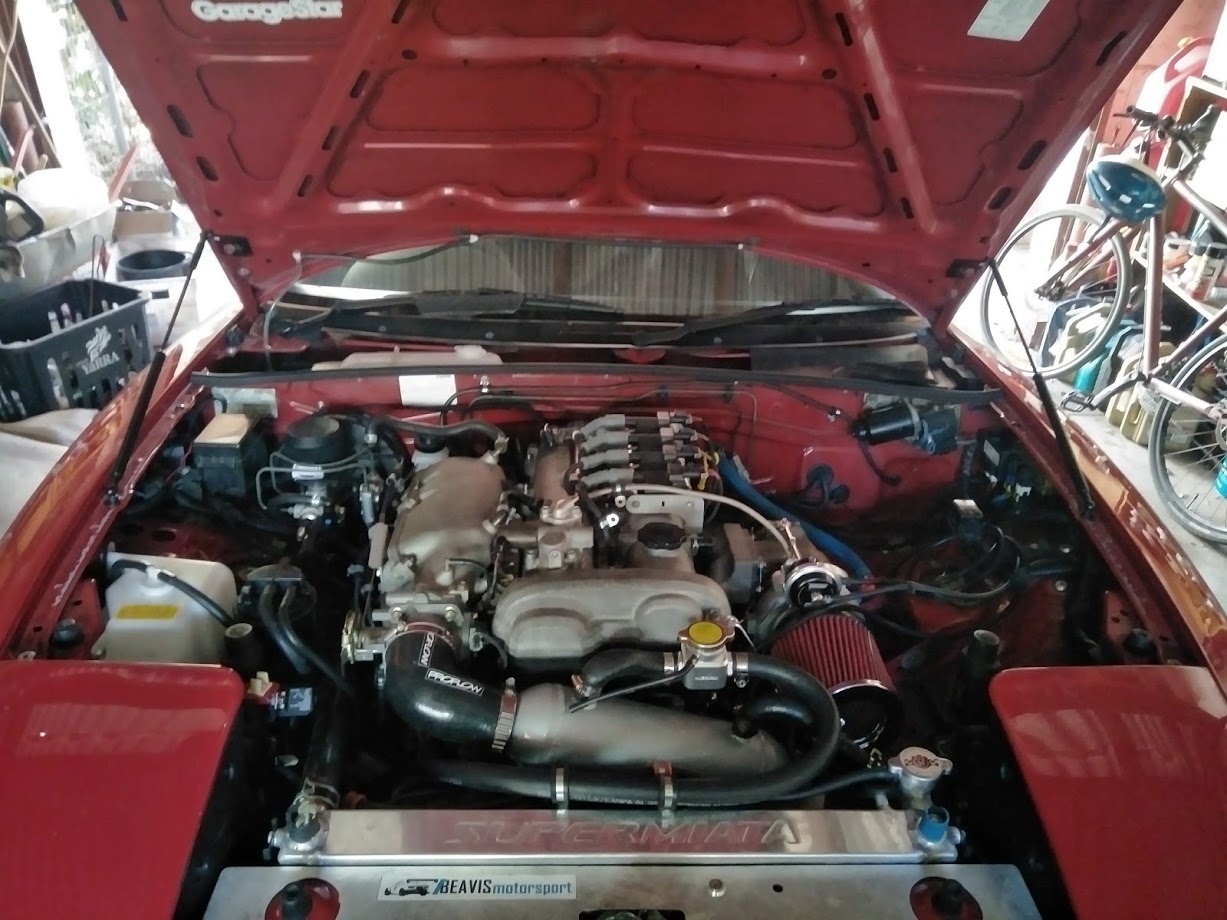
It's turbo again thanks to Kraken!
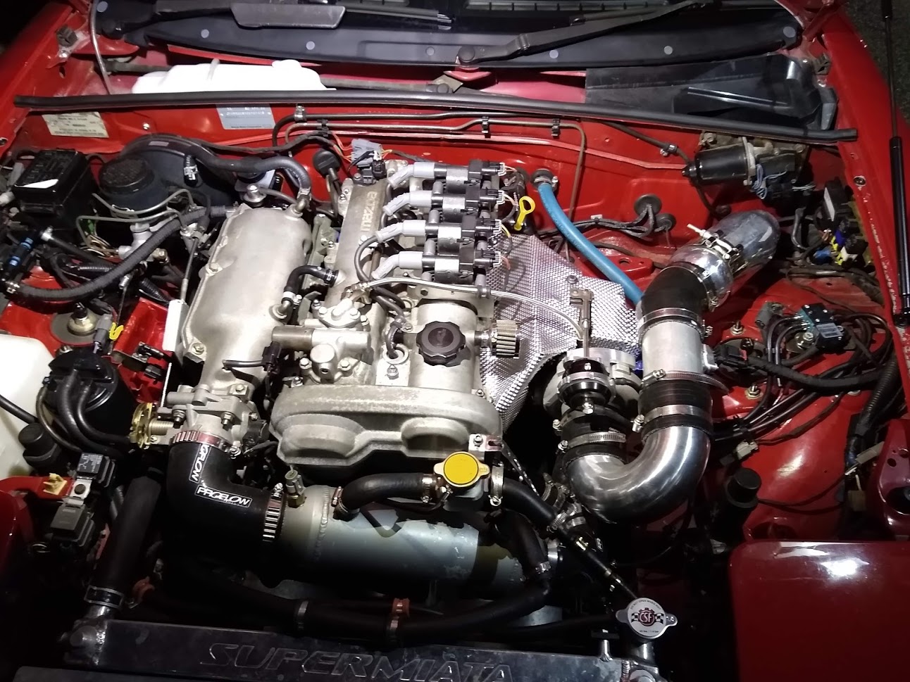
As you can probably work out I've decided to use a water to air intercooler setup this time. Aim is to get the best response possible and keep intake temperatures very consistent. Biggest bonus for me is that I don't have an obvious intercooler visible at the front of the car. A/C condensor is being used as the heat exchanger for the intercooler since it as free and bolts straight up. Possibly not the best choice but so far it seems to be holding up well enough. Worst case I can swap back to using an air to air setup with the xr6 intercooler I used previously.
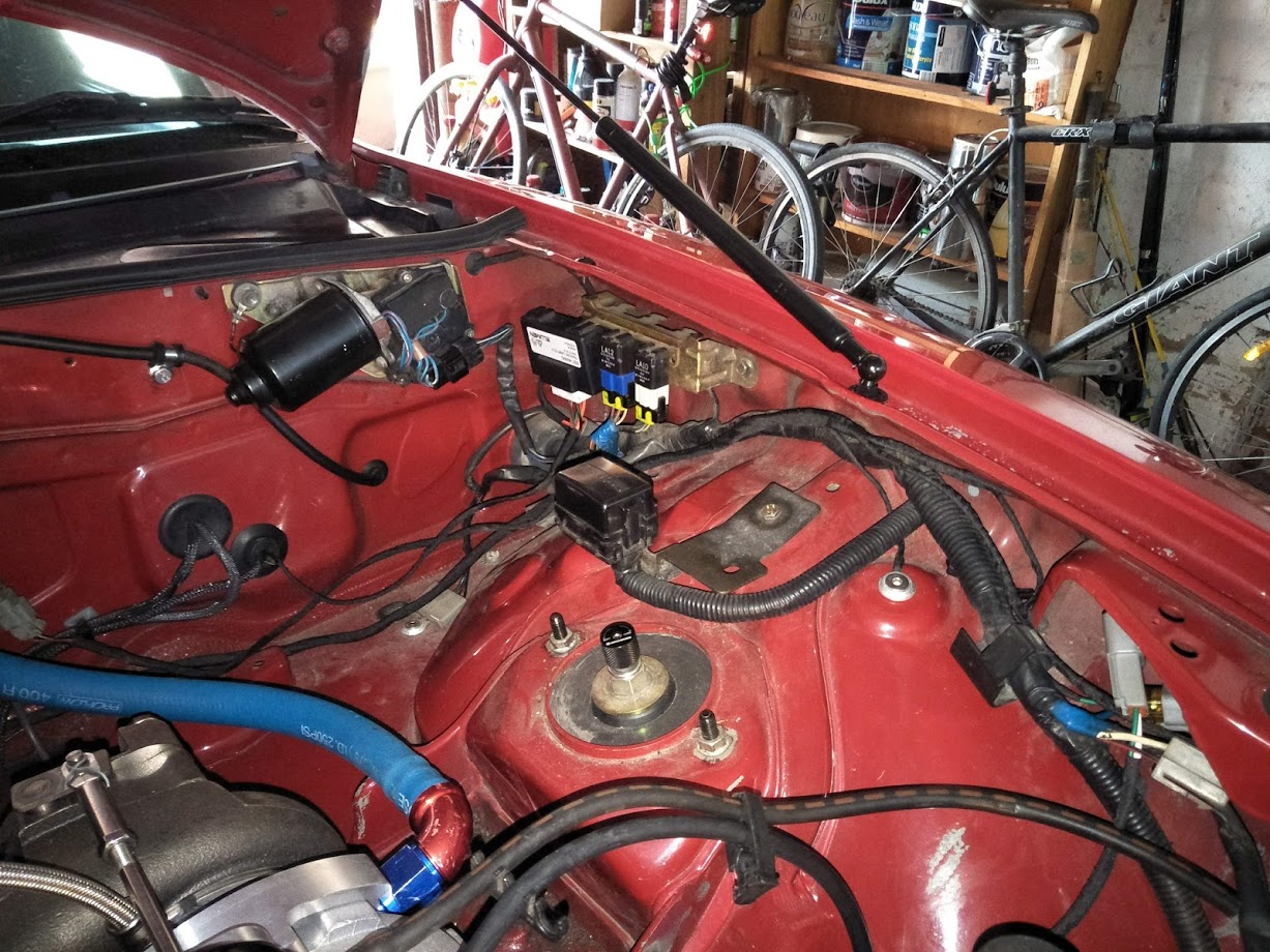
Wiring for the engines water pump. Solid state PWM driver mounted next to the OEM relays in the corner. I re-purposed a trailer lighting module from my old job since it uses solid state relays.
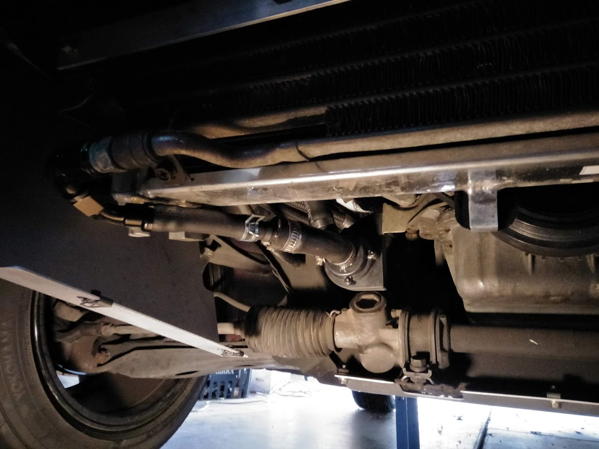
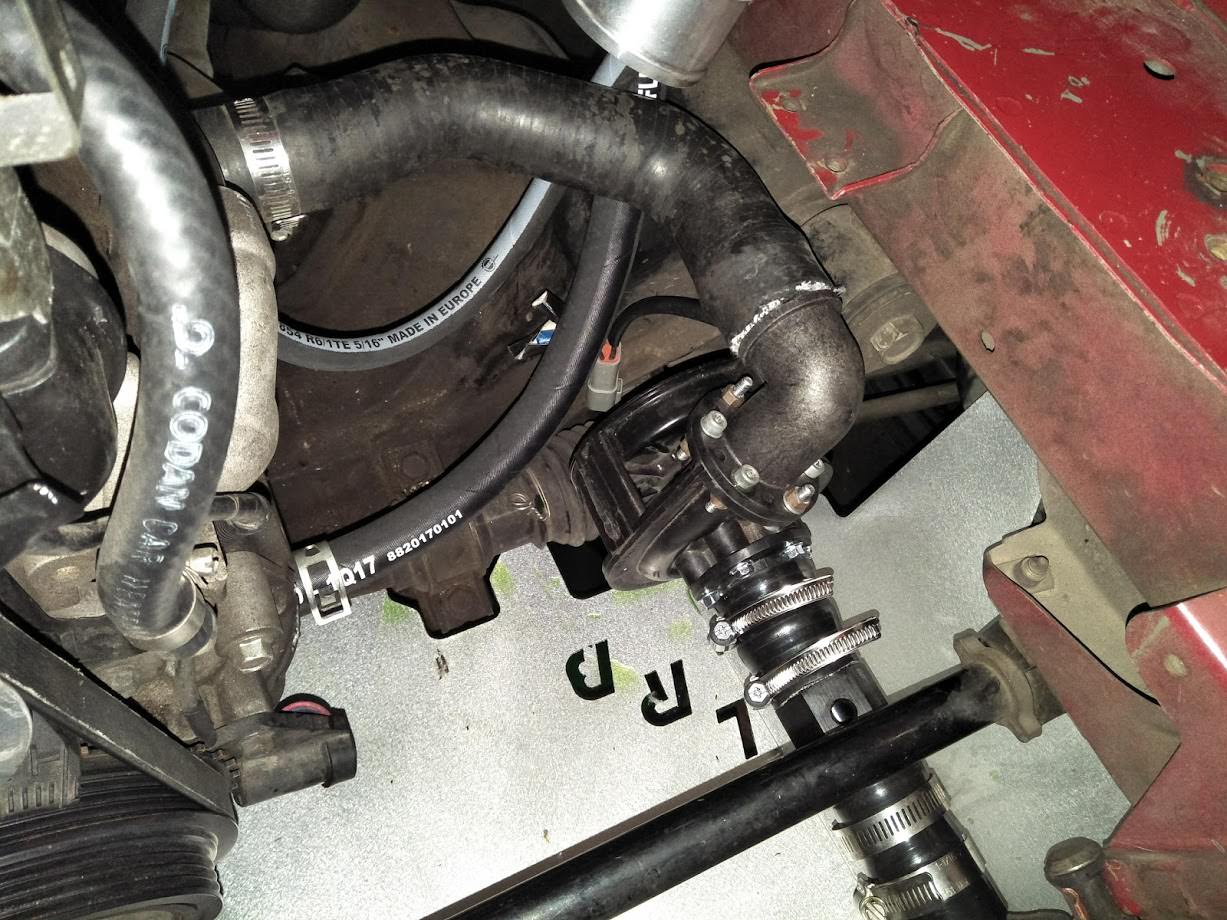
Heater return had to be moved before the water pump so that the water would flow correctly through the heater core. OEM hardline has been deleted.
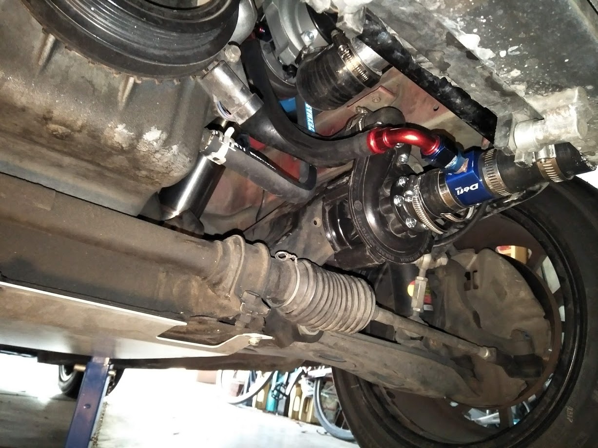
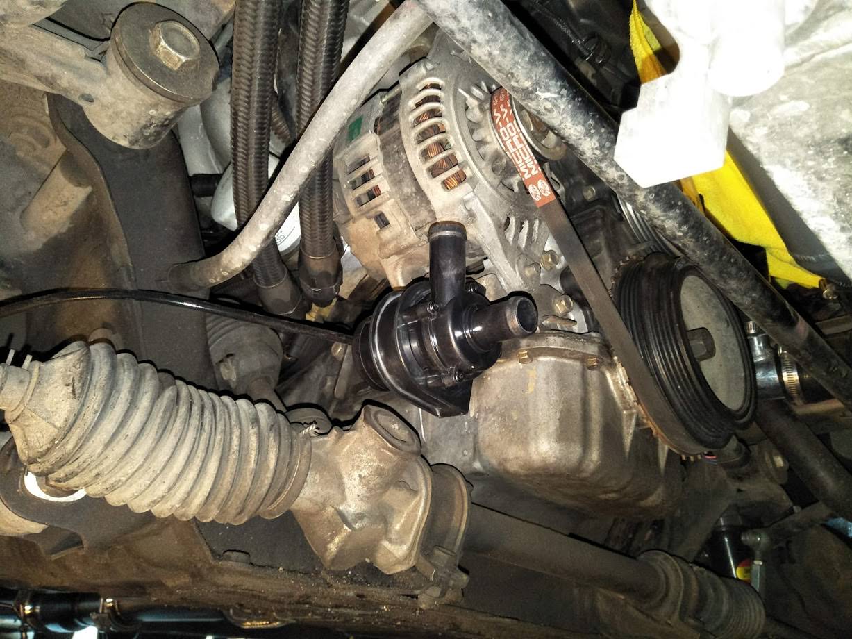
Intercooler EWP mounted just below the alternator.
Kraken turbo kit is bolted on with a Garrett GTX2860R turbo.
Dump pipe clearance is pretty tight with the brake line. Brake line will definitely need to be bend out of the way or re-routed some other way
Electric water pump for the intercooler. It's a small Davies Craig EBP23.
Also installed another electric water pump for the engine coolant. Davies Craig EWP80 pump. Fit nicely inbetween the OEM lower radiator hose. Will be dr�ven indirectly by the ECU through a high current relay module so that the pump speed can be controlled.
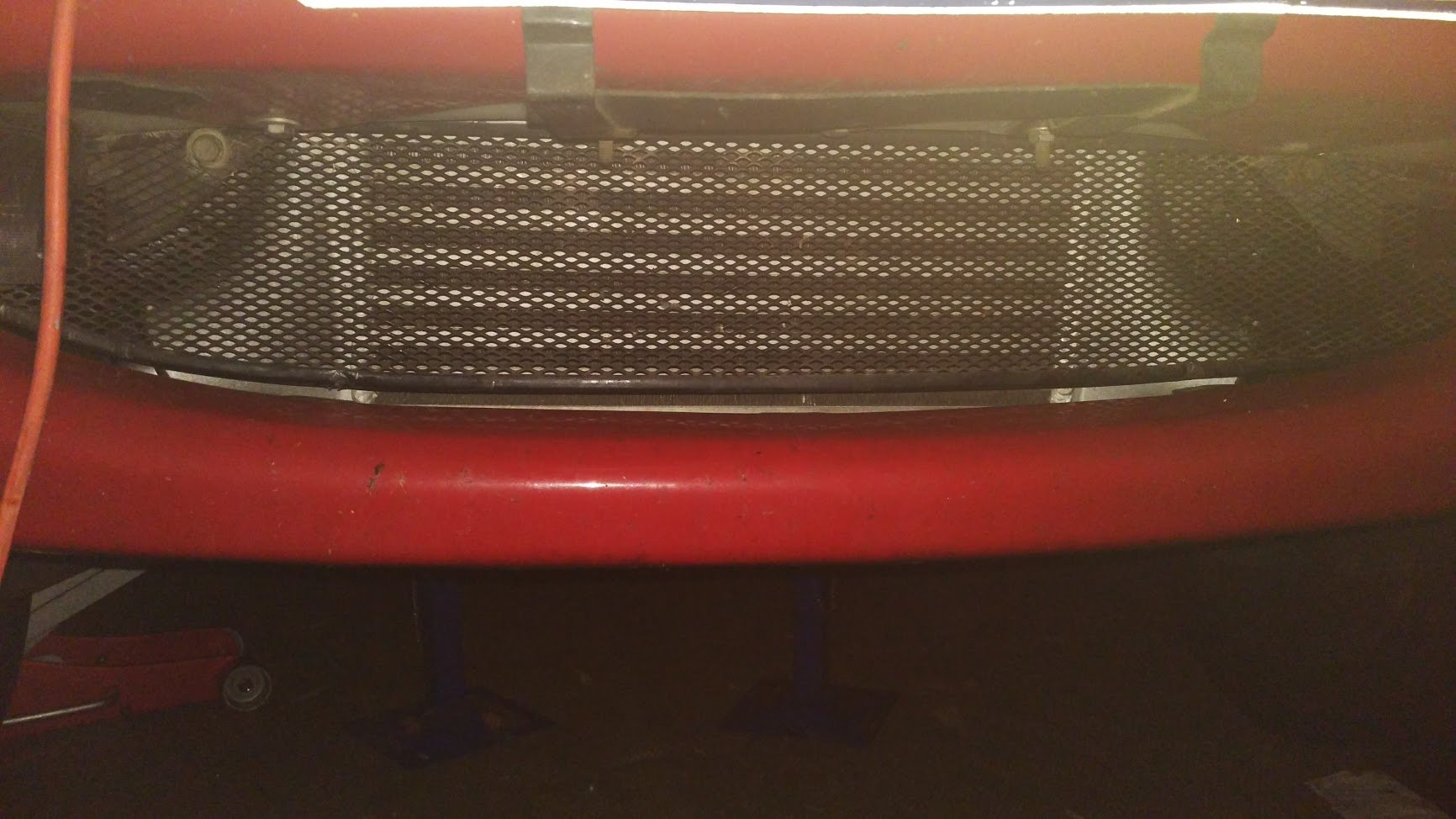
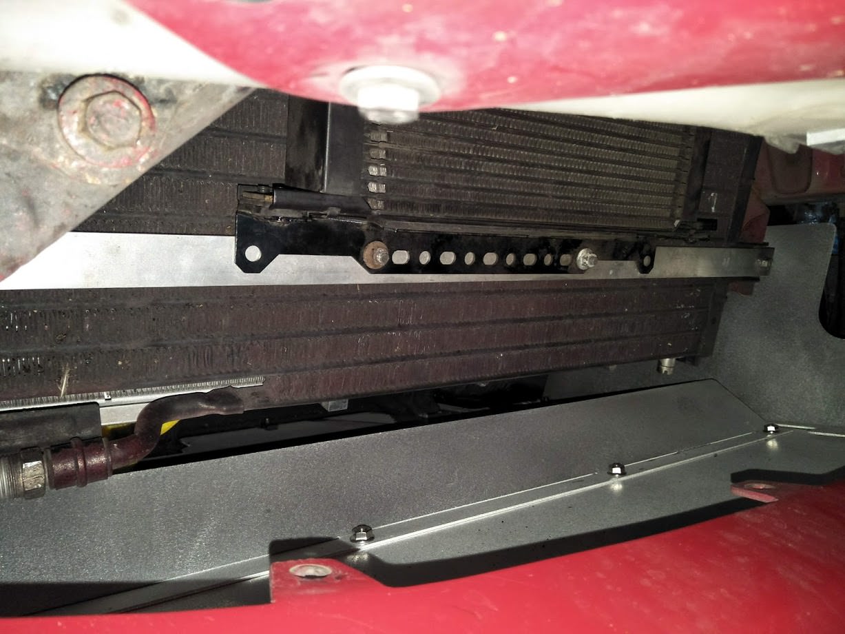
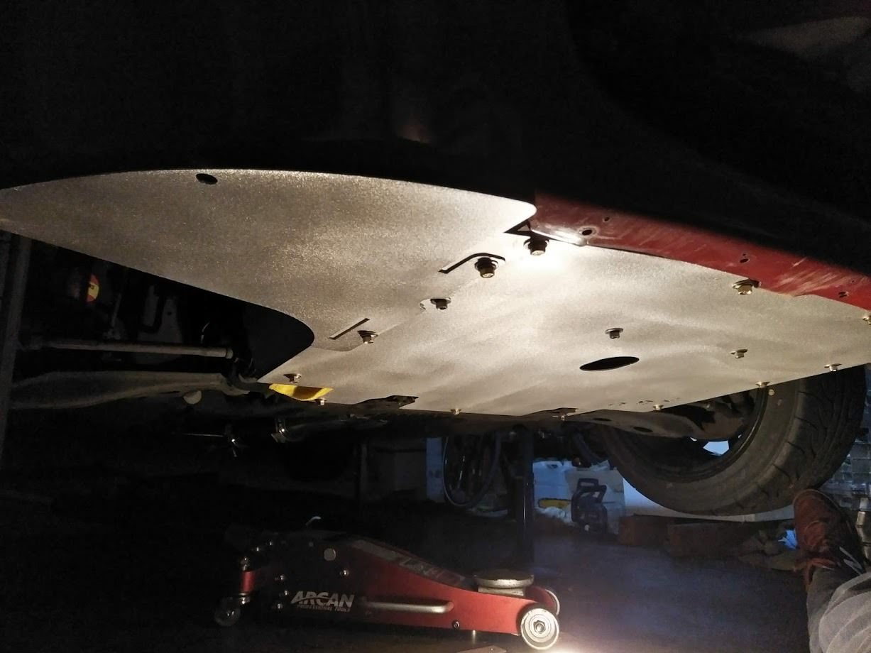
Last thing added on for the moment is a LRB undertray. Covers quite a large area under the front of the car and also does a nice job of blocking off the sides of the radiator to prevent air from bypassing the radiator through the wheel well.
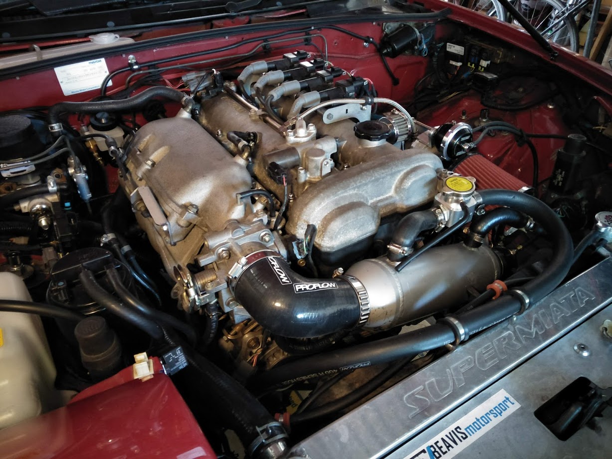
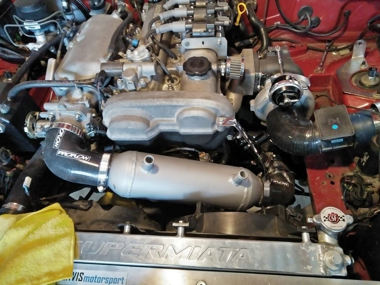
Intake fitted but not finished. Need to weld on some hose barbs for bov return and crank case ventilation as well as change the last silicone joiner to a 45 degree to get the air filter away from the exhaust.
Definitely also needs a heat shield over the turbo and manifold.
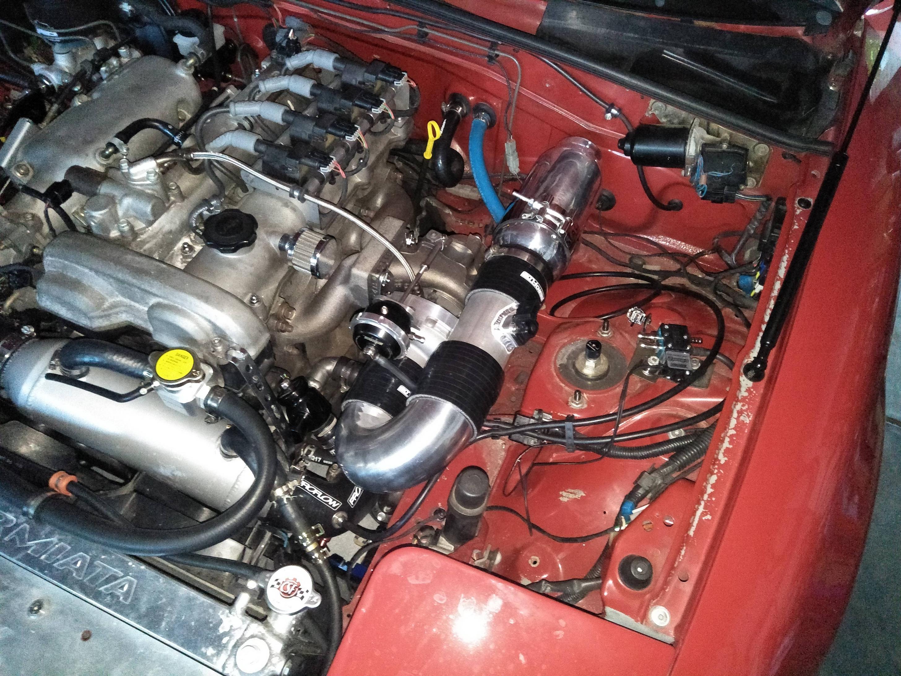
Also if you're wondering, the sensor in the intake pipe is a GM MAF.
Car is up and running now although not quite finished. Moved the intake over a bit with a 45 degree joiner however I need to figure out how to get air from outside the engine bay to improve intake temperaturs further. Obvious choice is to cut a hole in the firewall and get air from the cowl area but will refrain from cutting the body of the car just yet.
Intake temps aren't too bad anyway but could possibly be improved with a cold air intake.
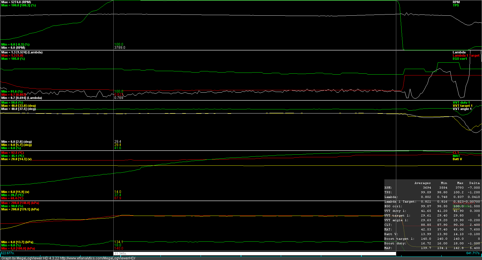
Did a test on the freeway at 100km/h when ambient temp was ~28degC. Held WOT while holding the handbrake to prevent vehicle speed from increasing for about 11 seconds. Intake temps increased ~10 degrees over that time from 33 to 44. Boost pressure was 140kPa so going higher should make the temp increase worse.
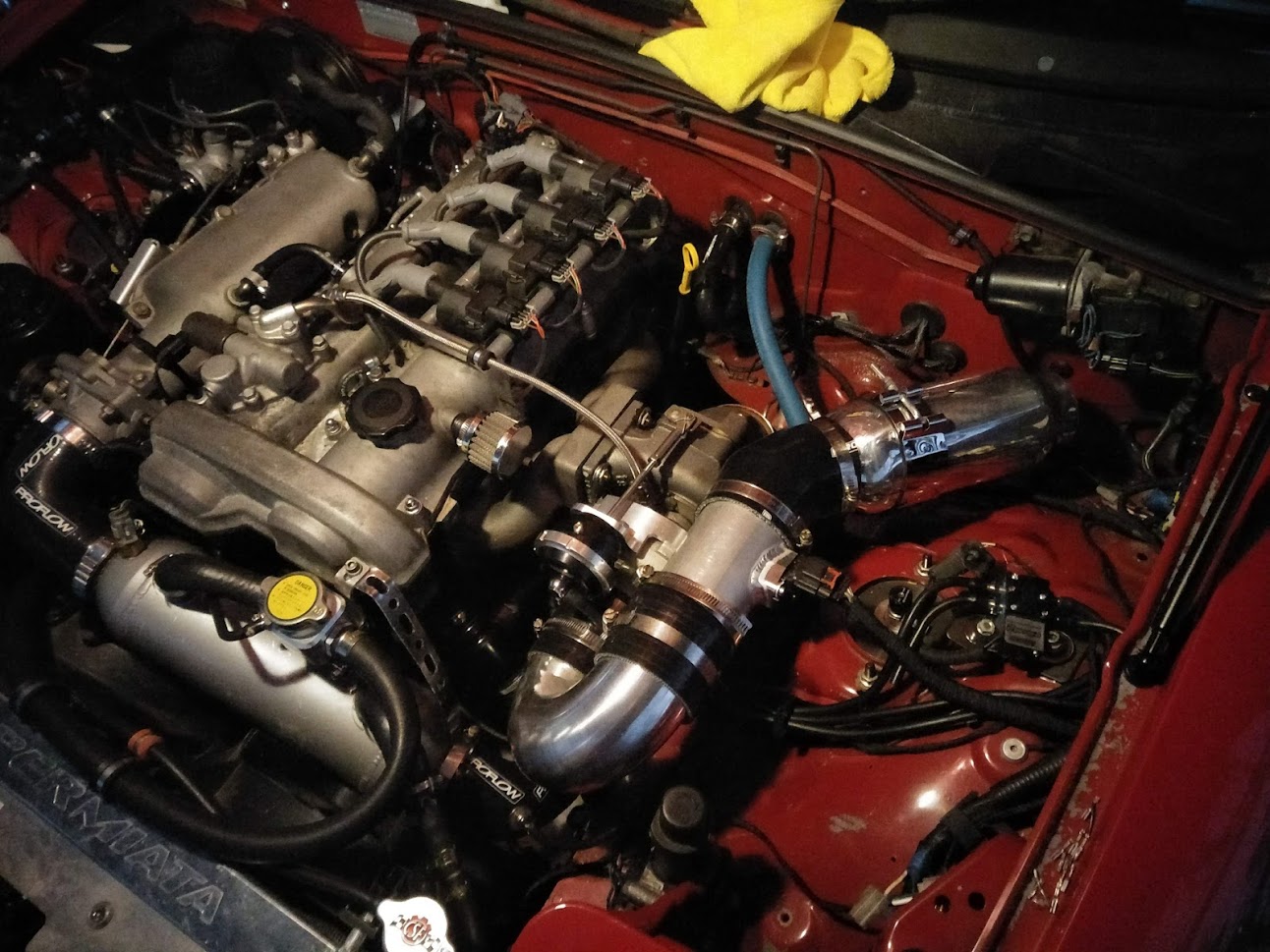
Swapped my OEM hardtop out for a Lightyear carbon fibre one.
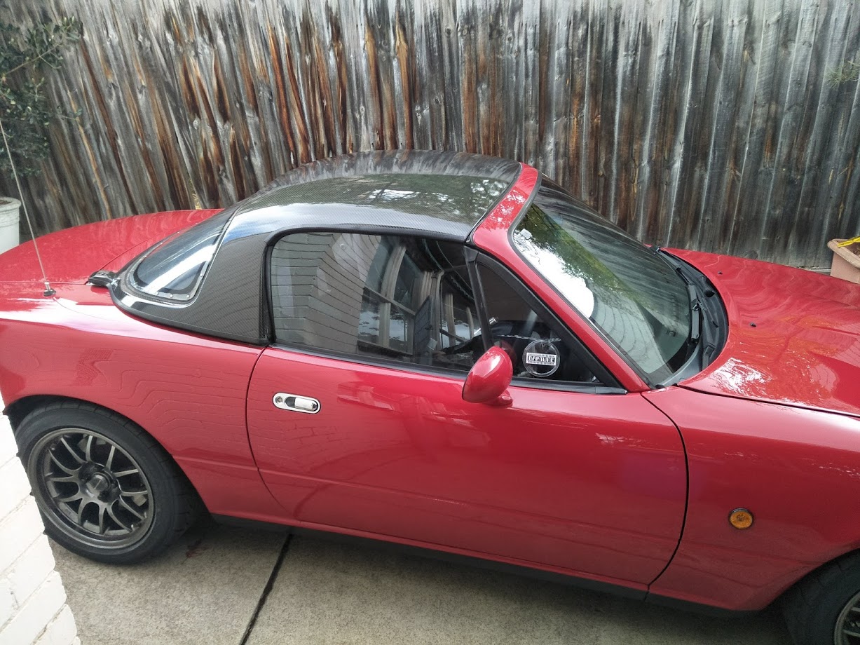
Nice weight saving but did require a bit of work adding seals to the side windows and I might need to re-seal the rear window since it can leak slightly in heavy rain. Not a huge deal though..
Also had some some help making a heat shield for the turbo and manifold. Very happy with the end result. Definitely helps keep the components over on that side of the engine bay a bit cooler which is good since my relay controller for the water pump is located there. I had some concern with how well it would continue to work when getting very hot.
I have also added a radium fuel pressure regulator housing with a Bosch 60psi regulator and a NB8B fuel rail to create a returnless system. Well its sort of returnless since the fuel still comes up to the regulator and then back to the tank however it no longer passes through the fuel rail. Made for simpler hose routing and possibly will reduce fuel temps. The regulator is still manifold vacuum referenced as well. Can see it located just behind the intake manifold. Now I have to go back and re-calibrate my fuel tables...not a huge deal since the plan is to get the GM MAF working and use that for steady state fuel calculations anyway.
Relays added for the secondary radiator fan and intercooler pump patched into the original AC connector which provides 12V and a circuit that goes back to the ECU for control.
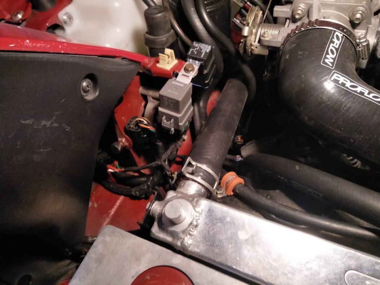
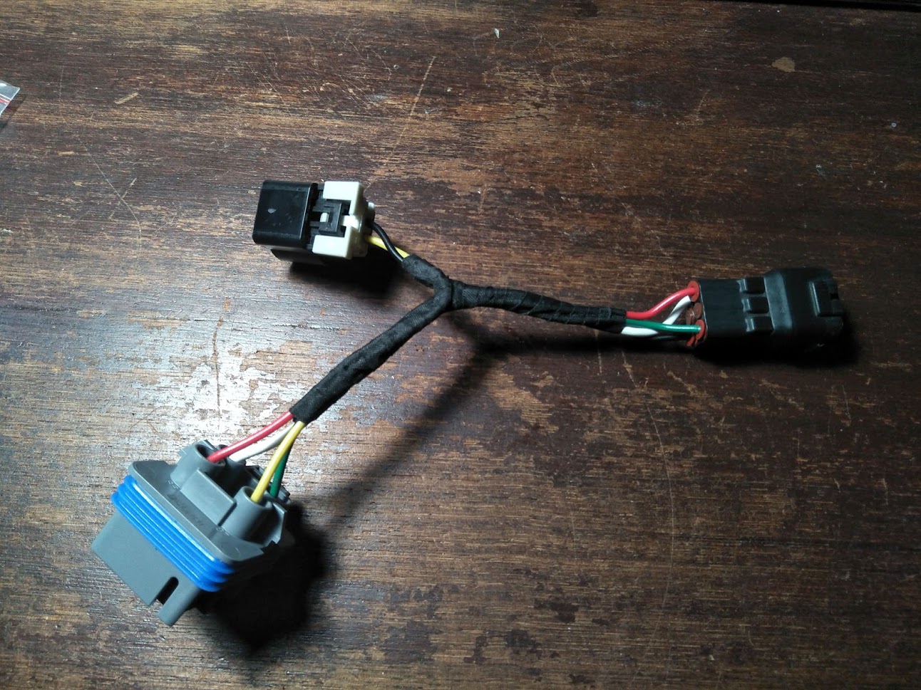
Harness plugs into the original blanked AC relay connector under the drivers headlight.
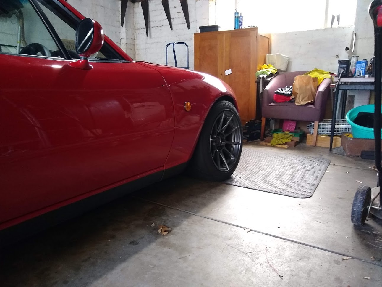
Swapped my 6ULs for some Advanti Storms 15x9.
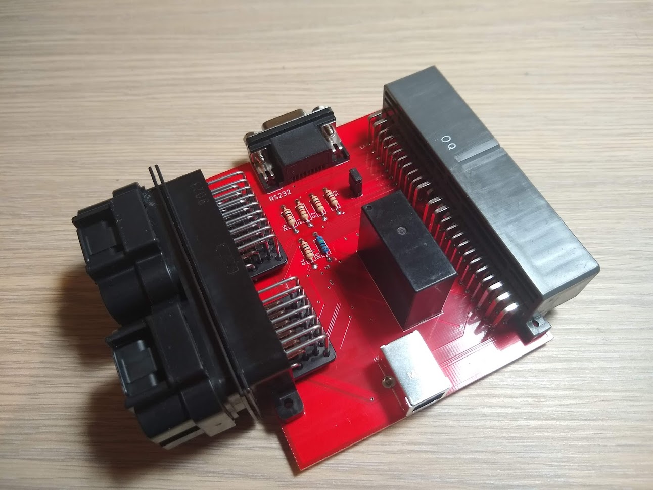
I also recently took out the MS3x ECU to add a MAF frequency input but I can't stand how messy it all is after all the changes I've made over the years so I've decided to design an adapter board to use a MS3pro gen1 ECU I have been holding onto.
I've made something similar for a mates RX7 FD.
MS3pro PCB adapter board is assembled! Now just need to make the patch harness to go between this board and the ms3pro. Just waiting on some new wire to do that. The board has a USB and serial connector for communication to the ECU, two superseal connectors (commonly used on aftermarket ECUs like Motec and Haltechs), the MX-5 ECU connector to match the OEM harness, some pull-up resistors for things like temperature sensors etc, and a relay to control power to the wideband controller.
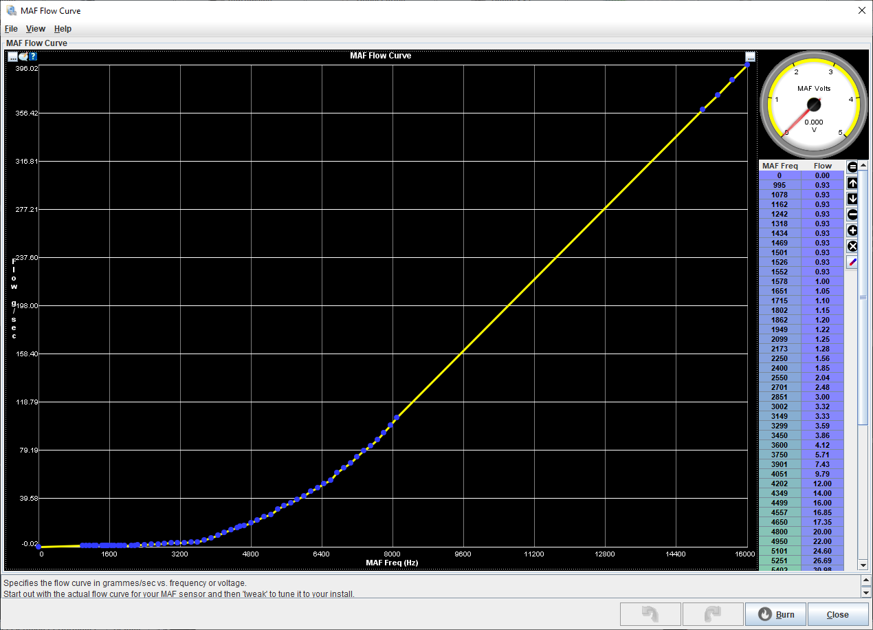
I've also got my MAF working and roughed in a airflow curve for it. Very easy to calibrate however it doesn't appear to be accurately measuring low airflow around idle, probably since it's in a 3" pipe and there's a bend right before the MAF. In the future I will replace the pipe with one that has airflow straighteners which should fix it but for now I can canfigure the ECU to blend the old speed-density tune at low airflow.
I also installed a set of superpro poly bushes in the a-arms so needed to get a wheel alignment.
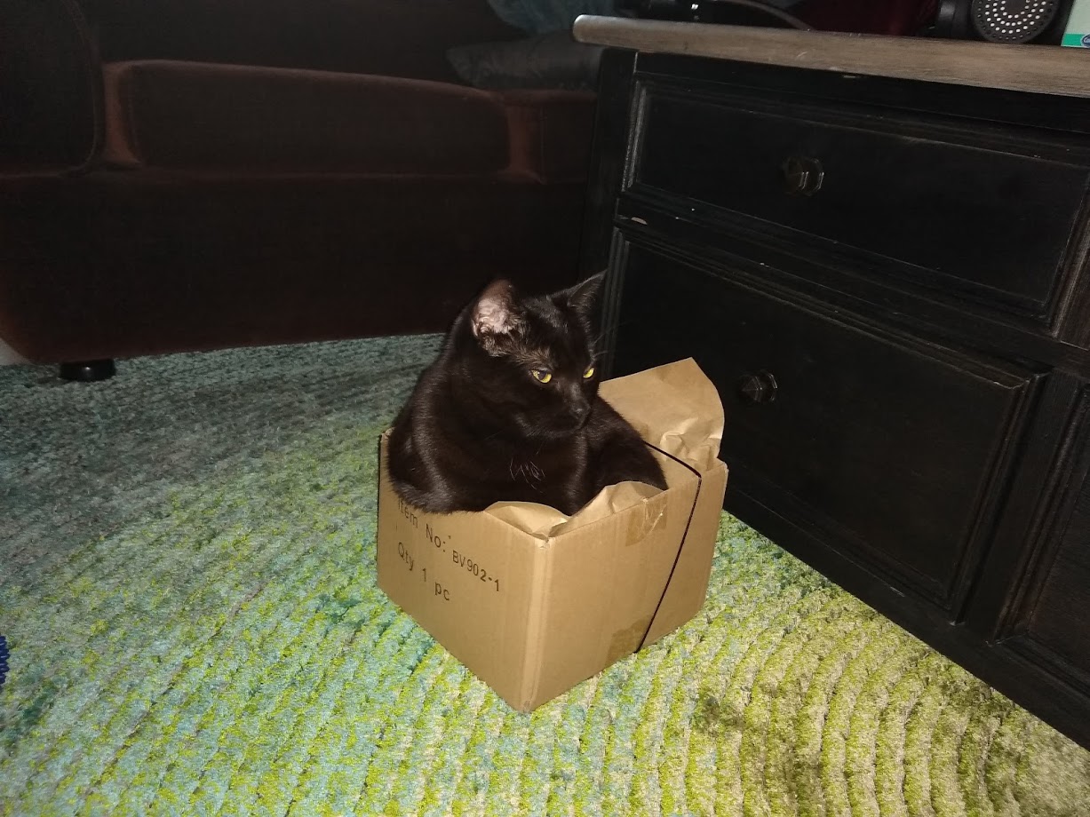
Bonus picture of my cat in a box.
I haven't really had much time for this car over the last year due to work but a few things have happened.
It's turbo again thanks to Kraken!
As you can probably work out I've decided to use a water to air intercooler setup this time. Aim is to get the best response possible and keep intake temperatures very consistent. Biggest bonus for me is that I don't have an obvious intercooler visible at the front of the car. A/C condensor is being used as the heat exchanger for the intercooler since it as free and bolts straight up. Possibly not the best choice but so far it seems to be holding up well enough. Worst case I can swap back to using an air to air setup with the xr6 intercooler I used previously.
Wiring for the engines water pump. Solid state PWM driver mounted next to the OEM relays in the corner. I re-purposed a trailer lighting module from my old job since it uses solid state relays.
Heater return had to be moved before the water pump so that the water would flow correctly through the heater core. OEM hardline has been deleted.
Intercooler EWP mounted just below the alternator.
Kraken turbo kit is bolted on with a Garrett GTX2860R turbo.
Dump pipe clearance is pretty tight with the brake line. Brake line will definitely need to be bend out of the way or re-routed some other way
Electric water pump for the intercooler. It's a small Davies Craig EBP23.
Also installed another electric water pump for the engine coolant. Davies Craig EWP80 pump. Fit nicely inbetween the OEM lower radiator hose. Will be dr�ven indirectly by the ECU through a high current relay module so that the pump speed can be controlled.
Last thing added on for the moment is a LRB undertray. Covers quite a large area under the front of the car and also does a nice job of blocking off the sides of the radiator to prevent air from bypassing the radiator through the wheel well.
Intake fitted but not finished. Need to weld on some hose barbs for bov return and crank case ventilation as well as change the last silicone joiner to a 45 degree to get the air filter away from the exhaust.
Definitely also needs a heat shield over the turbo and manifold.
Also if you're wondering, the sensor in the intake pipe is a GM MAF.
Car is up and running now although not quite finished. Moved the intake over a bit with a 45 degree joiner however I need to figure out how to get air from outside the engine bay to improve intake temperaturs further. Obvious choice is to cut a hole in the firewall and get air from the cowl area but will refrain from cutting the body of the car just yet.
Intake temps aren't too bad anyway but could possibly be improved with a cold air intake.
Did a test on the freeway at 100km/h when ambient temp was ~28degC. Held WOT while holding the handbrake to prevent vehicle speed from increasing for about 11 seconds. Intake temps increased ~10 degrees over that time from 33 to 44. Boost pressure was 140kPa so going higher should make the temp increase worse.
Swapped my OEM hardtop out for a Lightyear carbon fibre one.
Nice weight saving but did require a bit of work adding seals to the side windows and I might need to re-seal the rear window since it can leak slightly in heavy rain. Not a huge deal though..
Also had some some help making a heat shield for the turbo and manifold. Very happy with the end result. Definitely helps keep the components over on that side of the engine bay a bit cooler which is good since my relay controller for the water pump is located there. I had some concern with how well it would continue to work when getting very hot.
I have also added a radium fuel pressure regulator housing with a Bosch 60psi regulator and a NB8B fuel rail to create a returnless system. Well its sort of returnless since the fuel still comes up to the regulator and then back to the tank however it no longer passes through the fuel rail. Made for simpler hose routing and possibly will reduce fuel temps. The regulator is still manifold vacuum referenced as well. Can see it located just behind the intake manifold. Now I have to go back and re-calibrate my fuel tables...not a huge deal since the plan is to get the GM MAF working and use that for steady state fuel calculations anyway.
Relays added for the secondary radiator fan and intercooler pump patched into the original AC connector which provides 12V and a circuit that goes back to the ECU for control.
Harness plugs into the original blanked AC relay connector under the drivers headlight.
Swapped my 6ULs for some Advanti Storms 15x9.
I also recently took out the MS3x ECU to add a MAF frequency input but I can't stand how messy it all is after all the changes I've made over the years so I've decided to design an adapter board to use a MS3pro gen1 ECU I have been holding onto.
I've made something similar for a mates RX7 FD.
MS3pro PCB adapter board is assembled! Now just need to make the patch harness to go between this board and the ms3pro. Just waiting on some new wire to do that. The board has a USB and serial connector for communication to the ECU, two superseal connectors (commonly used on aftermarket ECUs like Motec and Haltechs), the MX-5 ECU connector to match the OEM harness, some pull-up resistors for things like temperature sensors etc, and a relay to control power to the wideband controller.
I've also got my MAF working and roughed in a airflow curve for it. Very easy to calibrate however it doesn't appear to be accurately measuring low airflow around idle, probably since it's in a 3" pipe and there's a bend right before the MAF. In the future I will replace the pipe with one that has airflow straighteners which should fix it but for now I can canfigure the ECU to blend the old speed-density tune at low airflow.
I also installed a set of superpro poly bushes in the a-arms so needed to get a wheel alignment.
Bonus picture of my cat in a box.
Reply
0
0

Thread Starter
Junior Member
Joined: Jun 2015
Posts: 182
Total Cats: 58
From: VIC, Australia
I didn't take any pictures but I did bend the brake line further away from the dump pipe and the heatshield also extends down there between the dump pipe and brake lines. Still wouldn't hurt to add an extra layer of insulation over the top. It's on my list of things to do.
Reply
0
0
Thread Starter
Junior Member
Joined: Jun 2015
Posts: 182
Total Cats: 58
From: VIC, Australia
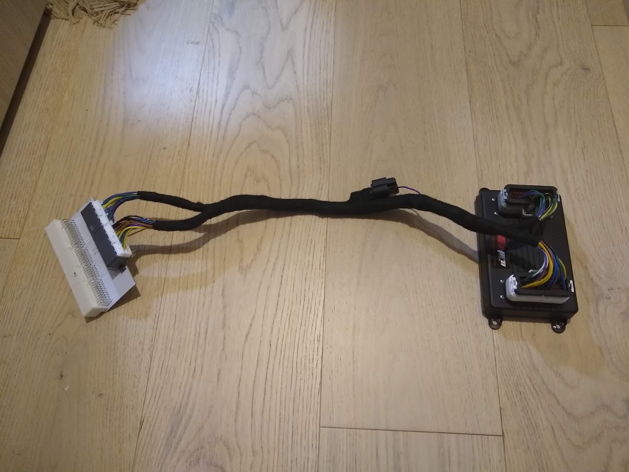
Finally had a bit of free time so finished off my ms3pro adapter...well amost. It still needs a case for the adapter board.
I bought various wire colours in the sizes I needed to make it easier to identify circuits. There's still duplicates however it's still better than having them all the same colour.
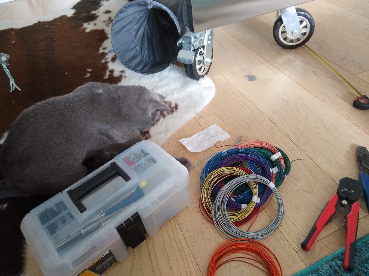
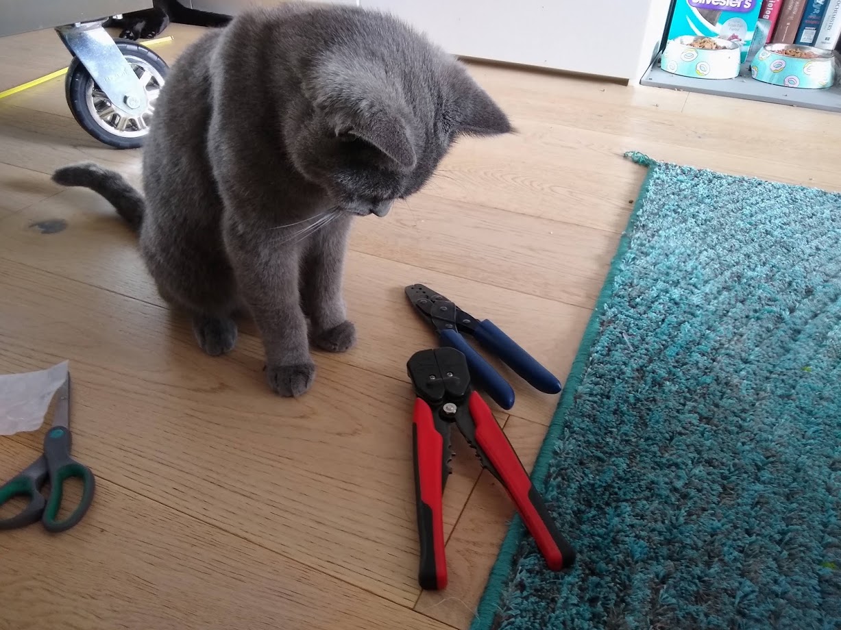
I had a bit of 'help' cutting and crimping.
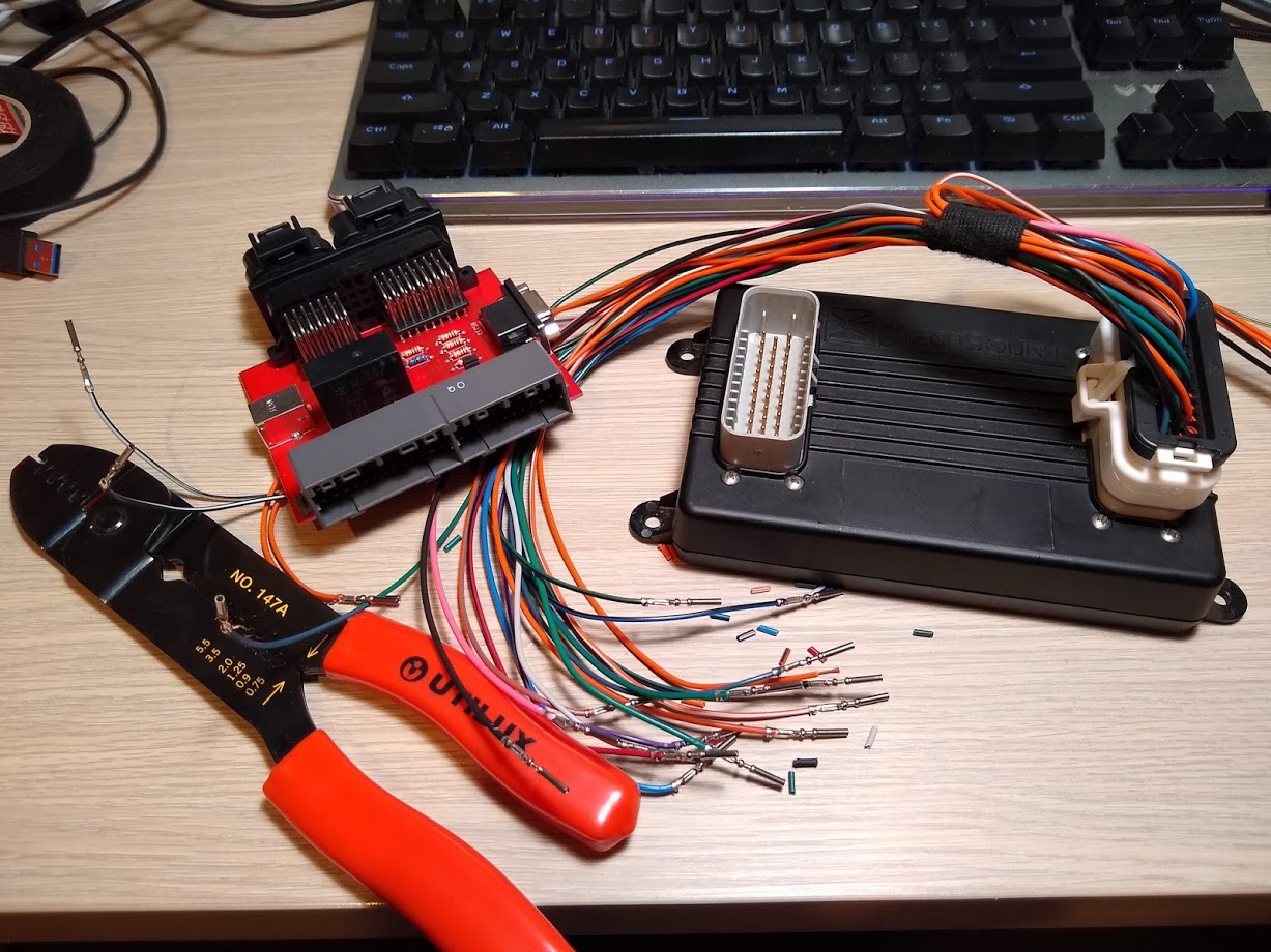
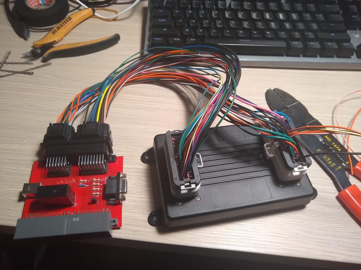
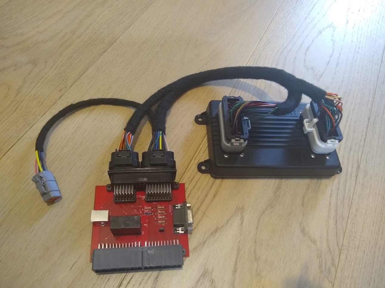
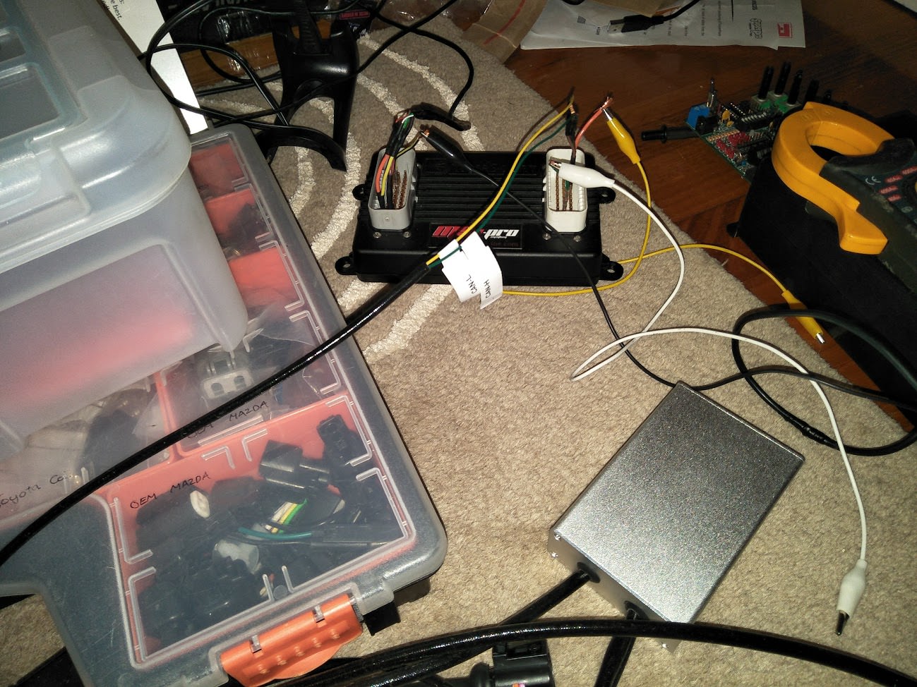
Hopefully will fit neatly under the passenger kick panel. The extra connector is to supply power to the wideband as well as CAN communication.
I bought various wire colours in the sizes I needed to make it easier to identify circuits. There's still duplicates however it's still better than having them all the same colour.
I had a bit of 'help' cutting and crimping.
Hopefully will fit neatly under the passenger kick panel. The extra connector is to supply power to the wideband as well as CAN communication.
Reply
1
1


