build thread (TII drivetrain swap, built motor, cage, widebody, blah blah)
 08-12-2008, 10:51 AM
#101
Senior Member
Thread Starter
iTrader: (9)

Join Date: Jun 2007
Location: NH
Posts: 1,013
Total Cats: 21
your turbo diff solid mount is very clean. I did a RX7 turbo II diff approx 2 yrs ago used a plate and welded to subframe then placed a rubber mount in between the solid plate and diff. Here is a link to my install.
http://www.cardomain.com/ride/613741
Please let me know if anything cracks in your mount due to fact may revamp my mount. Good luck on your build looks very nice.
http://www.cardomain.com/ride/613741
Please let me know if anything cracks in your mount due to fact may revamp my mount. Good luck on your build looks very nice.

Reply
 0
0

0
08-12-2008, 12:04 PM
#102
Junior Member
iTrader: (1)

Join Date: Jul 2007
Location: Johannesburg, South Africa
Posts: 109
Total Cats: 0
absolutely awesome congrats and well done !
my only question is about the rust, surely with a build like this it would be easier to send those parts away for sandblasting / proper painting or buy less rusted ones from ebay or similiar - some of the pics of the painted parts dont look so kosher to me or is it just the camera ?
my only question is about the rust, surely with a build like this it would be easier to send those parts away for sandblasting / proper painting or buy less rusted ones from ebay or similiar - some of the pics of the painted parts dont look so kosher to me or is it just the camera ?
Reply
0
0
08-12-2008, 02:41 PM
#103
Senior Member
Thread Starter
iTrader: (9)
Join Date: Jun 2007
Location: NH
Posts: 1,013
Total Cats: 21
absolutely awesome congrats and well done !
my only question is about the rust, surely with a build like this it would be easier to send those parts away for sandblasting / proper painting or buy less rusted ones from ebay or similiar - some of the pics of the painted parts dont look so kosher to me or is it just the camera ?
my only question is about the rust, surely with a build like this it would be easier to send those parts away for sandblasting / proper painting or buy less rusted ones from ebay or similiar - some of the pics of the painted parts dont look so kosher to me or is it just the camera ?
Reply
0
0

 08-23-2008, 10:13 PM
#106
Senior Member
Thread Starter
iTrader: (9)
Join Date: Jun 2007
Location: NH
Posts: 1,013
Total Cats: 21
Yeah I think they all would due to the size of the boot. Maybe over the winter I'll look around and see if I can get a smaller boot if that's possible?
updates!
More progress...Took Thur and Fri off from work and worked on the car.
I notched out the section between the shock tower braces 2 1/8" in by 1 1/8" tall.
Now the wastegate fits :roll: .
closeup of the cut. There is a little bit more bracing in there, I'm going to have to brace it back up with some gussets as this is a pretty high stress area.
side view
Next, I clocked the turbo so that it was positioned correctly for the manifold. Here it is positioned with the water lines more or less where they will be run. The oil feed is just laying loose, I still need a 10x1.5mm to -4an fitting for the block.
side view
Since I had to cut the frame, I'm going to have to paint the cut section so the new bracket doesn't rust, so I decided to just go ahead and spray the whole bay, something I should have done a long time ago. What a world of a difference.
I started to remove the wiring harness and the headlight bracketry/controls.
I sanded, primed and painted everything.
Priming....
Painted
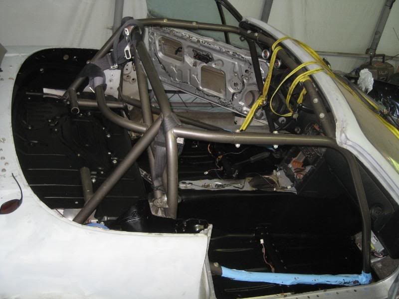
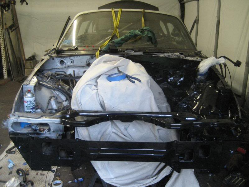
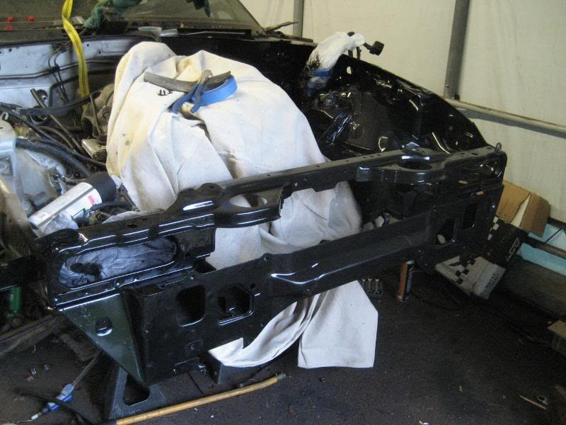
I also prepped/primed/painted the interior access panels and the entire interior. Everything is getting painted satin black.
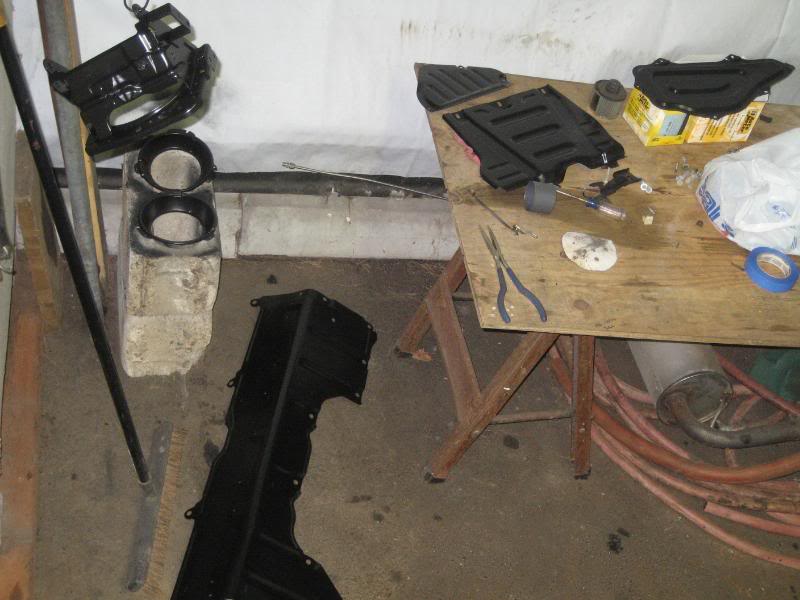
interior shot
updates!
More progress...Took Thur and Fri off from work and worked on the car.
I notched out the section between the shock tower braces 2 1/8" in by 1 1/8" tall.
Now the wastegate fits :roll: .
closeup of the cut. There is a little bit more bracing in there, I'm going to have to brace it back up with some gussets as this is a pretty high stress area.
side view
Next, I clocked the turbo so that it was positioned correctly for the manifold. Here it is positioned with the water lines more or less where they will be run. The oil feed is just laying loose, I still need a 10x1.5mm to -4an fitting for the block.
side view
Since I had to cut the frame, I'm going to have to paint the cut section so the new bracket doesn't rust, so I decided to just go ahead and spray the whole bay, something I should have done a long time ago. What a world of a difference.
I started to remove the wiring harness and the headlight bracketry/controls.
I sanded, primed and painted everything.
Priming....
Painted
I also prepped/primed/painted the interior access panels and the entire interior. Everything is getting painted satin black.
interior shot
Reply
0
0
08-23-2008, 10:15 PM
#107
Senior Member
Thread Starter
iTrader: (9)
Join Date: Jun 2007
Location: NH
Posts: 1,013
Total Cats: 21
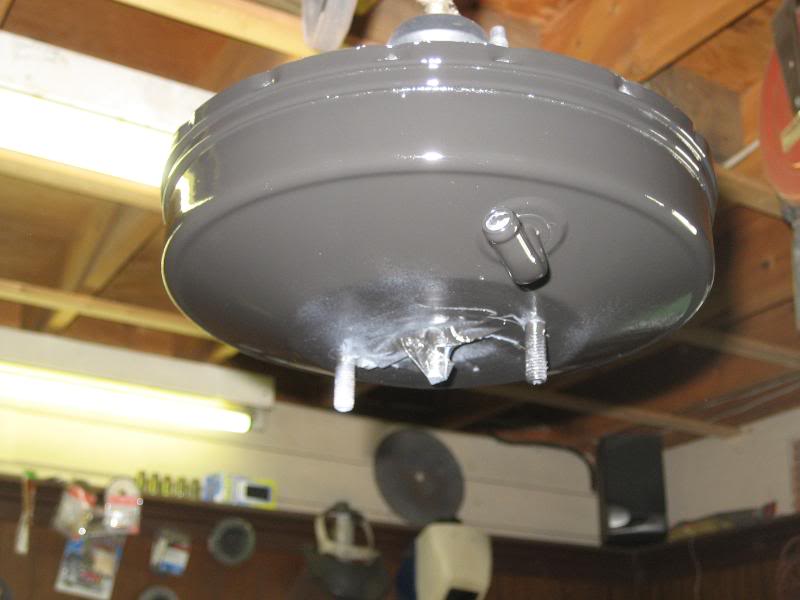
prepped/primed/painted the brake booster.
Took apart the starter, cleaned it up some and painted it as well.
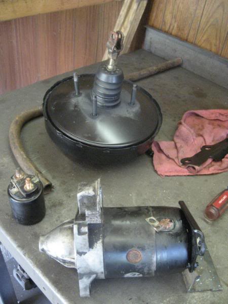
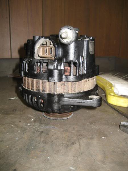
Painted the alternator....For the starter and alternator I used the brake caliper paint again as I figured it would hold up to the heat a bit better
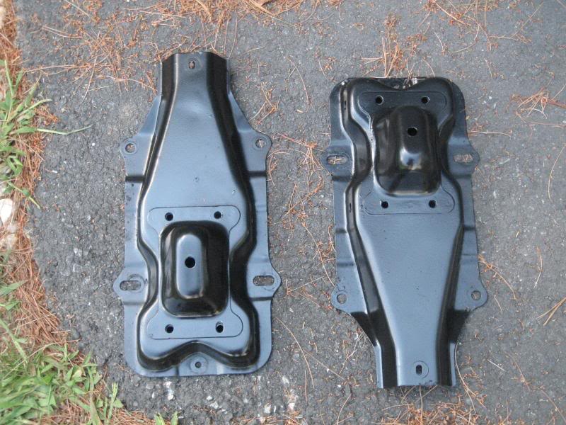
painted the front bumper supports
and installed the access panels back in the car because I kept tripping over them
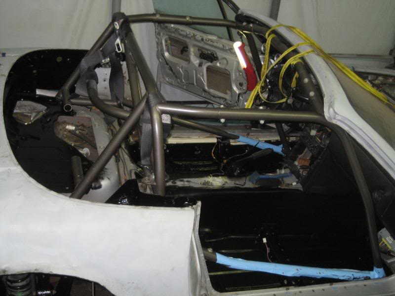
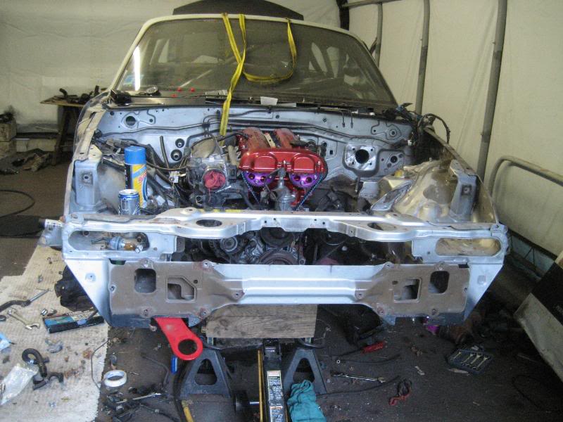
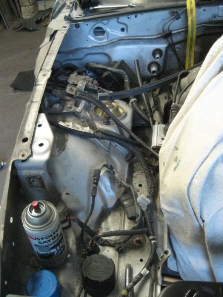
Here's another shot of the engine bay before tear down
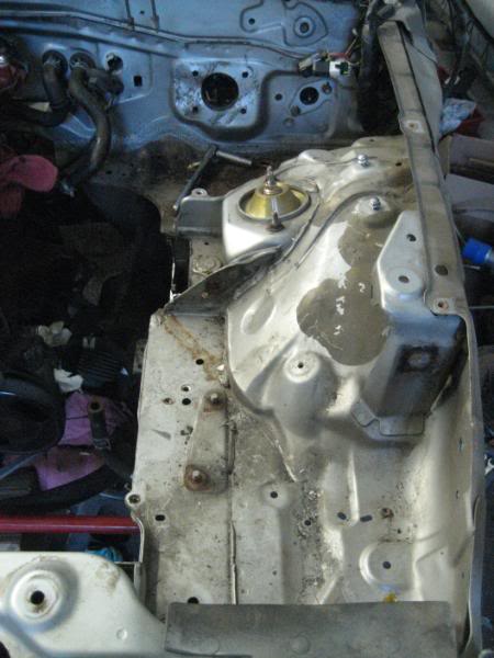
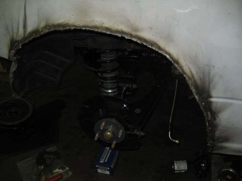
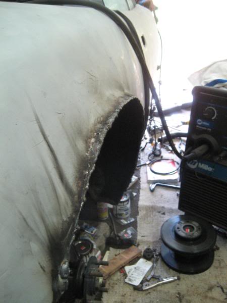
I removed both fenders as well. Took the intercooler and radiator back out and anything else that would interfere with the painting off the engine bay. I started with the driver's side as it's much easier.
it's filthy
during the process of painting
driver's side done
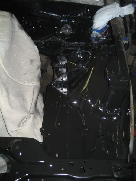
again, the engine bay is being painted in satin black
Took apart the starter, cleaned it up some and painted it as well.
Painted the alternator....For the starter and alternator I used the brake caliper paint again as I figured it would hold up to the heat a bit better
painted the front bumper supports
and installed the access panels back in the car because I kept tripping over them
Here's another shot of the engine bay before tear down
I removed both fenders as well. Took the intercooler and radiator back out and anything else that would interfere with the painting off the engine bay. I started with the driver's side as it's much easier.
it's filthy
during the process of painting
driver's side done
again, the engine bay is being painted in satin black
Reply
0
0
08-23-2008, 10:17 PM
#108
Senior Member
Thread Starter
iTrader: (9)
Join Date: Jun 2007
Location: NH
Posts: 1,013
Total Cats: 21
The camera makes the paint look weird for some odd reason, but it came out perfect (just an fyi).
Now the passenger side....sigh, there's significantly more junk over here
All done
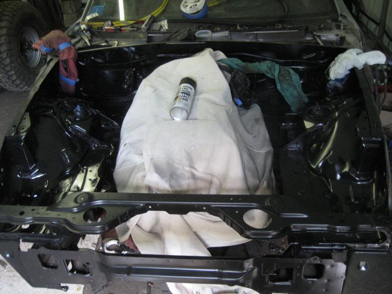
close up
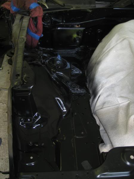
What a significant difference. I'm much happier with the engine bay now.
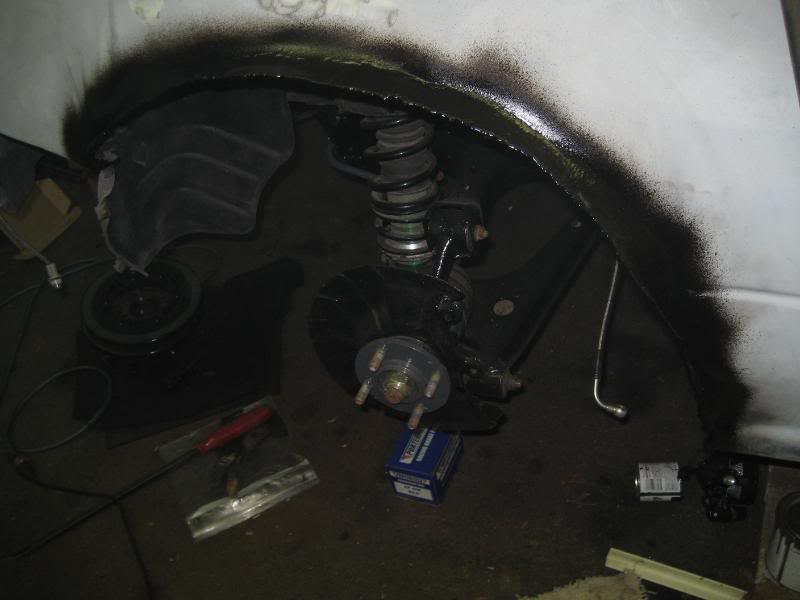
2 more of the underside
driver's side
passenger side
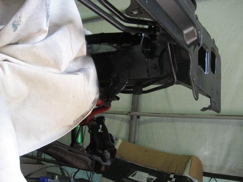
Now to make the bracket so I can box the frame back in. I got a piece of 1/8" C channel and cut it to fit. I also made 2 tabs, one to go between the existing supports, and one to be welded on the forward edge of the bracket. Here they are cut out and cleaned up with the grinder.
Tomorrow morning we start welding, so I'll have some more exciting updates tomorrow. I found a shop to bore out the center hole in my rotors, so I'm dropping them off Monday. It's starting to come together.
Now the passenger side....sigh, there's significantly more junk over here
All done
close up
What a significant difference. I'm much happier with the engine bay now.
2 more of the underside
driver's side
passenger side
Now to make the bracket so I can box the frame back in. I got a piece of 1/8" C channel and cut it to fit. I also made 2 tabs, one to go between the existing supports, and one to be welded on the forward edge of the bracket. Here they are cut out and cleaned up with the grinder.
Tomorrow morning we start welding, so I'll have some more exciting updates tomorrow. I found a shop to bore out the center hole in my rotors, so I'm dropping them off Monday. It's starting to come together.
Reply
0
0
08-23-2008, 10:26 PM
#109
Why didn't you just buy a FM II or Begi Stage 5 kit? Why do all this work for nothing? I mean, what's the point of wasting all this effort and money?
Just Kidding. Your build is unbelievable to me. I only dream I'll be able to do things like this one day to my car. You're doing a mighty fine job. Attention to detail makes all the difference. So any guess as to how many cans of paint have went into this build?
Just Kidding. Your build is unbelievable to me. I only dream I'll be able to do things like this one day to my car. You're doing a mighty fine job. Attention to detail makes all the difference. So any guess as to how many cans of paint have went into this build?
Reply
0
0
08-23-2008, 10:51 PM
#110
Senior Member
Thread Starter
iTrader: (9)
Join Date: Jun 2007
Location: NH
Posts: 1,013
Total Cats: 21
Why didn't you just buy a FM II or Begi Stage 5 kit? Why do all this work for nothing? I mean, what's the point of wasting all this effort and money?
Just Kidding. Your build is unbelievable to me. I only dream I'll be able to do things like this one day to my car. You're doing a mighty fine job. Attention to detail makes all the difference. So any guess as to how many cans of paint have went into this build?
Just Kidding. Your build is unbelievable to me. I only dream I'll be able to do things like this one day to my car. You're doing a mighty fine job. Attention to detail makes all the difference. So any guess as to how many cans of paint have went into this build?
haha. I haven't been keeping track of the paint, but it has been quite a bit.
Reply
0
0


 08-26-2008, 11:23 PM
#115
Senior Member
Thread Starter
iTrader: (9)
Join Date: Jun 2007
Location: NH
Posts: 1,013
Total Cats: 21
On to the updates! It's welding time.
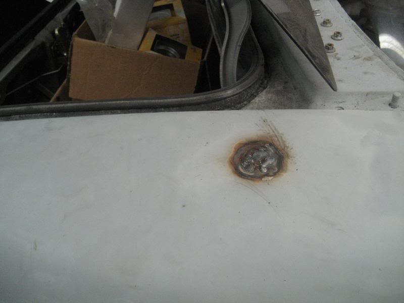
I got just about everything that needs to be welded done minus the clutch fork and exhaust, which must wait until everything is back in the car so I know how/where to route it. We started with the rear fenders. I ran a grinder over them to clean them up and clamped them together as we welded them up.
Here is a shot of both fenders all welded up before I cleaned them up a bit. I didn't go nuts smoothing the welds down as they are going to be covered anyways.
passenger rear fender
body filler burns
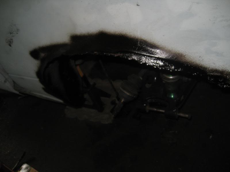
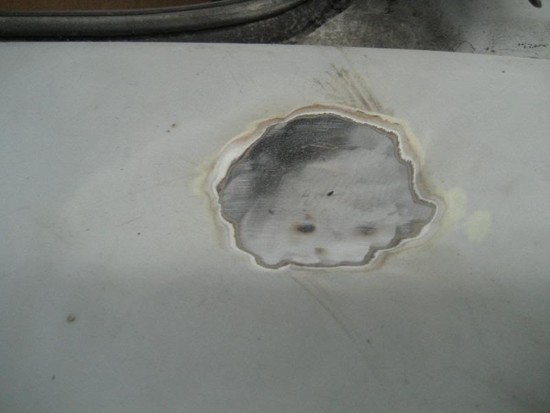
This time I ground about an inch back from the weld joint before we started
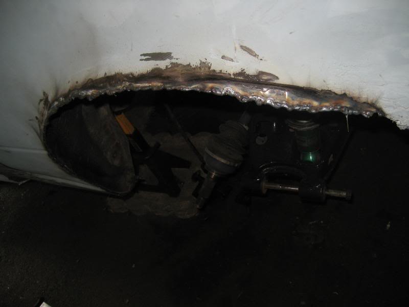
and with a coat of 3m undercoat
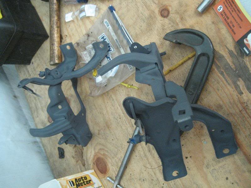
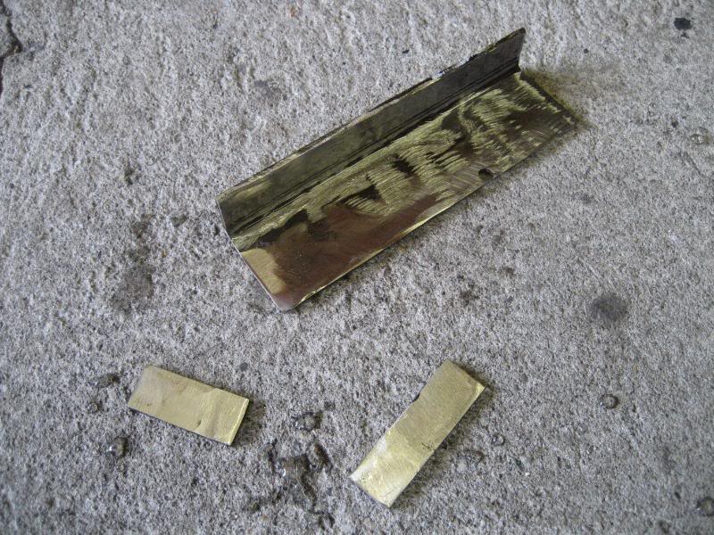
Here are some of the brackets I made for the next steps...
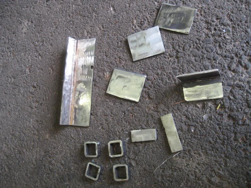
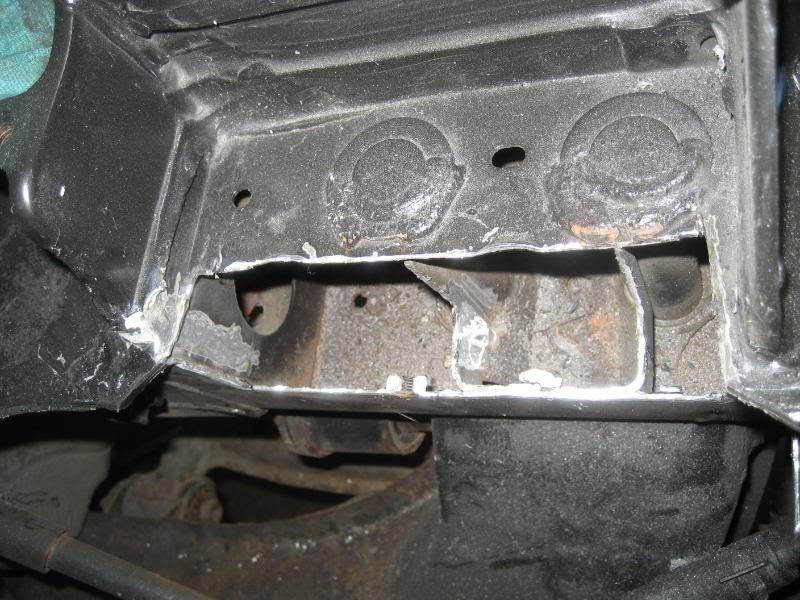
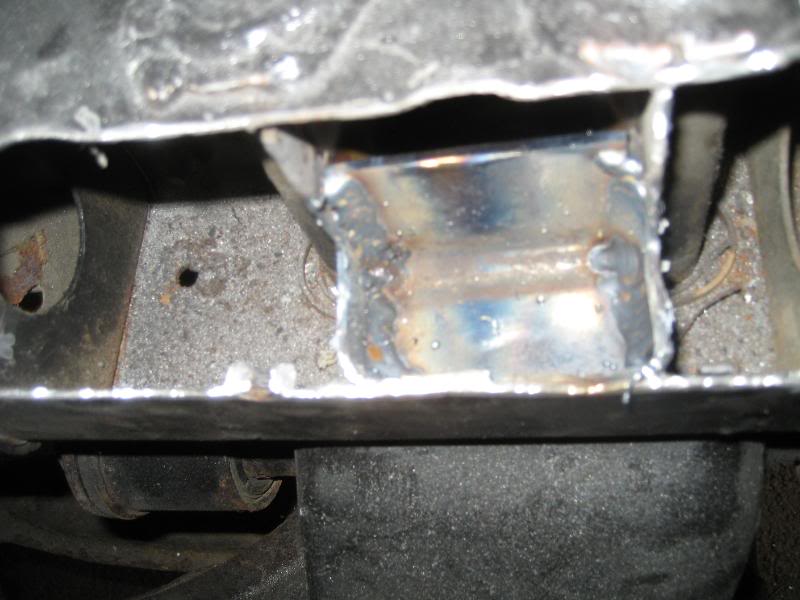
I ditched the original bracket idea for the frame notch as I was thinking and I don't want to have to worry about it breaking, so I cut out another piece of channel to fit in between the bolts for the k member (all the way to the right) 2 of the 3 "squares" are end plates for the big angle bracket, and one is for the rear antenna hole. Here is the antenna hole welded up
it cleaned up pretty nicely with the grinder
Since I no longer have the PPF, I needed some way to hang the wire bundle that used to mount directly to the PPF. I cut out 4 pieces of square tubing and welded them to the upper inside of the transmission tunnel, like so:
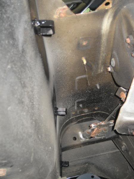
I'll either use a hose clamp or a zip tie to keep the wire tucked up nice and high and out of harm's way.
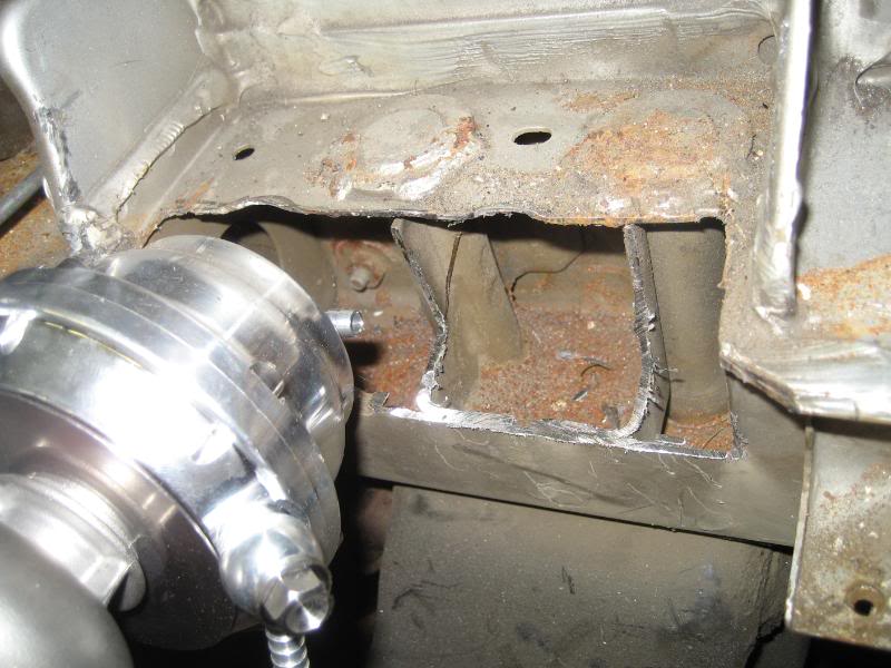
Now on to the main event. Here is what I am working with. I cut out this section so that I wouldn't have to modify the manifold.
Reply
0
0
08-26-2008, 11:28 PM
#116
Senior Member
Thread Starter
iTrader: (9)
Join Date: Jun 2007
Location: NH
Posts: 1,013
Total Cats: 21
Next I got out the dremel tool and cleaned up all the weld surfaces so there would be a good surface to weld on.
Here is a shot of the support gusset. It is welded on 3 sides. The welder tip was too large to get to the side facing the motor, but it should be plenty strong.
Here are 2 end plates burned in and the big angle bracket tacked in place
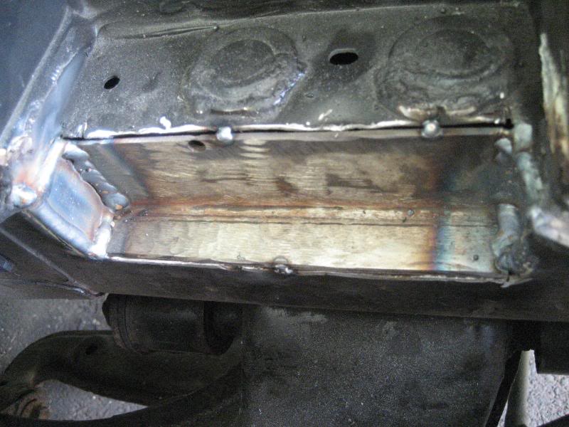
and all burned in...
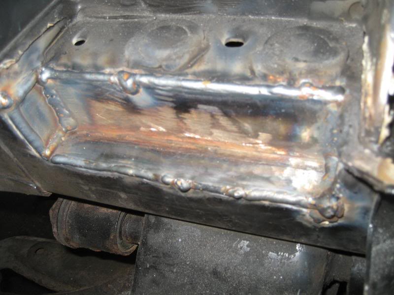
Well a little time with the flap disc on the grinder to smooth the welds out and some paint and I am good to go! I'm planning another big weekend for the car this weekend so I'll have more updates to follow. I'm on the downward slope now!
Here is a shot of the support gusset. It is welded on 3 sides. The welder tip was too large to get to the side facing the motor, but it should be plenty strong.
Here are 2 end plates burned in and the big angle bracket tacked in place
and all burned in...
Well a little time with the flap disc on the grinder to smooth the welds out and some paint and I am good to go! I'm planning another big weekend for the car this weekend so I'll have more updates to follow. I'm on the downward slope now!
Reply
0
0
 08-27-2008, 11:48 AM
#119
Senior Member
Thread Starter
iTrader: (9)
Join Date: Jun 2007
Location: NH
Posts: 1,013
Total Cats: 21
If I had to guess I would say that there are studs that run through them, almost as if those braces are sleeves, and the studs have "hats" that are welded to the top (the part that you see)....but I'm not really sure. It kind of looks like the sleeve is the only thing there as it has the large "washer", but I don't think that would be strong enough by itself which was where my guess comes into play.
Reply
0
0
09-03-2008, 10:17 PM
#120
Senior Member
Thread Starter
iTrader: (9)
Join Date: Jun 2007
Location: NH
Posts: 1,013
Total Cats: 21
swung by the car tonight and picked up the camera. Here are a couple of the pics I took this past weekend.
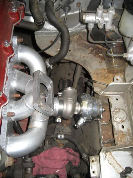
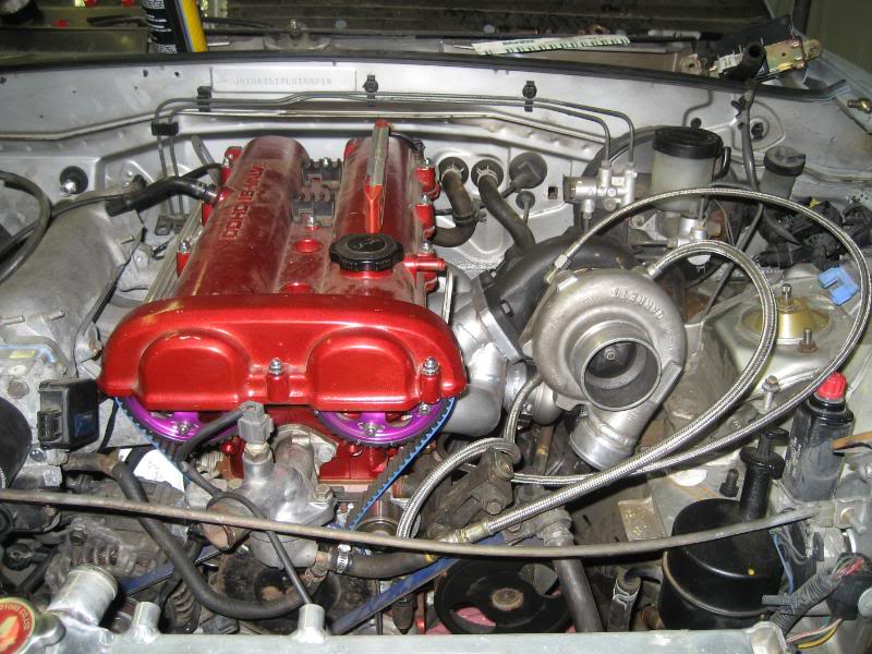
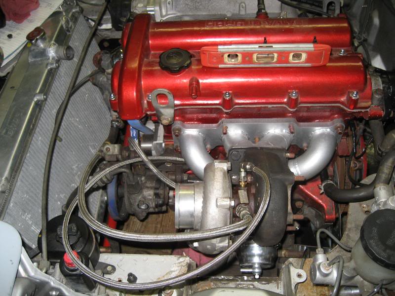
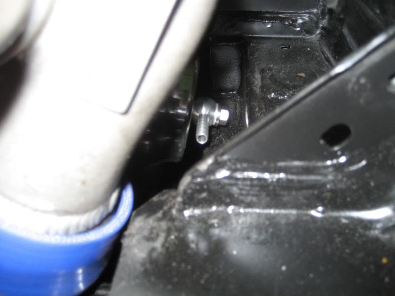
Took the cover off, and started installing components. First up was the manifold, wastegate, and turbo to see if all my hard work actually paid off.
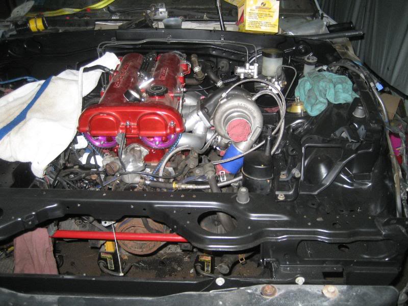
Oh and it sure did!
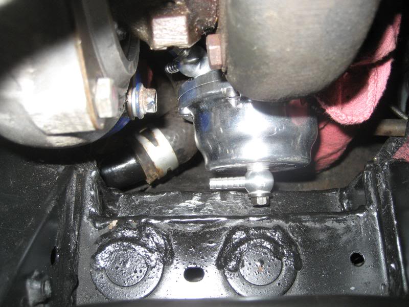
The wastegate will sit about 1" further back as the engine right now is leaning forward a bit. I'm pleased with how it came out though. Here's a shot from up front.
Next up I decided what the hell, I'm going to hide some of these wires and remove the ones I don't need. I'm doing everything else, why stop here?
I started with the passenger side as there is more junk over here. I moved the transistor and the capacitor to outside in the upper fender, drilled new holes for them and extended the wiring harnesses for them. I might go back and change this around some, and incorporate the stock bracket, but I have to think it over some more.
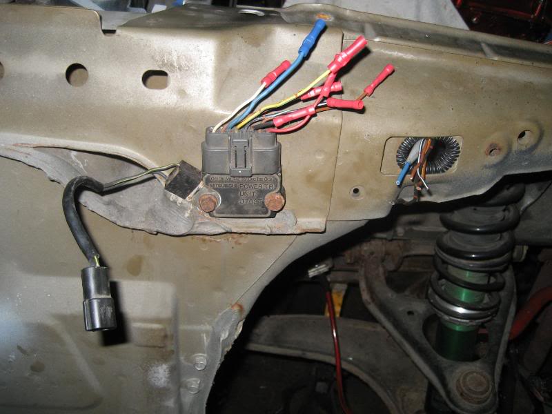
Yes, I cut off the butt connectors and soldered everything in nice and clean. I don't want to have to guess about faulty wiring splices so I figured do it right the first time. Here's a shot of them all buttoned up
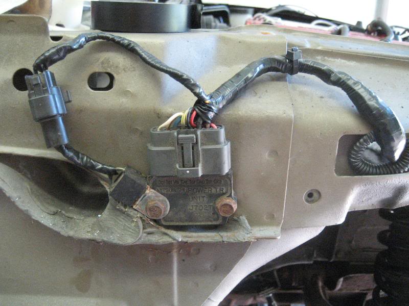
Here's the wiring after I took off the factory tape and plastic covering
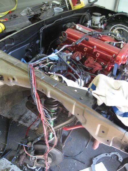
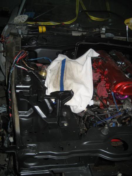
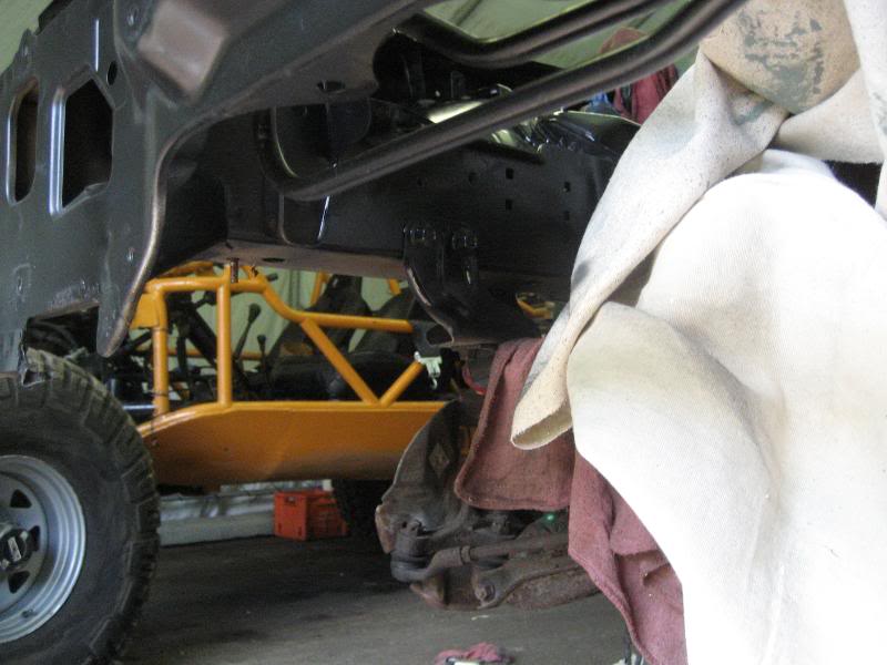
I'm keeping the towel down so I don't scratch the paint while I'm moving things around.
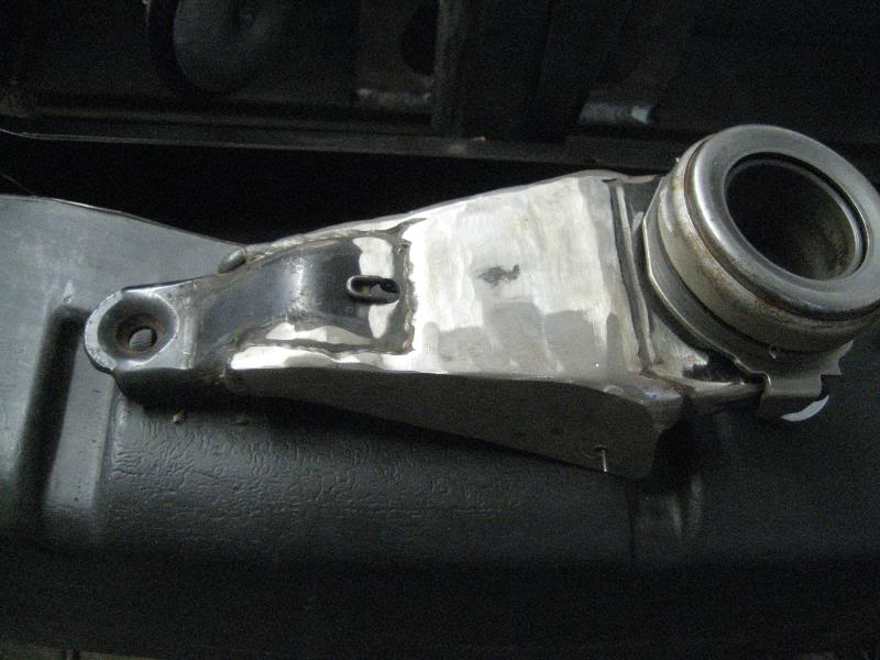
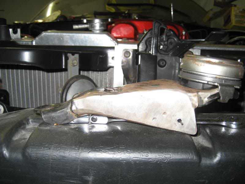
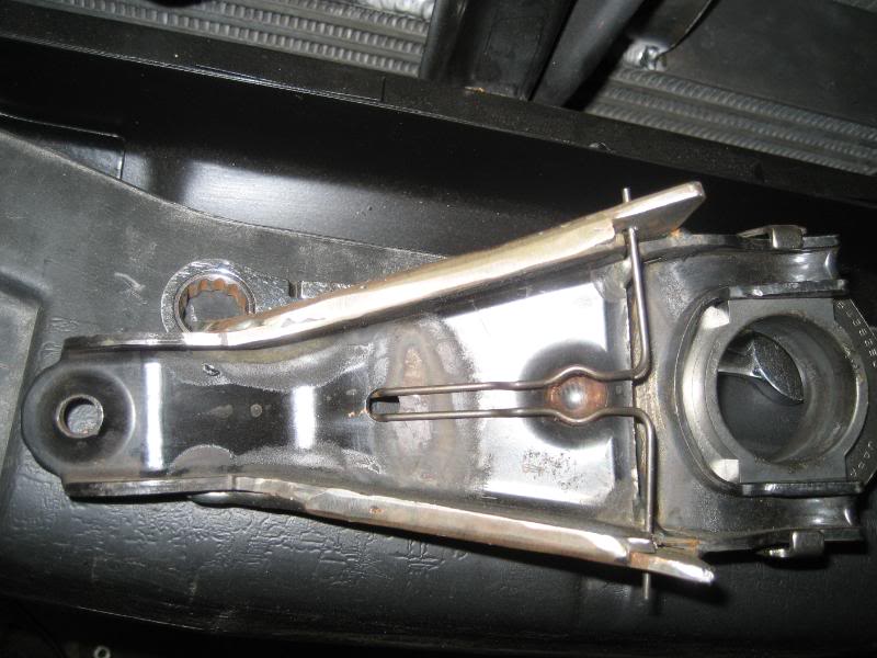
Got a little bored with this and decided to get back to fab work and finally finished the last big hurtle- the clutch fork. Unfortunately I forgot to take pictures during the process- just kind of got in the zone and saw the finish line up ahead. What I did was cut it just below the "line" below where the pivot ball sits, and spaced it out 1/2". I then cut out a piece of 1/8" stock in the shape of a parallelogram and welded it up at an angle, resting it on the pivot ball indent. I then cut out some side plates out of 1/8" stock and welded them to the each side. Here are some pics while I was cleaning up the welds with the grinder a bit.
Took the cover off, and started installing components. First up was the manifold, wastegate, and turbo to see if all my hard work actually paid off.
Oh and it sure did!
The wastegate will sit about 1" further back as the engine right now is leaning forward a bit. I'm pleased with how it came out though. Here's a shot from up front.
Next up I decided what the hell, I'm going to hide some of these wires and remove the ones I don't need. I'm doing everything else, why stop here?
I started with the passenger side as there is more junk over here. I moved the transistor and the capacitor to outside in the upper fender, drilled new holes for them and extended the wiring harnesses for them. I might go back and change this around some, and incorporate the stock bracket, but I have to think it over some more.
Yes, I cut off the butt connectors and soldered everything in nice and clean. I don't want to have to guess about faulty wiring splices so I figured do it right the first time. Here's a shot of them all buttoned up
Here's the wiring after I took off the factory tape and plastic covering
I'm keeping the towel down so I don't scratch the paint while I'm moving things around.
Got a little bored with this and decided to get back to fab work and finally finished the last big hurtle- the clutch fork. Unfortunately I forgot to take pictures during the process- just kind of got in the zone and saw the finish line up ahead. What I did was cut it just below the "line" below where the pivot ball sits, and spaced it out 1/2". I then cut out a piece of 1/8" stock in the shape of a parallelogram and welded it up at an angle, resting it on the pivot ball indent. I then cut out some side plates out of 1/8" stock and welded them to the each side. Here are some pics while I was cleaning up the welds with the grinder a bit.
Reply
0
0


