When you click on links to various merchants on this site and make a purchase, this can result in this site earning a commission. Affiliate programs and affiliations include, but are not limited to, the eBay Partner Network.
It's been absolutely hectic, the first test day is on May 6, so there's no time to rest. I wanted to share a quick update nevertheless.
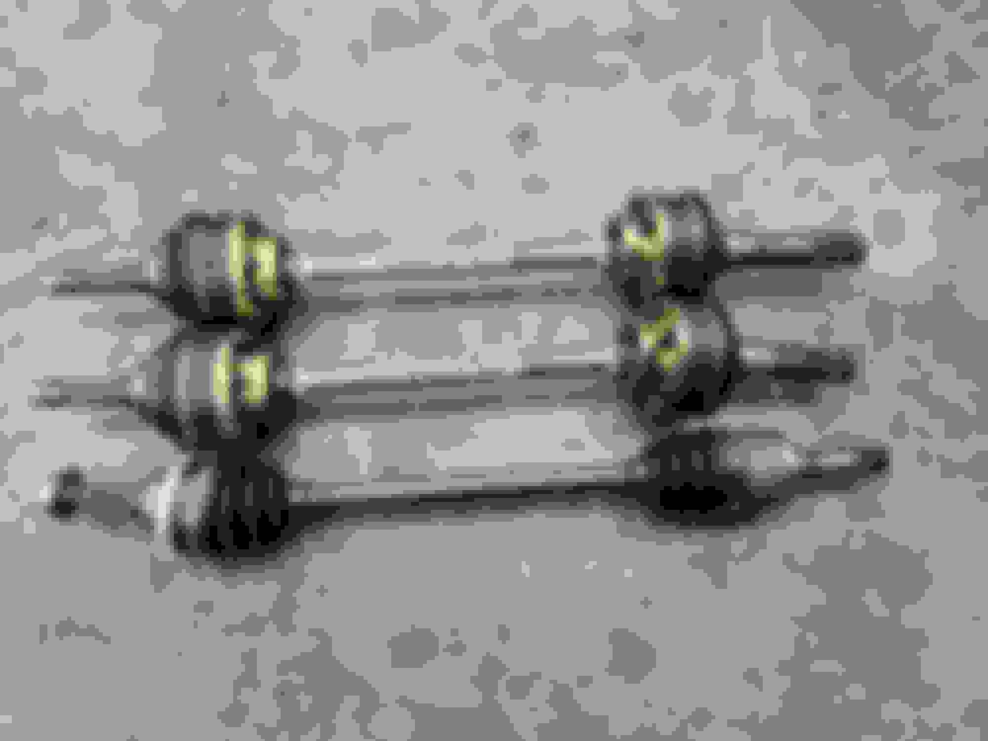
The diff is in the car. Bronson (BroFab) has finished building the axles, and I should have them soon.
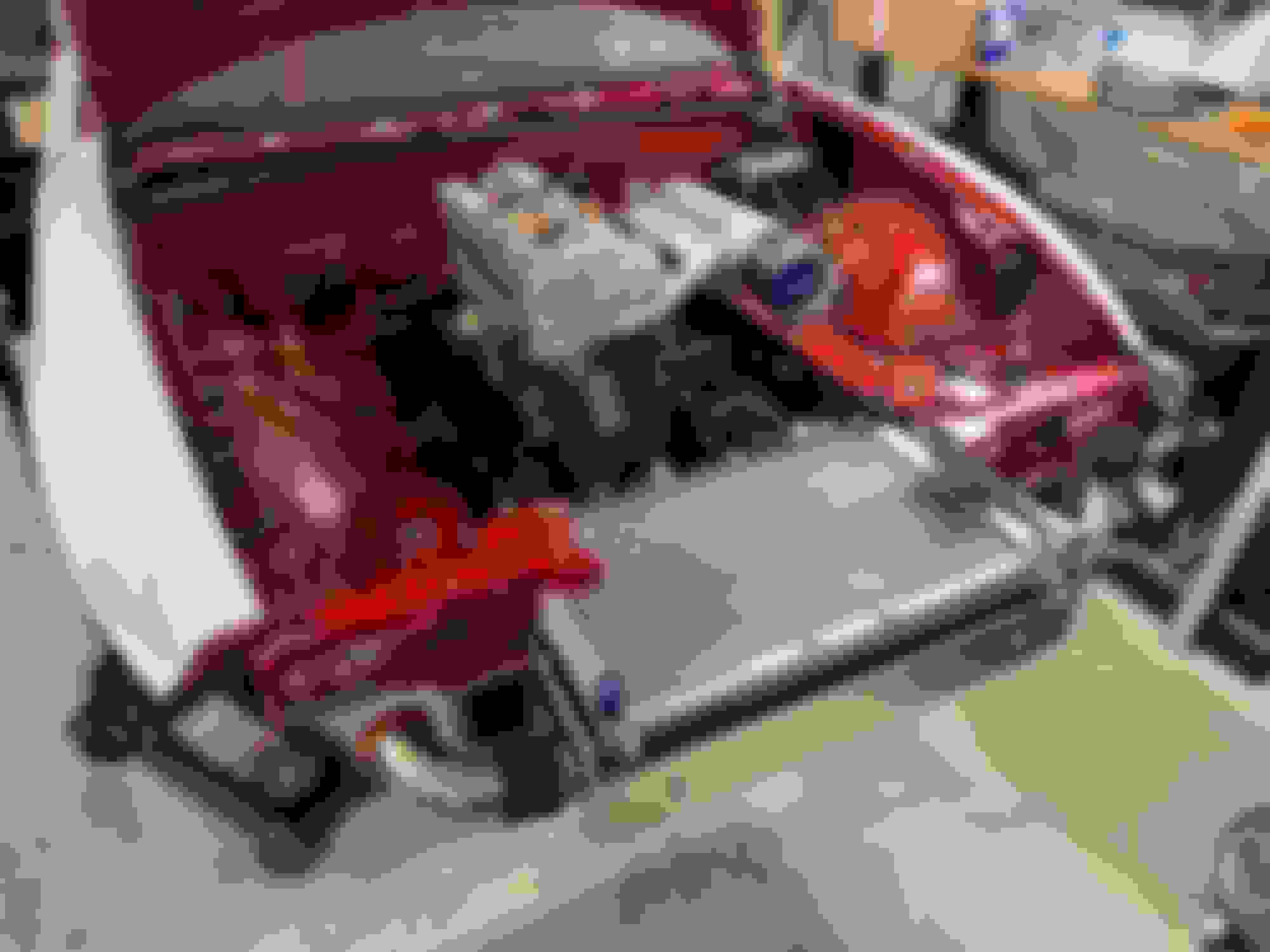
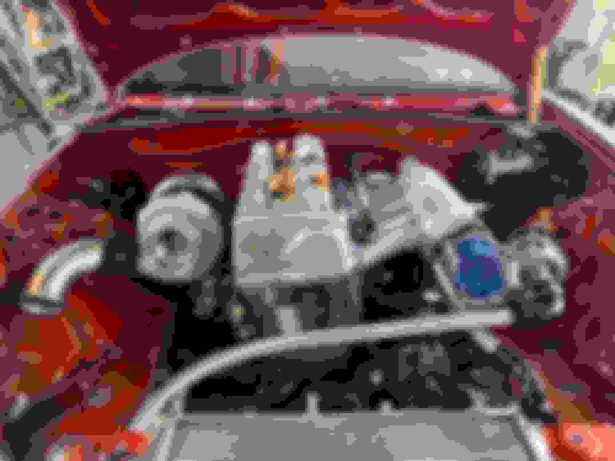
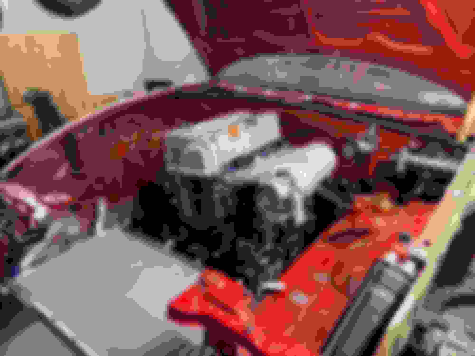
I'm still trying to figure out the driveshaft situation, so in the meantime I started mocking things up in the engine bay. Currently figuring out fittings and hoses that will be necessary, and also all the small bits for the engine (oil cooler, turbo feed/return, coolant lines, etc). The parts for the exhaust manifold are also coming, so it's gonna get pretty busy in there real soon.
On the electronics side, I'm still removing all the old stuff, so I can figure out how to mount all the new stuff. Got the CanTCU last week, and will making some mounts for these nice paddle shifters.
Another quick update: I've been slowly putting together/planning out the engine bay. It's getting pretty tight, specially since I want to keep everything above/within the frame rails to have more freedom with the aero, but it seems like it will work! Most things are laid out:
- Nuke Performance fuel pressure regulator, flex fuel adapter, fuel rail and AN8 PTFE fuel lines
- Speeding/Hurricane expansion tank and AN16 hoses
- T7Design electric water pump adapter
- Supermiata radiator, which will get some AN16 bungs welded to it, plus the filler neck deleted
Still needs to be installed:
- Intercooler, just arrived yesterday, need to be put in place
- Davies Craig EWP150 water pump
After that I can finalize the location for the hoses, catch can, water pump, intercooler piping, etc. This will also allow me to work on the radiator exit duct.
With the diff in place, I finally got all the measurements needed for the driveshaft. Bronson (BroFab) will also be helping me with that. It'll be tough to get the car ready for the first test day (May 6), but it's safe to say that without his help I would never have a chance, can't thank him enough!
II also made some progress on the hardtop. In the last picture I shared it looked mostly complete, but not every piece was properly glued together. I forgot to get a picture (d'oh), but i t now sits mostly stitched up, I just need to go over the entire thing and "finish weld" it. It also has some tension points due to small misalignments, but I'm hoping I can use a heat gun to push it back in place. I was stuck for a bit on what to do next (filler/sand/reinforce/etc), but finally decided to add a layer of fiberglass first, then filler, paint and finally use that as the positive mold for the final carbon piece. The deciding factor was that it's just too flimsy as it is (4mm 3d printed panels, 10% infill, just melted together). I'll have more updates on this soon.
As it's been the theme throughout the build, I tend to split my time between the garage and the computer, my natural habitat. I've been juggling a few different things on the 3d front:
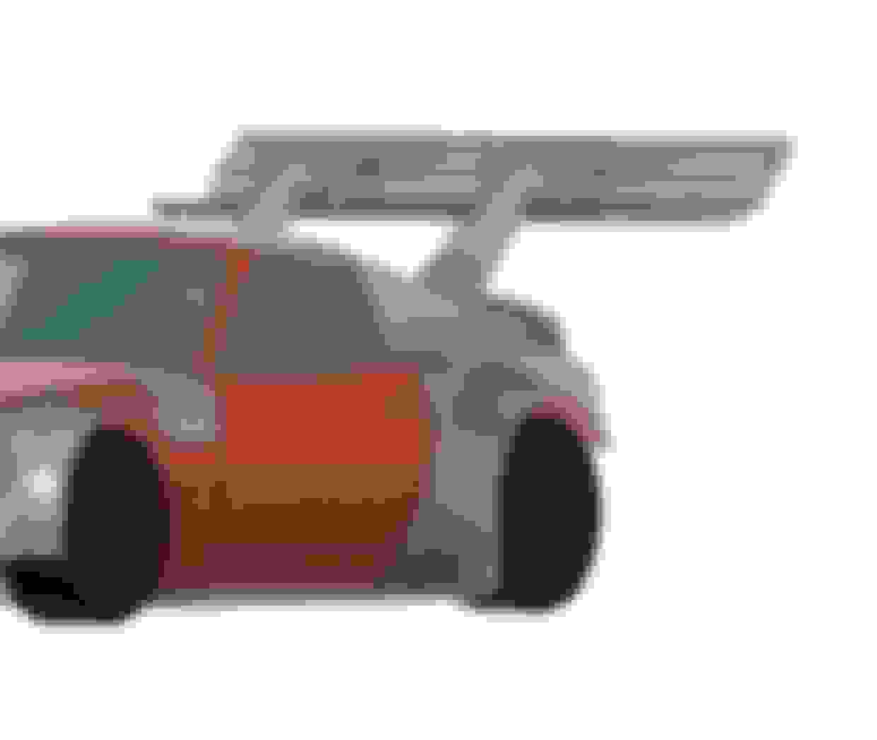
- Continued the design of the triple element wing that I mentioned last time. Worked out beautifully in freestream, ran into some issues when I actually tested with the full car model though. Made some tweaks, and it worked, but the drag penalty was just too high, so I ditched that and went back to my previous dual element design.
- Finally modeled the radiator in CFD. The results were interesting, both drag and downforce went up a bit, which I think makes sense. Drag was expected since the air is actually going through the radiator, not just making a bubble up front, and the downforce gain was small, potentially from the shape of the duct. The downside is that I don't have the proper coefficients for the radiator/intercooler combo, but should be better than a blind hole in the bumper.
- I have also been modeling the steering wheel button box, but it's not quite ready yet
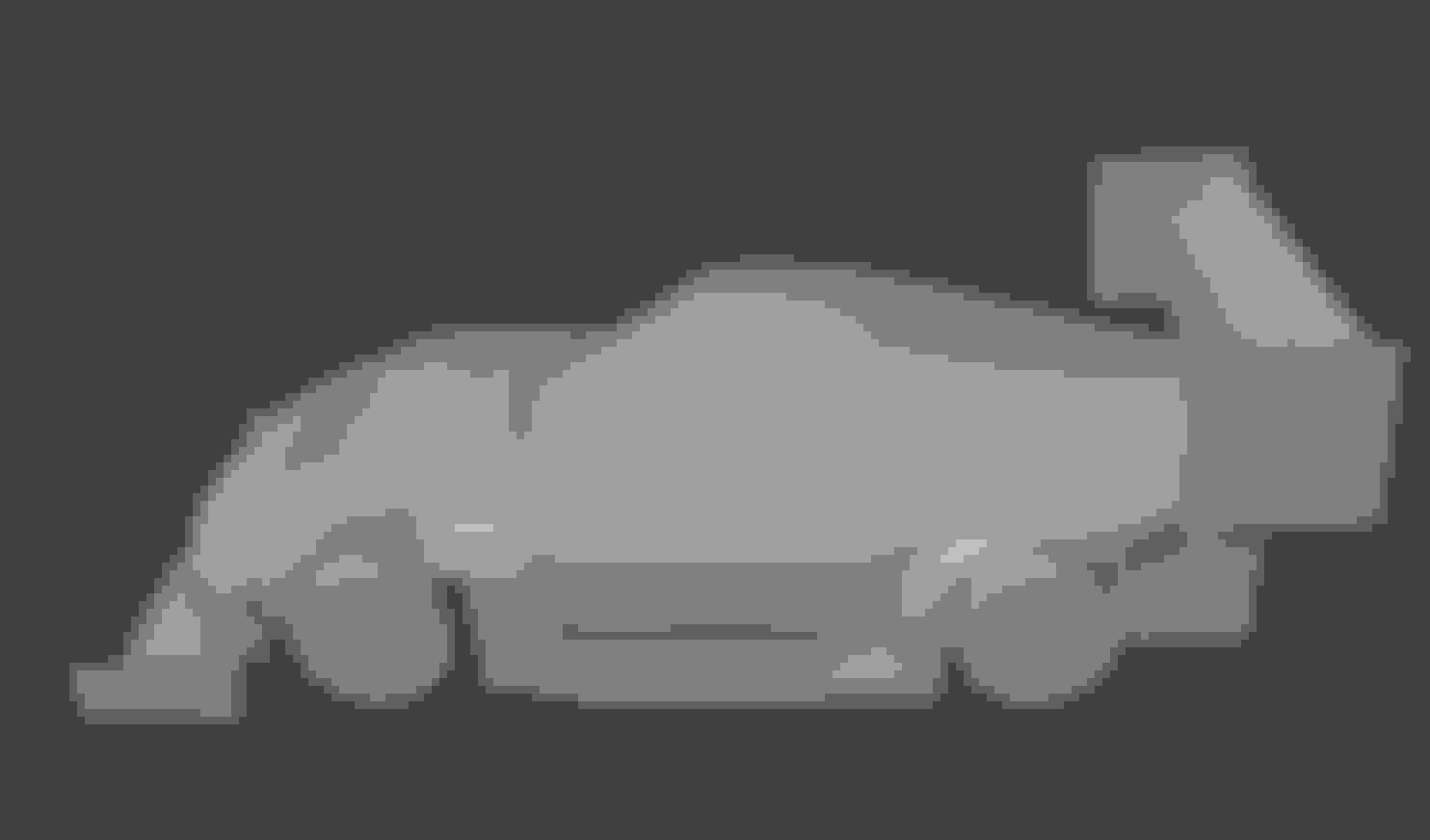
And last but not least, I designed yet another front end… so many iterations, but I'm finally happy with this one. It's not perfect, the CFD numbers could be a bit better (drag went up a little more than I'd like), but the aero balance is better, makes the car a bit narrower, it's easier to build, and I love how it looks, so I think overall it's a good compromise. Borrowed some inspiration from the Hoonipigasus, which is my favorite build ever, while keeping some of the original inspiration from the RP968. This is just a rough sketch for now, but it allows me to start building it for real! I'll clean up these shapes, work on the smaller details, and hopefully start printing soon!
Jayzuz! that 800 hp build is next level! Some rough dims, zf8-45.
lgth ~ 28.5"
bell hsg dia ~ 13.75
4" back from bell hsg face ~ 12.25 dia, but taller (dont have that dim.
8" from bell hsg face to ~ 20" from face, approx 10.5 dia
weights below assume 35 lb flyw/pp assy for manuals and same for ZF8 TC (I cheated slightly - the TC weighed 36 lbs ) and are based on quick Google for manuals, and me plus parts and bath scale for ZF8, and I assumed 15 lbs for the TC less ZF adapter. I'll try to get some pics w a tape measure so dims are a bit more clear.
Thanks as a reference, my 8hp70 weighed at 195lbs with the torque converter. The DomiWorks flywheel weighed and adapter plate together weighed at 16lbs. I didn't take any dimensions and just yolo'd it (kinda stupid move in hindsight, but I was willing to cut whatever got in the way), but there's plenty of room around the transmission as you can see in the pictures.
Not sure what you'll be doing for driveshaft, but I also ordered their 8hp <> 1350 adapter. Bronson is helping me out, we found a 1350 yoke that bolts directly to the Super 8.8 diff and a slip joint assembly.
Yep - well, I don't have it yet - it is paid for, and Daniel tells me he has just received the starter ring gear - it has been several delays but it is actually ok cuz I am not twiddling my thumbs waiting on just that - I have a big stack of parts that I am building up. And, I'm going to order the yoke from him too I think.
Every time I come to post a new update I look at the last time I posted, and every time I get a bit terrified at how much time has passed, and how little time I have before the first test day 😅
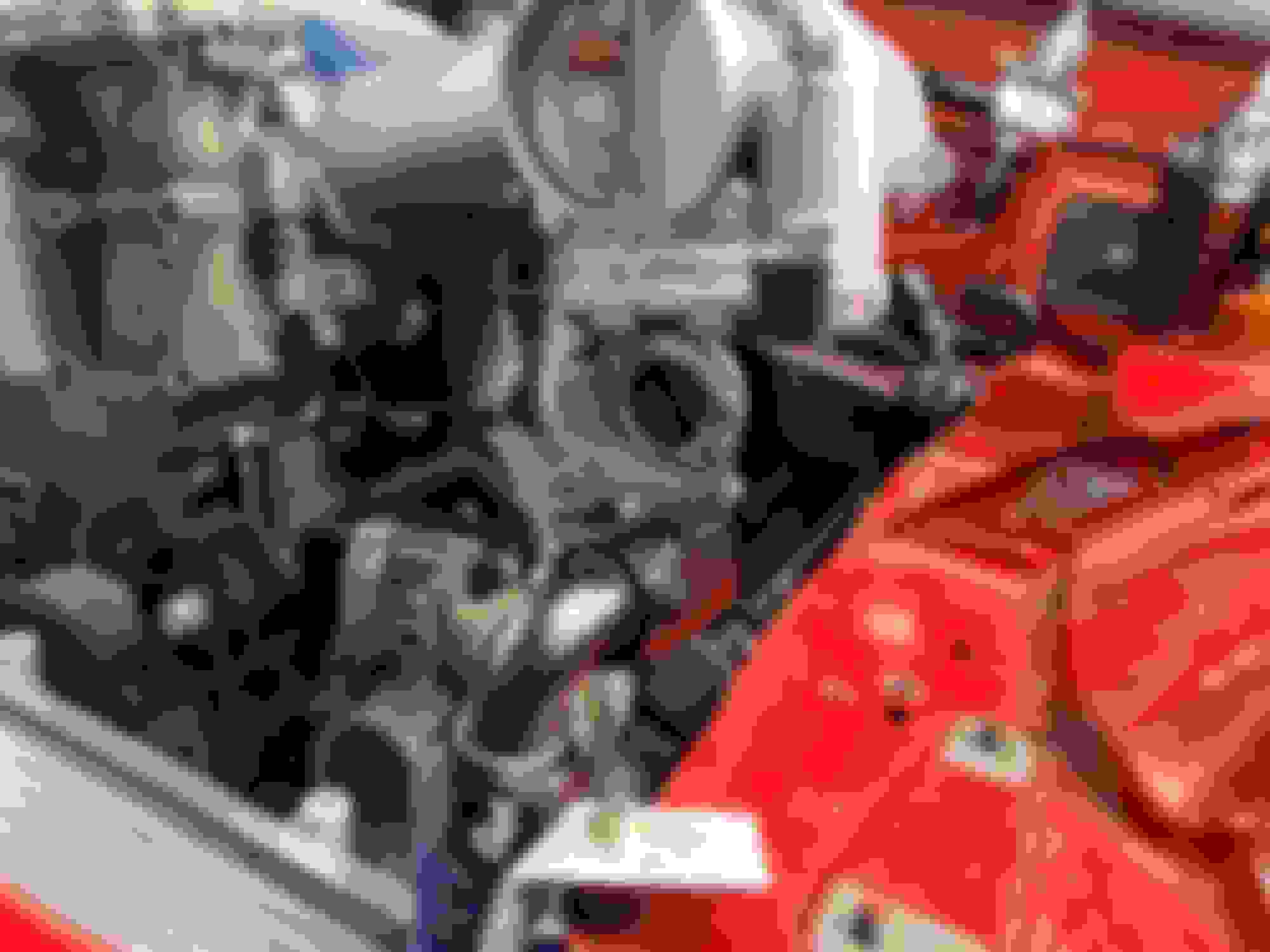
Parts continue to come in, and I'm slowly plugging away on the car. Got a large shipment from AutoGruppen, including the new ECU, injectors, tons of wiring supplies and manifold parts. The exhaust manifold will be built by AG, so I have to get this mocked up ASAP and send it back to them.
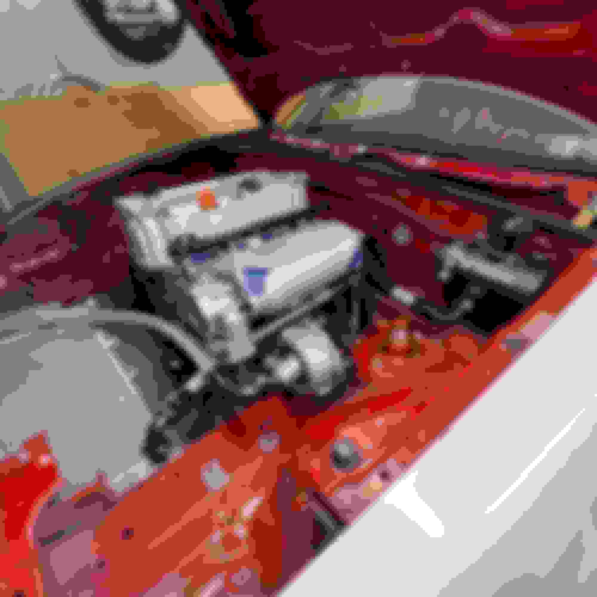
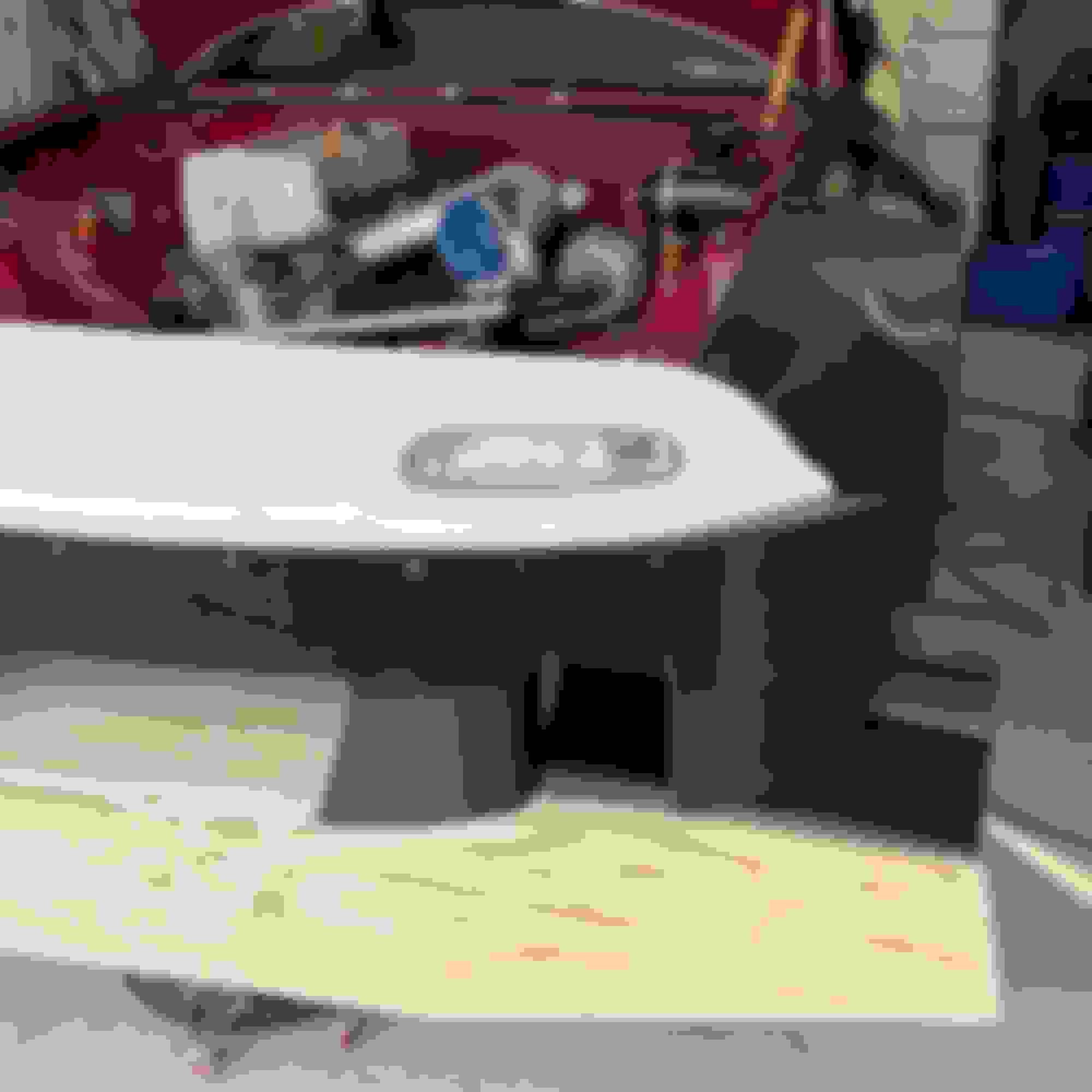
In the meantime I finished mounting the radiator and intercooler. I've also been practicing my aluminum welding, which I had never tried before, so I can weld the AN bungs to the radiator. This is the last step before I can plumb the cooling system.
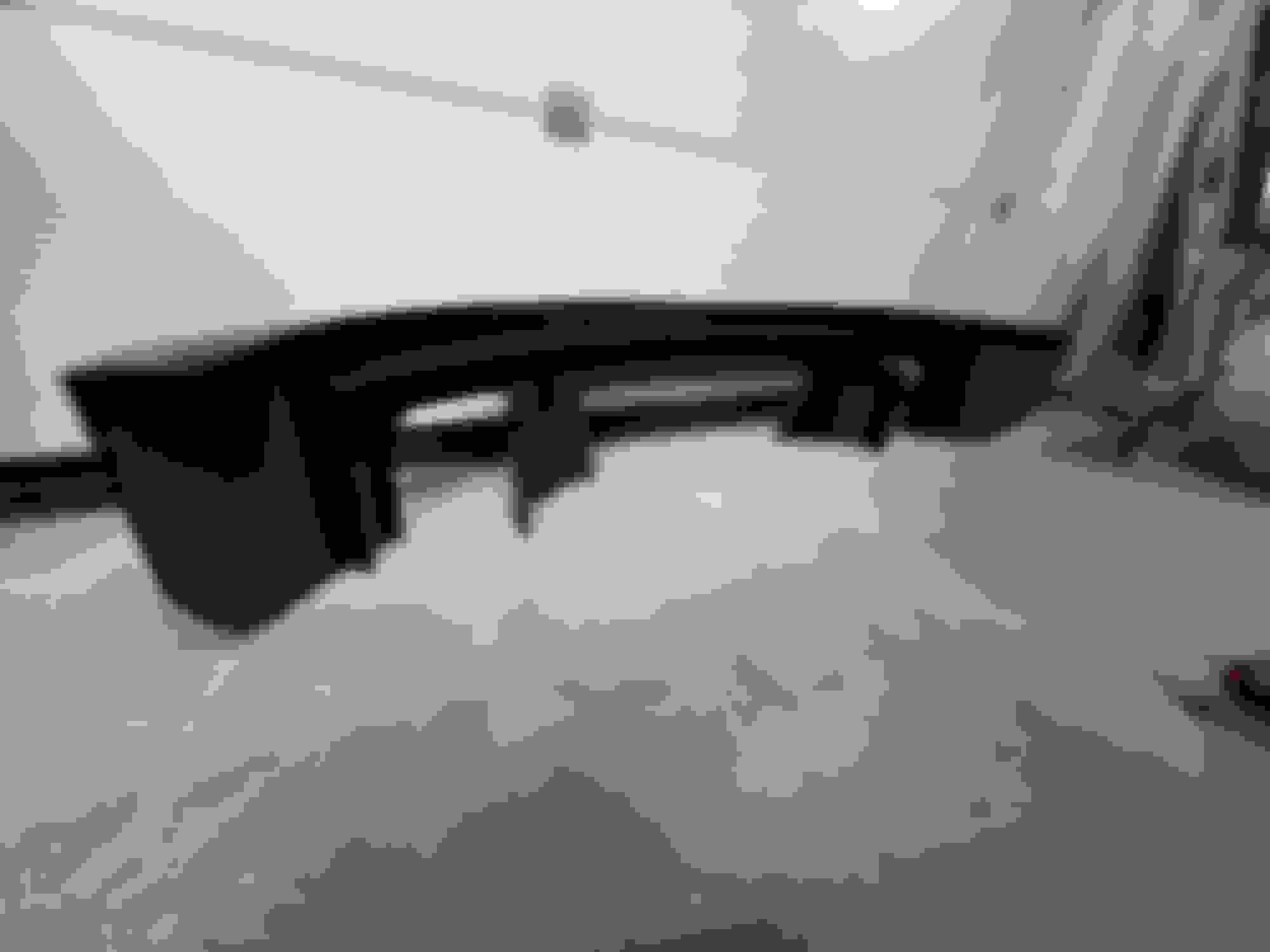
I also made the final model for the bumper, and it's already 3d printed. After learning from my mistakes with the hardtop, I adjusted the printer settings and added some flanges to the model in order to make the assembly a lot easier, and oh boy, what a difference. Completely fixed the warping issues, and everything just lined up right away. Unfortunately, we can't learn everything at once, so I didn't add any flanges to mount it to the little bit of OEM bumper that is left… it's just to be used as a mold though, so it doesn't matter much, I'll just hack something together.
The driveshaft is done, just waiting to finish balancing and Bronson will ship it out to me, so I should have it in a couple weeks depending on customs and shipping. The axles will also arrive at the same time, I asked him to hold onto them to see if it can be shipped together and save some money on shipping.
I think that's all that happened… fenders are printing right now, lots of work to finalize all the models for printing. Cleaning up, softening the lines, splitting the pieces, adding flanges, etc. The wings need even more work, sizing the spars, and making the internal structure, but that's all underway.
Next up I need to mount the electronics and get started on the wiring planning. I do like wiring, but I'm dreading the planning a little bit if I'll be honest… anyhow, no time to waste, so back to work.
That front bumper is a cool project. I'm really enjoying seeing how much 3d printers have enabled people to design custom complex parts. Excited to see what the final product looks like.
That front bumper is a cool project. I'm really enjoying seeing how much 3d printers have enabled people to design custom complex parts. Excited to see what the final product looks like.
Thanks I'm waiting to work on the composite stuff so I can focus on the critical bits for the car to run for now. I want to make sure I can get the car tuned and tested asap.
But... I couldn't resist test fitting the fender and bumper today, pretty exciting to see this slowly coming to life! While in there I also had to grab the 15x10" Dekagram and BroFab brakes to see what it'll look like 😬
Made a new render for reference, needs more work, but it's a bit closer:
Wow, this thing is already looking badass. Can't wait to see the finished product. I missed the fastback earlier. Sounds like you're printing these yourself? Any special printer or just a regular hobbyist unit?
Haha thanks, that's the goal. Printing everything myself, no special printer. Using a Bambu Lab X1C and the cheapest PLA I could find (eSun PLA+) since the prints will just be thrown away later. For the parts where the print will be used as core material (wings, endplates, etc) I will print with ASA.
A quick update, this weekend I welded the bungs in the radiator and did 99% of the coolant plumbing, but I had to move the water pump a little and ended up short by one 90� fitting. I also fit the second fender and mocked up the turbo in place, it's sitting a bit high though and it touches the hood a little, so I'll move it down a little tomorrow.
Putting this here for future recommendation in case you run into problems, but I have a lot of experience in auto industry working with electric water pumps.
Where you have the pump mounted is not the lowest part of the system. The pump outlet is pointing downward (and on the bottom) as well which isn't as ideal. It won't create issues when the system is completely bled/primed, but bleeding the system could be challenging without a vacuum bleeder considering the pump is a local high spot in the system. Centrifugal pumps like you have struggle to move large air pockets and you'll have one in the housing based on what I'm seeing.
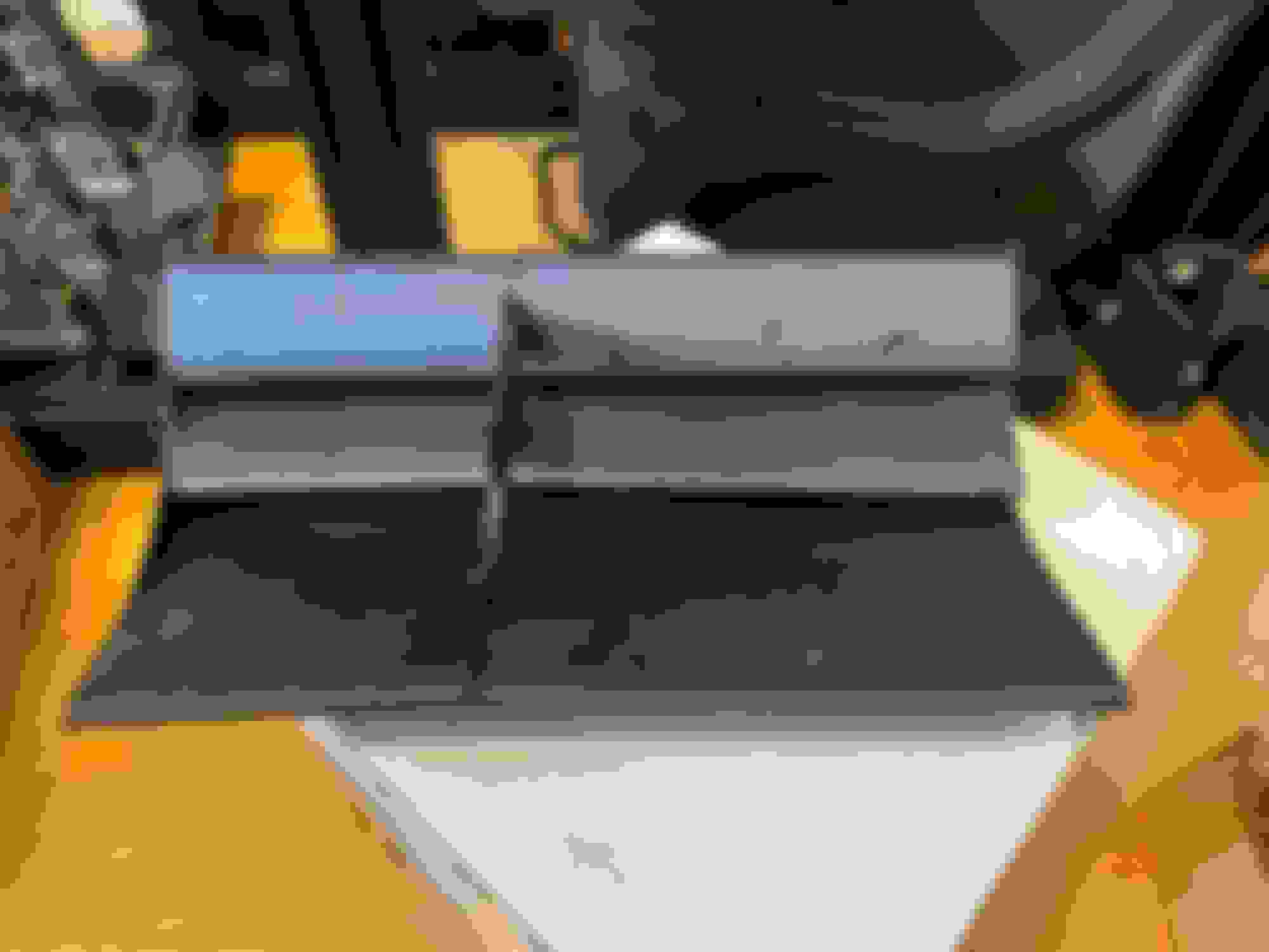
To help mitigate this, you could drill into the top of the metal pump housing and either tap threads into it directly for an NPT plug OR weld some sort of small fitting onto it to create a bleed port that can be cracked open during your fill process (location shown in blue below). A little forward thinking now like this will save piles of frustration later.... trust me...
As long as I'm on the topic, I'm speculating that the EWP150 that you are using may not hold up to the long term power levels you are targeting as far as flow rates are concerned. I can't say this with certainty until you get some testing in, but refer to this flow chart that I quickly found online that compares the Pierburg CWA400 (pump used in multiple high end BMW's) to the EWP150. I would keep a "CWA400" upgrade potential in your back pocket if you run into cooling system challenges as it will flow quite a bit more. Pump manufacturers typically rate pumps off peak flow possible, but that's a bit deceptive because in the more commonly used areas of the performance curves, these pumps (even if rated the same peak flow) can perform wildly different from one another.
Thanks for the pointers. I know the final location is pretty bad, and that wasn't my plan at all... I had read through all this stuff, and wanted to stuff the pump lower, between the subframe and the engine, that way the inlet would be pointing towards the engine and the outlet would be at the top and pointing forward, but there was just not enough space. Because of the aero design everything has to be between or above the frame rails, and on top of that all the hoses are super short (the inlet hose is 3" long, ~6" with the fittings) the fittings had to be perfectly aligned, so after many hours staring at it that was literally the only place I could find that worked.
I looked at the pieburg, but after talking to some folks running the EWP150 I was hoping it would be enough, and considering the ease of installation and price, I just went for it. But like most of this project it was mostly based on hopes and dreams 😅. I'll report back how well it works on track, and I'll consider tapping the bleeding port as you suggest, but I'm a little worried about ******* it up though haha. And considering how the radiator bung welds turned out, I think I probably shouldn't weld on it lol.
- I lowered the turbo into its final position, so it no longer hit the hood. Then I mocked up the wastegate and built up a little jig that's now on its way to AutoGruppen so they can build the turbo manifold.
- I also mocked up the front wing and splitter. The wing for the other side has already printed, I should be able to assembly it soon.
- modeled the rear wing assembly. I was printing some test pieces, but had some printer issues… at this point I have about 2 weeks worth of printing queue up, so that was unfortunate. But I hacked the broken extruder together and it's back up and running. It'd be nice to get a second printer though, I might try to a find a sponsor in that area, considering how much of the car is printed lol. I should have the test prints this week, then will send out the ribs, uprights and assemblies to be laser cut.
- Today I also received and test fit the driveshaft and axles. It's wild to work with someone across the world, Bronson built everything built and shipped here, I took it out of the box and it just fit right in like a glove! As far as we know, this is the first Miata running a Super 8.8 diff in the world.


 3
3


 as a reference, my 8hp70 weighed at 195lbs with the torque converter. The DomiWorks flywheel weighed and adapter plate together weighed at 16lbs. I didn't take any dimensions and just yolo'd it (kinda stupid move in hindsight, but I was willing to cut whatever got in the way), but there's plenty of room around the transmission as you can see in the pictures.