When you click on links to various merchants on this site and make a purchase, this can result in this site earning a commission. Affiliate programs and affiliations include, but are not limited to, the eBay Partner Network.
I'm waiting on my valve cover plans to come together, my accessory belt(s) to arrive, and I need to go steel (haha get it?) a strand of safety wire (okay now you should get it) from a friend to finish the heater port adapter. So with that stuff I have hit a wall with the motor but I feel ready to start tearing my car apart.
Fun surprise I found after tearing off the undertray: A nice little slice in the lower radiator hose on the BP from the driver's side upper control arm washer. I could see that causing issues.
Got the injectors back, here's a sample of the paperwork. Freshly cleaned and nice new o-rings on everything. $20/injector! Wonderful value and good for peace of mind in my opinion.
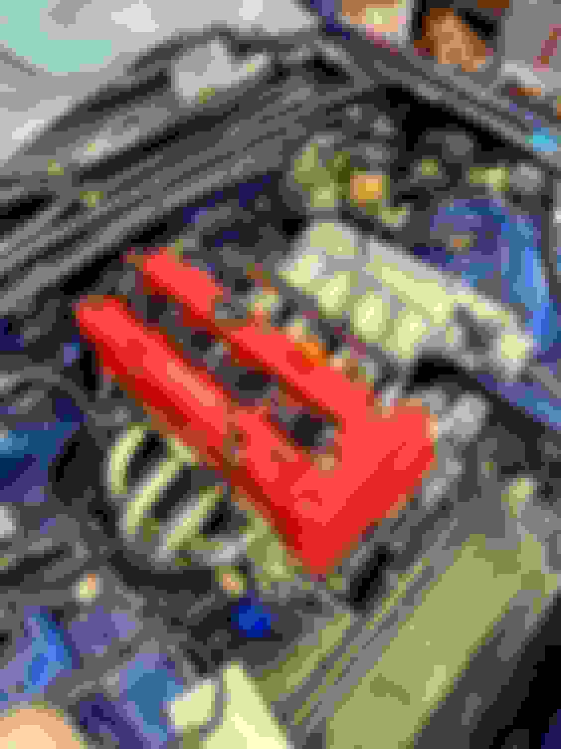
So I took my old gross valve cover and after spending about 15 minutes getting it cleaned up...
...I realized I am really lazy so I ordered this red powdercoated one off eBay. Seems nice so far.
I got this belt (Dayco 5060420) from the suggestion of another MT member's build thread where he said it works with the JDM crank pulley. Mine seems to be adequately tensioned with zero washers on the alternator so I am gonna leave it. Bonus point is that it was only $3.20 from RockAuto. Note that it is a 6-rib and these are 7 rib pulleys. I guess theoretically the ideal part number would be 5070420 (7-rib, 42" length). There does appear to be a 5070425 which would be half an inch longer than my belt, I would imagine that should work with some washers?
I began unplugging things in the car. Got the full exhaust removed and listed for sale. Coolant is drained and the radiator is being replaced with a Supermiata unit.
I was going to start removing all my control arms and bushings this weekend to prepare for my new bushings to arrive but unfortunately they have been delayed until late April, which might be after I get the K going, so depending on how my timeline moves along I might just have to do the bushings down the road.
I started by dropping out the stock subframe and installing the KPower one.
As you can see, I had to start the drivers side bolts and then ratchet strap the entire thing together to get the passenger side mounts to line up. Based on some old build threads I've read, this seems to be pretty common on V8R subframes. A note in the instructions would have been nice but whatever.
Time to get the motor ready to throw in.
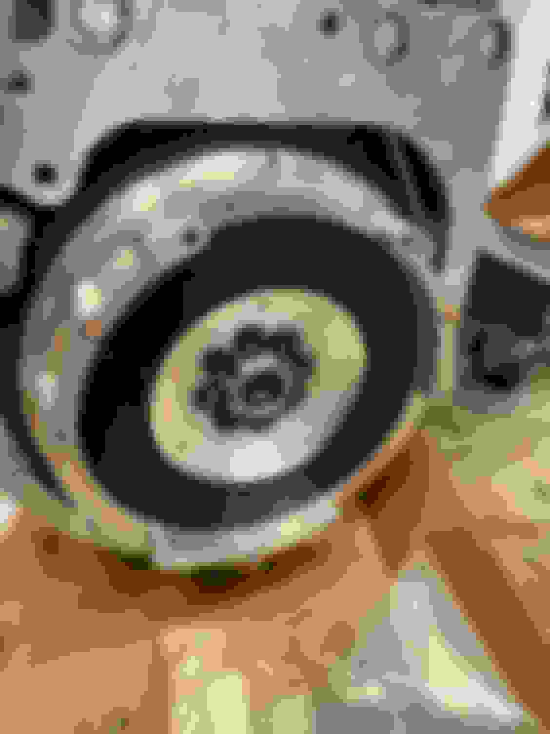
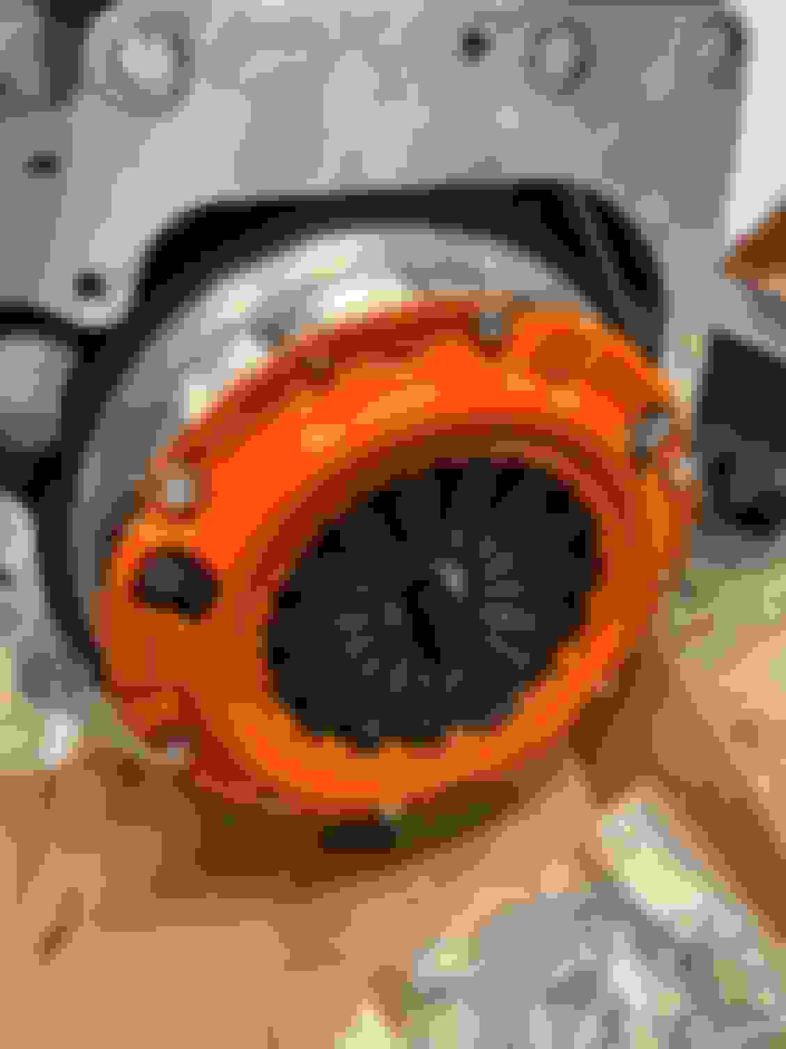
And then throw my brand new bright orange pressure plate o- oh, my flywheel didn't come with any pressure plate bolts.
Okay, an hour round trip to the store to grab some bolts.
Alright now it's time to- oh, the provided bolts are higher grade? Alright, another round trip to an even further hardware store to get the high grade bolts.
Alright, let's do the thing to the thing. 2" holesaw obtained.
Let's take a quick (4-6 hour) break to remove the entire interior (this sucks by the way).
Interior removal casualties include one aftermarket temperature gauge and both sides of A-pillar trim.
Alright now that I have people helping me let's throw the gearbox on the engine! Of course there is a variety of M12 and M10 bolts and washers included with zero instruction on what goes where, that's on you to figure out. I threw a washer on each of the longer M12 bolts and they had perfect thread engagement. The M10s are all flange heads and don't need a washer. Threw the remaining shorter M12s with one washer each on the remaining holes and start to torque things to 60lb-ft and oop-
****, alright, lets pull off the transmission (damnit) and evaluate the damage?
Alright so we've got one hole with stripped threads and two others with what appear to be very galled threads.
I wonder how that happened?
Ah, all the short bolts are about 5mm too short. Even if I skip the washer, that still isn't full thread engagement. This is a 12mm bolt into a 0.5" plate, so ideally I would want these bolts to be as close to flush as possible. I didn't even think to skip washers as every other bolt was either a flange head or was good with one washer. Note that all the stock transmission bolts are flange head. It would make sense to me that the supplied bolts should be longer than necessary so you can just add washers to get full thread engagement given how thin the adapter plate is.
Bonus points for this washerless M10 on the bottom that is also clearly too short. An adjacent M10 was the same way.
So anyway, I have a helicoil kit on order so I can repair the damaged threads and I am going to be checking a few hardware stores for three M12x1.25x45mm bolts and whatever length those M10x1.25s need to be in order to get proper thread engagement.
I did contact KPower who were very timely in their reply. In essence, I was told:
1. Don't use washers on the M10 bolts (sorry this isn't mentioned in the instructions).
2. 60lb-ft is too much torque for those M10 bolts, aim for 40lb-ft.
3. If I'd like to, I can mail my adapter plate in to be helicoiled.
To which I would be inclined to think:
1. The M10 bolt in the picture has no washer on it and I would say at least half the thread is unused. I am sure if I tried to torque that to spec it would strip out. Why supply M10 washers in the bag labeled "Transmission Side" if we aren't supposed to used them at all? Maybe mention this in the instructions?
2. 40lb-ft is below the minimum torque spec for the bellhousing bolts. If you want people to torque the bolts to less than factory spec, maybe mention that in the install guide? If you are wondering what the install guide says in regards to the entire transmission bolting procedure, it is "Install the supplied M12 and M10 bolts from Bag 2 to secure the transmission to the adapter." That's it. Nothing about what goes where, nothing about skipping washers in certain spots, nothing about torque values.
3. I ain't got time for that.
You are certainly free to argue that some of this should be common sense like checking thread engagement but for the coin this stuff costs and the fact it has been on the market for years, I didn't even think twice to look around the front side of the plate while torquing bolts or the fact that they're gonna strip out. Feel free to call me an idiot, everyone is entitled to their own opinions.
So anyway, the day that was supposed to be dropping the motor in has now been delayed so I can go drop $100 on a helicoil kit, drill bit, and correctly sized bolts. I'm sure some of you are in the camp of "well you are already spending several thousand dollars on the swap kit, what's another hundred?" but some of you may be in the camp of "I would expect a several thousand dollar swap kit to be thoroughly engineered and have clear instructions to avoid issues like this."
Anyway, that's my rant, hopefully someone can learn from my experience. Maybe there's enough variation in bellhousing thickness to account for mine being strangely thick. Hopefully the car is as fun and worth all the trouble as everyone described it to be.
You're not an idiot. I had my own gripes with their instructions, but as I peiced my kit together from a few different places I couldn't really gripe about it.
I remember not adding washers to several of the trans bolts, so far no issues from that area, even when removed and inspected.
The threading is less then ideal, but honestly not a huge issue. The majority of the load is in the first few threads. While yes, it would be proper for them to supply bolts that fill the entire adapter... They don't, and this baffles me. Seems like such a detail would be easy to fix.
And yes, it's worth it. Even after having a handful of kit/motor issues, I'd still 1000% take this over a BP motor.
Seems like the easy button would be flange head cap screw. Gives you the extra surface under the head and the length is measured from the flat surfrace to the end. McMaster sells class 10.9 metric flange heads in various lengths. Also sounds like KPI needs to hire a technical writer to make their instructions more clear.
As someone who has to write and review instructions for much simpler parts than what KPower sells, I can't even imagine it. Not excusing it, but man what a task that would be.
Hopefully you get it all figured out. I still haven't driven a K powered miata, but i can only imagine it's good ****.
Similar issues exist in the e30 and BRZ instructions. I've grown to just install things with my own knowledge from performing other engine swaps, and refer to the instructions when I'm stuck or am hoping for reassurance. I did my first three K-Miata swaps into NA's, so since their very first instruction is basically "NA owners are on their own to find the differences", I'm used to it. Ironically, the Ecotec swap seem to have a "shade tree mechanic" vibe going for it, but after reading a lot of KPI's instructions, I certainly missed EcoTec Miata's specs for all the Miata/aftermarket/GM parts.
Personally, I'd grab a tap, oil it, and clean up those threads from the back. Grab some flanged bolts of the proper length, and I bet you'll find they'll torque to 40ft/lbs on the remaining threads.
Reminder: I also don't have a lot of time to read through all these posts like I used to, so if you already fixed this, just ignore me.
I'm sure a cleaning with a tap would have been sufficient but I ended up just doing the thing so hopefully I never have to worry about it again. I had a blast getting the tap to go in mostly straight, turning it was definitely more difficult than the M6x1.0 helicoil I had to run into my water pump housing. Threw some red Loctite on the helicoil and am gonna let it set so hopefully it doesn't budge while I torque the bolts in.
I also received the first of a few non K24 related upgrades.
So I started by making sure everything was ready to drop in. The steering rack had to be adjusted because I realized I was off a spline or 2. What ended up being right for me was the steering wheel dead ahead and 61mm sticking out of the drivers side of my rack.
Once again, I threw the gearbox on the engine and was very deliberate in my checking of thread engagement and torque values.
I had a bit of a panic moment when the middle top M12 bolt you can see just under the rear water neck above started binding pretty bad while threading in. I am guessing because the threads were galled from last weeks incident and all I did to clean them up was run a bolt through it. Myself and my friend decided that either A) the bolt strips and we have to remove the trans and adapter plate to fix it or B) it holds the torque and its fine. It ended up being B as it held 50lb-ft, but god help me when I have to drop a transmission again, I have a feeling I will be putting that helicoil kit to use again.
Of course, I grabbed the motor mount box and the bag with 14 bolts on the label and realized the bag did not contain the 6 M10x1.25x20mm bolts that attach the motor mounts to the adapter pieces, so I just dug around the garage and found 6 random rusty various length bolts that appear to be holding for now?
So in the motor went, this part was honestly a little tough to get the motor mounts to line up. You don't put them on until the motor is in the bay. We ended up dropping the engine in so the drivers side was about 1.5" below the mount and the passenger side was 6" above due to the way the load level was positioned. The motor was bench pressed into position and the drivers side was installed through the subframe. Then, we lined up the passenger side and couldn't actually get the bolt all the way through the mount, so we cracked loose the motor mount from the adapter piece until the long bolt came through, at which point we tightened up the mount to block bolts again. Ran into a short snag with the transmission to PPF bracket needing a fresh bolt and the threads cleaned up with a tap, then I did what most people suggest and shoved the tail of the transmission as high as it would go before tightening the bolts in order to get the nose of the motor down and improve hood clearance.
Started sticking the manifolds on, ran some RTV around the coolant port on the intake manifold and intake flange. Stuck the crossunder tube thing on the bottom of the header and found that it was rubbing against the oil pan.
I had my buddy crack loose all the header bolts and I got under the car and held the crossunder pipe away from the oil pan as he tightened everything again. This got me to 2-3mm of clearance between the pan and exhaust, I was told this is pretty typical?
Remainder of the interior came apart to do the wiring.
I asked a fellow K swapper some wiring questions, and he told me that he had his friend do the wiring so he doesn't know much.
I decided to carry on the torch and had my friend do all the wiring. As far as I am aware, he basically completely ignored the KPower instructions as they left him very confused, and instead followed this thread as exactly as he could. The only deviation was that my harness didn't have a second 12V switched pink wire, only the orange one. But all the splices were done inside the cabin.
Grabbed my KPower RWD harness and started matching up the plugs.
This process basically took like 3 minutes to fully connect the engine. Nice.
So now it is almost fully wired. I need to connect the starter cable, the coolant temperature sensor for the cluster, and buy an IAT because my engine did not come with one. I'm still trying to figure out how to mount the IAT since it's unthreaded. Also need to plug in the O2 sensor and wire the power harness for the oil pressure gauge.
I need to figure out how to ghetto connect the fuel line to the rail, and I think I know how I am gonna do it, just need some hose. I need to pick up vacuum line and a T fitting so I can rig up the cruise control. Breathers for the IACV and the valve cover. PCV hose into a redbull can or something. Pulled the caps off my injectors to find one of the O-rings is fudged up so I need a single injector O-ring.
Assuming the wiring was done right and can be finished right, I would guess that the engine is half a day from cranking over and starting. Once I verify that it runs, I will figure out plumbing for the coolant. I think I have the coolant figured out just from chatting with various people, and I need to figure out what to do for the intake.
When you get a silicone coupler for the intake, drill a small hole in it and push the IAT through. Can be done really cleanly with tiny hole saws if you have access to them.
Like these: https://www.eastwood.com/blair-kit-r...=google&wv=3.1
Also, make sure that ground by the coils goes to the valve cover grommet, not one of the threaded holes in the valve cover, since it's not grounded.
So I plugged in my IAT, replaced my wonky injector O-ring, threw some breather filters over the IACV and valve cover, and then extended the starter wire to the K starter. My buddy was a bit skeptical of the methodology (using a 4ga battery wire from advance and then splicing it into the miata harness using an underground splice kit that barely fit the wires with some strands trimmed off) but it seems solid and wouldn't come apart. Luckily it was barely long enough to reach the starter.
So I plugged in the ECU, loaded up the base map from KPower and it cranked!
I cranked it for 60 seconds and then connected my fuel pump power, crossed my fingers, and...
nothing!
Turns out my buddy who did the wiring just straight up forgot to wire in the fuel pump because the instructions were too confusing. We ended up running the 10ga blue wire from the patch harness directly to the battery as advised, which will need to be extended to get all the relays to fit under the dash. We ran the 10ga green from the patch harness directly to the fuel pump as well.
I had to kill it because my ghetto fuel line setup was spraying gas all over the engine (lol).
Satisfied with my progress, we called it a night.
I returned the next day and began making it more ready to run for more than 5 seconds.
Non ghetto fuel line setup with proper quick disconnects from NAPA and some high pressure injector hose.
Drilled a hole in the temporary intake and rammed the IAT through and then globbed RTV around it.
The recommended lower radiator hose was touching the sway bar. Using a tip I saw on facebook, I cut the hose just after the "S" bend and then rotated it around until I got to about 3/8" of clearance to the sway bar and then I connected it back together using a 1.25" joiner from pegasus and some Gates big *** powergrip heat shrink for radiator hose connections, **** is expensive for what it is ($6.something per?) but pretty cash money if you want to avoid using worm gear clamps all over the place.
Also, very happy to report that my hood closes and latches just fine with zero trimming to anything.
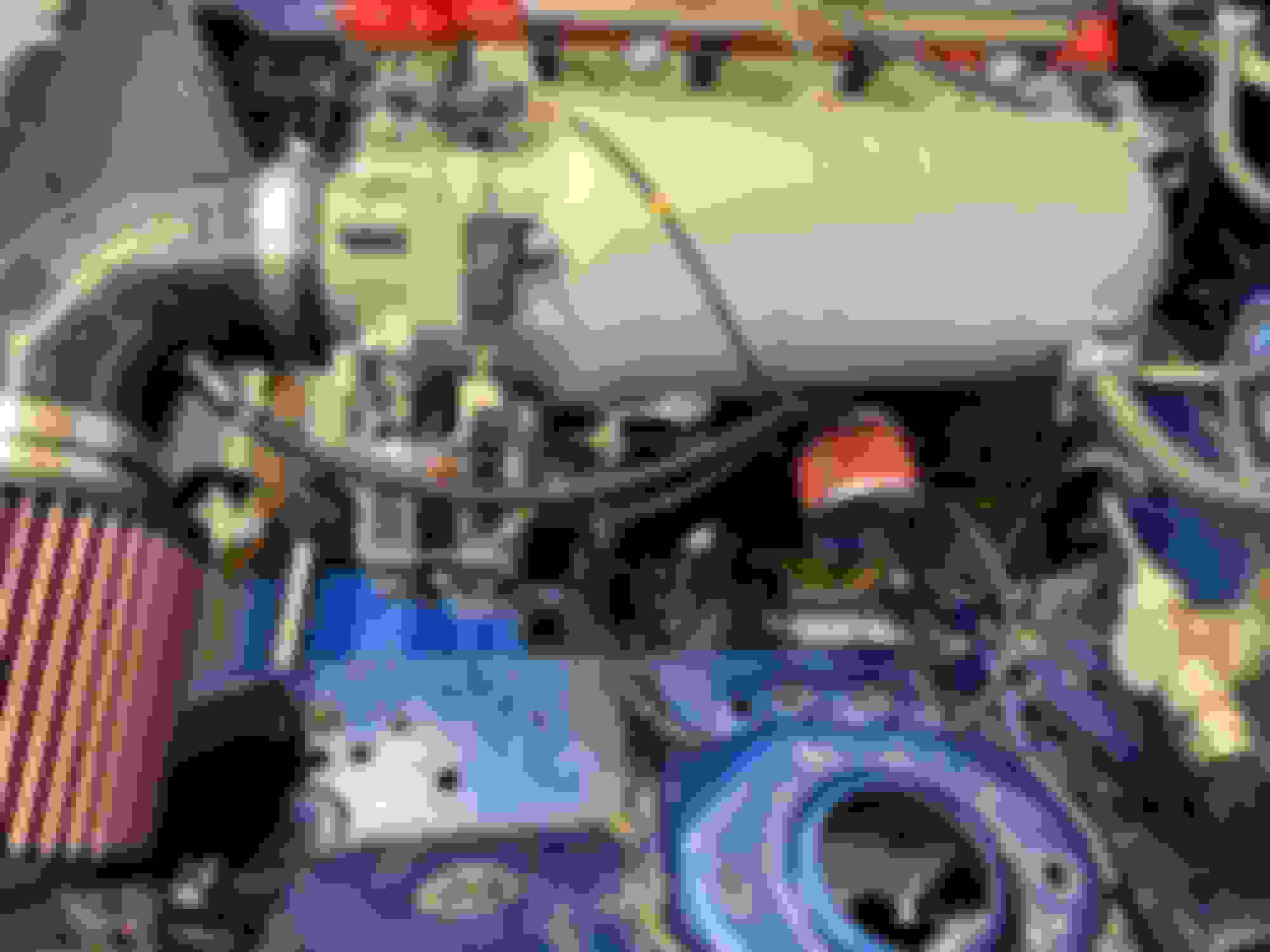
The only hiccup I have hit so far is that APPARENTLY with the old non auto tensioner belt routing like I have, you are supposed to just chop the top bit of the water pump housing off. This wasn't in my instructions, maybe because my kit was shipped right as they started recommending the auto tensioner? See below example vs. my engine bay:
Here is a close up comparison:
So basically, I have a few options that I am still weighing:
1) I can chop that thing off, probably in the car because I can't be bothered to remove it now that the engine is in. This would involve removing the intake manifold, plugging every hole I can see, covering everything I can in trash bags, and either 2" holesawing it using the bolt hole as a center point then cleaning it with a dremel, taking a jigsaw to it, or an angle grinder. The aluminum is pretty soft so I expect a quick but messy cut. This would give me the simplest, cleanest upper hose routing but would prevent me from ever using an auto tensioner without replacing the water pump housing.
2) I can leave that thing on and try to run the upper radiator hose further around the intake manifold, maybe below the air filter. This is probably doable but just makes the hose routing weirder and introduces more potential rubbing points or leak points with joiners.
3) I can do the auto tensioner belt setup ($250-$300?) and then install the passenger side coolant neck ($200) which runs the upper radiator hose BP coolant reroute style with one big long hose around the passenger side, which places it right next to the exhaust.
I am leaning towards 2) because I don't wanna bone myself later if I ever go auto tensioner.
Here is how the upper hose looks right now. I might be able to jam it through the gap between the intake manifold and water pump housing, but it seems likely to rub on everything. Under the intake might work but because of how my intake is set up it may end up close to the throttle body.
I plan on playing around with some hoses and joiners and seeing what I can figure out. I think I could get it with a longer straight bit ahead of the motor and then putting the other 6" joiner below the intake manifold to meet the one coming off the back of the head.
Before that, I would like to clean up the wiring inside the car and verify everything wiring related is good to go so I can start to reassemble the interior.
So once I have finished the K-swap, all I have left to do is a full bushing job on all the suspension arms, full hubs all around, and then my neat big brake kit I have posted zero details about.
Started the weekend by getting this **** out of the way.
It looks okay for a track car. I just wanted the glare from the shitty faux leather gone. I only did the top half of the dash. Whole process took about an hour. I had to buy a bigger brush before I did the dash because the provided one is comically small. It's definitely tricky to work that fast, you have about 10-15 minutes of stickiness on the glue so I worked up quite a sweat trying to get every surface adequately flocked in that time frame. I would recommend a helper for the painting if you want to do it.
I took care of a bunch of other little tasks. I relocated the stop for the throttle body spring because people say it reduces the TB sticking issue. I cut a small bronze bushing off the throttle cable (no mention of this in the instructions) using a dremel and then got the throttle cable mounted, adjusted the pedal so I get full travel.
I put some "asphalt coated loom wrap" on the starter wire since it is just draped across the transmission. It appears to just be cardboard with some kinda tar sealant on it, supposed to be good for 350F (more on this later). I got it for free (thanks NAPA).
Plugged in all the cables on the transmission. Put the heater core, evaporator, and blower back in the car after cleaning the nastiness out of all of them (pro tip: the blower has to go in before the evaporator).
I mounted a brand new NB2 AC condenser in the car since I do plan on reinstalling AC one day. Right now it serves as extra weight and a radiator protector.
I brought my buddy back to finish up the wiring. He wired in the temperature sensor for the stock miata cluster, extended the power to the fuel pump relay so that can sit under the dash, and put split loom on everything we could think to cover. Grounded a loose ground in the engine bay coming from the stock miata harness.
Came back the next day and went to turn on the car to verify everything works on the cluster and found zero power anywhere. 80A main fuse blown. Removed it (pain in the ***) and swapped in a spare one, which immediately blew. Began investigating things.
Remember that loose ground I found in the engine bay that I grounded to the chassis?
Yeah, I'm ******* stupid, that is the alternator charge harness for the stock miata. I didn't use it because I am jumpering the alternator to the starter with the KPower harness. I just saw random ring terminal and assumed it was a ground for the starter or some ****. I cut the ring off and covered it in a **** ton of heat shrink, loom, and electrical tape so it doesn't short out on anything. Oops.
Okay, car still starts, doesn't spray fuel everywhere, tach works, CEL works, oil pressure works. Good enough for me.
I did some wire clean up inside the car. I ended up zip-tying most of the wires to a random bracket behind the evap. I figure they are out of the way visually, hard to kick, but still accessible down the road (read: air conditioning wiring).
I am planning on running the ECU in the glovebox so that made the rest easy. I jammed the relays to be wedged between the evaporator and the sound deadening up top. Anyone see any issues with this? I don't want to try affixing them anywhere with adhesive because I know that **** will melt off and it'll rattle around. I am aware this is terrible for accessibility (remove the dash if anything goes wrong) but I don't foresee needing to touch these relays unless they blow up? Yes, there is a 30A fuse on the fuel relay wire running straight off the battery.
(yes they are actually pretty secure in there).
Mind that my dash has full HVAC so I think I am limited by space.
More wires and connectors you can see here are zip tied to a random clip that connects the blower to the evaporator. OBD2 port will sit in the glovebox for the time being.
Back to the engine bay side.
Managed to jam everything into the stock grommet with the hole way enlarged.
Oil metric wires wrapped in some more loom.
I was nervous about melting my blue gatorade tank due to header proximity (probably overreacting) so I made this heat shield from a spare square of DEI Form-A-Barrier I had. Took me about 15 minutes.
I was also worried about heat on the stock harness running to the fuse box so I bought some DEI velcro split heat shroud and wrapped that. I had some left over so I also wrapped the clutch slave line even though it's braided (more overkill?). I still had more left over so I wrapped the part of the starter wire near the header over top of the asphalt coated loom that was already on there. All the heat shield!
I was finally able to fully torque the crank pulley bolt to 181lb-ft. I adjusted both rear calipers to be extremely tight on the rotors with the e-brake, yanked the e-brake handle up, put the car in 6th, and got the big boy torque wrench until it clicked.
And finally with the crank pulley torqued I could reattach the front sway bar.
I clamped on the lower radiator hose. I am a bit nervous of clearance to the sway bar. Here is how it looks with nothing on the hose. I am unsure if I should put something between the sway bar and the hose? Anything I do jam there is gonna get rubbed on. Someone told me "1/16th is basically a country mile". Gonna try that line on the next date I bring home.
Waiting on the dash to fully cure before reinstalling it. Instructions say 72 hours to 1 week.
Waiting on some upper radiator hoses to arrive in a couple days which should let me run them under the air filter and save me from cutting any **** off the water pump housing.
I feel like the end is near but I know there is still so much to do between the suspension, hubs, brakes, teething issues with the swap, tuning, etc. I completely forgot about the PCV until I was typing this sentence. I've seen some people saying they just thread a bolt into the hole, effectively plugging the PCV, but KPower recommended against this.
I wish the thread title had something about K24 content because this build thread was really boring before.
Based on the input of a fellow K swapped NB owner I found on the internet (thanks zuckerberg!), I purchased two radiator hoses off advance:
Dayco 71387, Dayco 71994.
These two together should get under the air filter as shown below:
Unfortunately, I have a Supermiata radiator, which has the hose barb all the way on the passenger side, so that reduced my reach.
I ended up using the 71994 hose to get from the radiator to the driver's side of the engine:
Next, I stuck a 6" aluminum joiner I got from Speedway Motors (awesome retailer, by the way) on the end of that hose. I decided I was going to leave the auto tensioner part of the water pump housing intact and jam it under the intake manifold still. My thought process here is that this looks like a highly likely rub spot and I would rather have aluminum on aluminum than aluminum on rubber if things were going to rub. (slightly concerned about any coolant leaks going straight onto my brand new remanned denso alternator).
I attached the other end of the aluminum joiner to a piece of hose I cut from my old QMax reroute hose:
Finally, I used a Dayco 72098 on the rear water neck to point it around the corner and joined that to the QMax hose using a 1.25" aluminum joiner and another one of those Gates Powergrip heat shrink things:
My only concern is rubbing on things and the fact that the hose is a bit of a high point. I may fix these things later but probably not until they cause issue.
No good pictures, but for one of the heater hoses (seen above) I am using just 5/8 by the foot from the heater adapter to the driver's side heater core barb.
For the other heater hose, I am using a Dayco 80401 that I have trimmed an inch or so off each end for the water neck to the passenger side heater core barb.
I got under the car and reattached the center section of the butterfly brace. I did a quick test fit and it looks like the KPower race exhaust will clear but it's definitely tight. Will be able to give a better answer once I try to throw the full exhaust on. I reattached the rear wheels and dropped the back of the car on the ground and then left the front on jackstands. I started pouring in straight distilled water and quickly found a leak!
Phew, it was just the clamp on the lower radiator barb that had to be tightened. I poured in about a gallon and left the lisle funnel full and started the car.
I didn't photograph much but in short, I would run the car for a minute or two and the idle would keep picking up from 1400 to 2000 before I killed it. I'd go walk up front and squeeze hoses, starting with the lower radiator hose and eventually getting the top hose. After doing this for 4-5 cycles, I had warm hoses all around and I was showing 180 on the ECT on Hondata. The fan kicked on, but the water temp would keep going up until I killed it when the water started boiling. I kept squeezing hoses and eventually the car took in a lot of water and the temp started going down, so I figure by now it's mostly bled? I didn't dick with the heater core so I have a feeling the nose will be going back up in the air and I might need to play with my upper hose and push it down to get more air out.
I upped the fan temperature to 200 because 180 seems low. Any input here? I think the thermostat is 195F but I may be pulling that out of my ***. That's when it seemed like it opened up.
I did not see any more coolant leaks jumping out at me so I moved on to the idle.
There are 3 ways to control idle, in order of least to most sensitive to adjustment: The throttle stop, the screw adjustment at the top of the throttle body, and the IACV.
I'll skip the troubleshooting bullshit, the throttle stop was too far open, the throttle body was letting in way too much air. I backed it off a few turns until the idle was around 1000. I have it set to 1100 in KManager on medium duty cycle. I then used the throttle body screw to fine tune it to be around 1100. It seemed set good after that but when I started the car again 20 minutes later the idle had come back up to 1400 so I need to play around with it more.
Here's a short video of a little idle action showing everything running smooth and sounding like a honda dumping out of a short 3" exhaust.
After so much fantastic progress, my plan right now is to say screw the suspension bushings, brakes, and hubs I acquired and planned on doing with the swap. I would rather drive the car now and figure out what teething issues the swap related components are going to have before I dive into a weekend of bushings, and another weekend of brakes and hubs.
I am going to attempt to reinstall the dashboard and full interior tomorrow, reattach the front suspension, set toe to something so it drives mostly straight, and try to get some miles on it. It would be super sweet to take it to a big local cars and coffee next weekend and be the king of all the Miata plebeians.
Once I can verify the swap related stuff has no catastrophic issues, it can go back in the air for the rest of the parts.
I upped the fan temperature to 200 because 180 seems low. Any input here? I think the thermostat is 195F but I may be pulling that out of my ***. That's when it seemed like it opened up.
I have mine set to come on at 200* and kick off once it drops to 190*. I'm still kind of struggling to keep the car as cool as I'd like off track but that's issues unrelated to you.
Keep in mind you also have ignition control to help idle. This requires a speed signal however, which I highly recommend wiring in. How to do that, I'm not sure, but I know the K-power harness has a the VSS wire labeled.
As for the fan, the ECU is only supposed to turn it on during over heating situations, so 220+. Normally, a TSX turns the fan on from a sensor screwed into the radiator end tank, which is only warm once the entire system has warmed and the thermostat opened, I highly suggest you wire it like this, or your fan will be turning on and cooling off a 120* radiator all the time. This is because the coolant sensor at the back of the head heats up very quickly, and isn't an accurate representation of the entire thermostat system. You also have to keep the thermostat bypass hose dedicated to only bypass, do not use it to feed the heater, or again it'll cool the water and keep the thermostat from opening in a timely manor. Then, add a bleed port as high as you can in the rear heater hose adapter, I usually tap 1/8npt, put in a 1/8npt to -3 male, and run a -3 brake line about a foot long, then cap it with a -3 plug.
All of the above is how Honda designed the coolant system*, so I see no reason to change it, especially with how many bleeding issues people have with modified cooling systems.
*The -3 line is usually a rubber hose, going to I believe the throttle body, then I'm not sure where. But it acts as a sort of self bleed setup.
Is this the Kpower "Idler pulley and tensioner delete" kit? Any chance you measure the OEM harmonic balancer diameter? Kpower says it works with the US OEM parts only, but I'm running an ATI balancer (on order) and I currently have a JDM motor. I'm hoping to figure out if this kit will work before ordering.
Also, any chance you could measure the throttle cable pull or the center to center of the pulley wheel to the throttle cable end? I'm swapping into a different vehicle, but I can't get an answer on the throttle cable pull for the Kpower Miata or E30 wheels.
Is this the Kpower "Idler pulley and tensioner delete" kit? Any chance you measure the OEM harmonic balancer diameter? Kpower says it works with the US OEM parts only, but I'm running an ATI balancer (on order) and I currently have a JDM motor. I'm hoping to figure out if this kit will work before ordering.
I have a JDM motor and the tensioner delete. The belt I am using is a dayco 5060420. I can't remember what the JDM crank pulleys are, I want to say 6.5" diameter?


 0
0