
HornetBall's Build #2: Meet Red


Newb
Joined: Dec 2010
Posts: 38
Total Cats: 13
Love your build thread
I have to say, I've definitely read that having the inlet and outlet on the bottom would allow air to get trapped in the cooler and so isn't the ideal way to mount it. I don't know if you're concerned with that or not, but figured I'd say something.
I have to say, I've definitely read that having the inlet and outlet on the bottom would allow air to get trapped in the cooler and so isn't the ideal way to mount it. I don't know if you're concerned with that or not, but figured I'd say something.
Reply
 0
0

0

Thread Starter
Elite Member
iTrader: (4)
Joined: Mar 2008
Posts: 6,301
Total Cats: 697
From: Granbury, TX
Hmmm. Need to look into this. I know it wasn't an issue with the headered tube and fin cooler (has to flow up and then down through cooling tubes). But trapped air could be an issue with the stacked plate cooler where oil flows from side-to-side.
I really like the line mounting with the bottom ports though. Lines are super short and direct with hardly any bends/well clear of structure.
I really like the line mounting with the bottom ports though. Lines are super short and direct with hardly any bends/well clear of structure.
Reply
0
0

Do you think also your high oil temps could be due to the oil cooler being in the engine bay? I bet mounting it in the passenger wheel well and ducting it could help. maybe not that size but a little smaller.
Reply
0
0
Thread Starter
Elite Member
iTrader: (4)
Joined: Mar 2008
Posts: 6,301
Total Cats: 697
From: Granbury, TX
No. It's getting the airflow coming through the radiator. The radiator is warming the air, but there should still be plenty of cooling left in that air. I think it's just that finned-tube oil coolers suck, even these headered designs with internal baffling in the tubes. The BTU/hr ratings (had I bothered to look at them first) show this.
As for bottom inlets, gotta' love the internet. In the end, I'll just rely on Mocal (page 8 in the link http://www.thinkauto.com/plist010106gweb.pdf):
"Oil coolers may be mounted any way up and are self bleeding, the resistance to oil flow through the matrix means that tanks will fill up evenly pushing out the air before the oil flows through."
This, plus a couple of hardcore types that have successfully done it both ways.
One thing that I do need to consider is that oil coolers with side or bottom inlets will drain affecting the oil level reading.
Reply
1
1

Senior Member
Joined: May 2011
Posts: 638
Total Cats: 76
I really like the idea of an oil cooler that hangs off the radiator. Please update us and let me know how that location goes for you. Seems like a really simple and clean spot. I'll be stealing your research and ideas once the time comes for me to fess up to my overly hot oil temperatures.
Reply
0
0


Reply
0
0
Senior Member
Joined: May 2011
Posts: 638
Total Cats: 76
Socal heat is really not any better. Crusher saw use in temps up to the high 90's and low 100's. Part of that is because of emilio's re-design of the cooling system and the other part is his obsessive usage of coatings on items within the engine.
Reply
0
0
Thread Starter
Elite Member
iTrader: (4)
Joined: Mar 2008
Posts: 6,301
Total Cats: 697
From: Granbury, TX
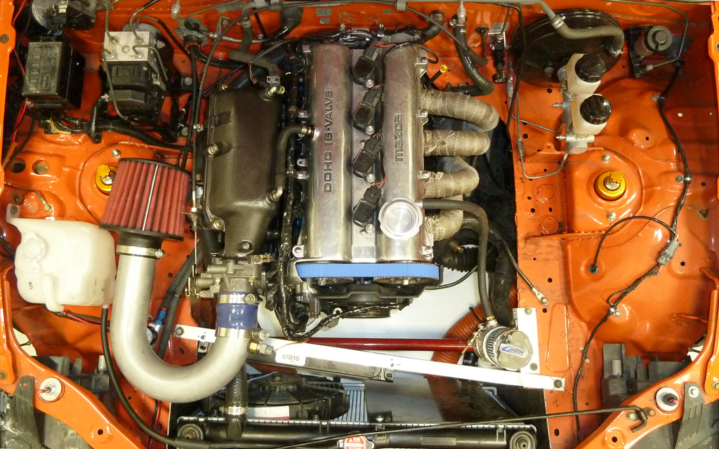
I think it's what Mobius said. I read somewhere in Emilio's blogs that there was excess cooling capacity -- can't find it at the moment though. Excess cooling capacity represent an opportunity to reduce aerodynamic drag (look at the small air inlets on Crusher's air dam for instance). I don't know whether this plate was meant for that or not. Another function the plate might have is to get more air directed to the oil cooler (i.e., without the plate, more air would go through the side not blocked by the fan and oil cooler).
Also note that there is an OEM radiator, probably the thicker automatic version. I've used the OEM radiator on the Silver car for a long time and it's actually pretty good -- never have cooling issues but it's also not blocked by an intercooler.
I think the picture was taken when they dynoed the 2L OGK engine (got 184RWHP). I'm not sure the picture exactly represents the finished car. You'll note that the oil cooler bracket looks like a recent addition (pencil marks at the bolt holes).
Reply
0
0

Elite Member
Joined: Oct 2013
Posts: 2,764
Total Cats: 951
From: Cedar City, UT
Looks amazing man. Good work. It was 108� today and after several hard pulls I was around 213� on the coolant gauge. Not too happy about that. Need to see what I can change. Probably that damn coolant line I haven't rerouted which goes under the headers.
Reply
0
0
 Oil entry/exit at the block also sit higher than the cooler mount points. I read the same, though I ran the oil cooler on my Miata v1 with both lines on the bottom for at least 3,000 miles without issue. I did crank my engine w/o spark & fuel until oil pressure came up (quick) after the initial install.
Last edited by m2cupcar; Jul 24, 2014 at 02:09 PM.
Reply
0
0
Thread Starter
Elite Member
iTrader: (4)
Joined: Mar 2008
Posts: 6,301
Total Cats: 697
From: Granbury, TX
Picked up the engine from the machine shop on Friday afternoon. Basic specs:
-Original to car '95 block/crank/rods
-'99 head with BP05 intake cam (they replaced 3 exhaust valves and did a 3-angle)
-'01 pistons with tri-coat (should be about 10.5:1)
-Added ARP head studs and rod bolts
-Blueprint/dynamic balance
Basic rebuild with just a little extra. KISS.
Spent yesterday doing final assembly of the engine in my 105�F garage. All I have left is mating the transmission and dropping it in. Left on an international trip this morning, so look for a futher update next weekend.
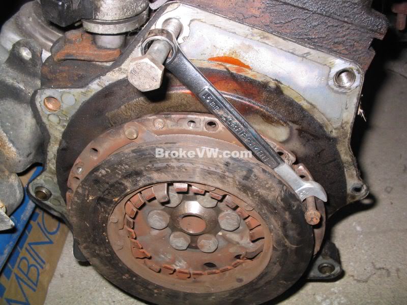
Built a cool tool for myself. Having 2 Miatas and being a track addict, I seem to be assembling more engines than I used to. One part of assembly that was always a bit of a pain was torqueing the flywheel and crankshalf pulley bolts. Mazda has a SST (Special Service Tool) that locks the flywheel for this purpose. So, made my own out of some 1.25" angle iron. Pictures speak for themselves. I did the rivets and then went ahead and hit it with a welder. I don't know if rivets alone would have been sturdy enough.
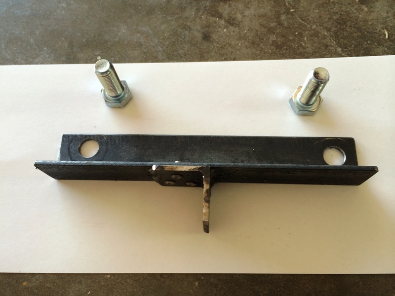
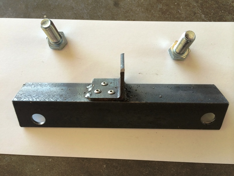
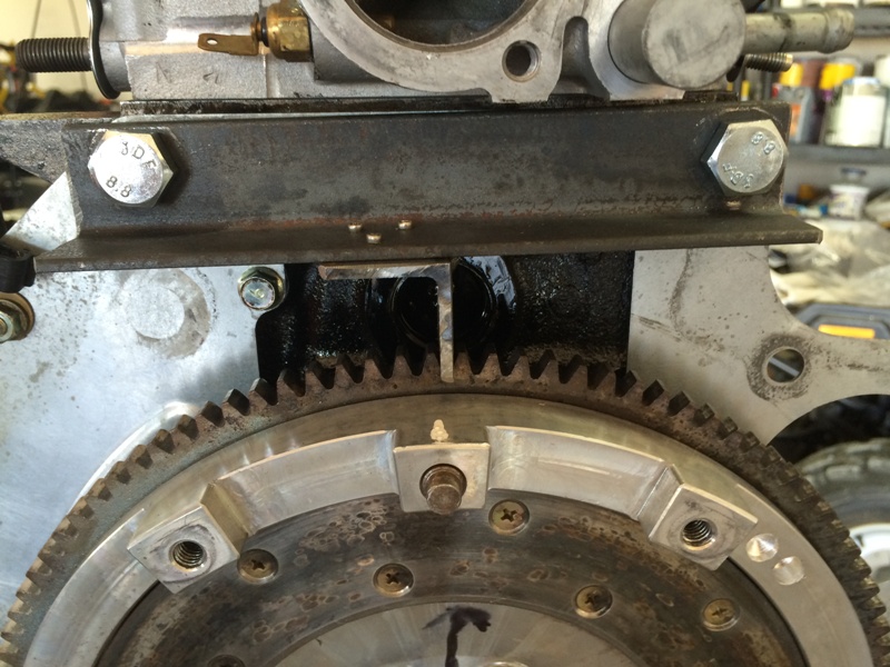
Works great!
-Original to car '95 block/crank/rods
-'99 head with BP05 intake cam (they replaced 3 exhaust valves and did a 3-angle)
-'01 pistons with tri-coat (should be about 10.5:1)
-Added ARP head studs and rod bolts
-Blueprint/dynamic balance
Basic rebuild with just a little extra. KISS.
Spent yesterday doing final assembly of the engine in my 105�F garage. All I have left is mating the transmission and dropping it in. Left on an international trip this morning, so look for a futher update next weekend.
Built a cool tool for myself. Having 2 Miatas and being a track addict, I seem to be assembling more engines than I used to. One part of assembly that was always a bit of a pain was torqueing the flywheel and crankshalf pulley bolts. Mazda has a SST (Special Service Tool) that locks the flywheel for this purpose. So, made my own out of some 1.25" angle iron. Pictures speak for themselves. I did the rivets and then went ahead and hit it with a welder. I don't know if rivets alone would have been sturdy enough.
Works great!
Reply
3
3


Thread Starter
Elite Member
iTrader: (4)
Joined: Mar 2008
Posts: 6,301
Total Cats: 697
From: Granbury, TX
Rebuilt engine installed. Filling with fluids prior to first start. The excitement and anticipation is palpable. Getting under the car to fill the tranny, noticed a steady drip of water from the back of the engine. Crap! Reroute is leaking!
Pulled the BEGI adapter and Kia waterneck from the back of the head and this is what I found:
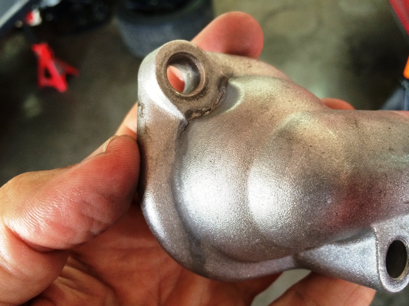
The crack is all the way through. And it's warped, big time. You can see that it's been seeping for a while. I can't believe I didn't notice this when I was putting the parts on with the engine on a stand. Now I get to finally experience the installation with the engine in the car.
I bought this waterneck used. I suspect it had been overtorqued. Note than the BEGI spacer sets up this kind of damage because it doesn't fully support the waterneck at the bolt holes.
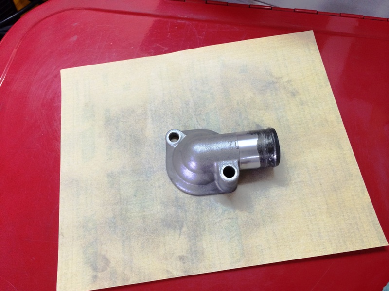
I had another waterneck on hand. This is one that I bought new and used on the Silver car for several thousand miles. It had always been installed with a torque wrench. Inspecting it, noticed that it wasn't cracked, but it also wasn't flat. Even using a torque wrench, the BEGI spacer design results in a warped water neck. The gasket surface was easily fixed with 220 grit:
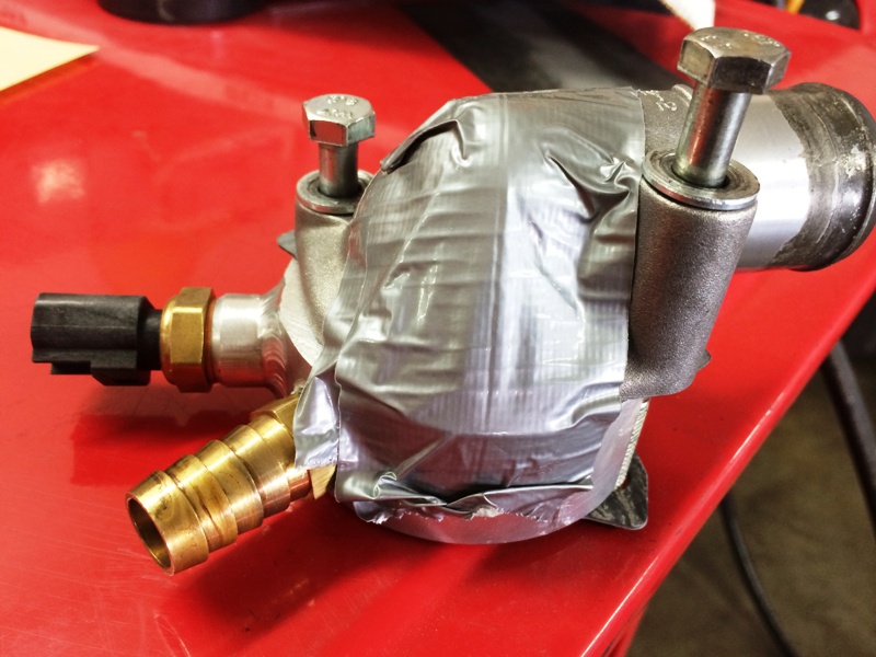
Now to install. I've never installed these parts with the engine in the car, and I've read all the horror stories. As it turned out, it wasn't that bad. Duct tape held the parts together just fine. I loosened the PPF and tilted the engine/transmission forward. That gave me just enough clearance. Thank God for shorty wrenches!
Bottom line, about a 2 hour delay. Still got the initial break-in done tonight. No leaks. So far so good.
My recommendation for service and reinstallation of the BEGI spacer and Kia waterneck:
1. Expect the waterneck to be warped with installation and service. Inspect carefully. If not cracked, use a flat surface and 220 grit to prepare the waterneck for reinstallation.
2. Use genuine Mazda thermostat gaskets.
3. If reinstalling with the engine in the car, use duct tape to keep the assembly together during installation. Tilt the engine/transmission forward for working room.
4. Torque carefully and alternate between the bolts. Remember that the Kia waterneck is weak and the BEGI spacer does not fully support its bolt holes.
I'm drunk posting BTW. Driving Miatas again. Will be back on track this coming weekend. Yay!
Also did a brake service. XP10s up front. XP8s on the back. Freshly turned rotors. Found a stuck caliper on the rear, so got that taken care of too. Brake pedal is high and hard. Feel is amazing. Way better than the Hawk HP+ pads that were on before.
Now to continue the break in!
Pulled the BEGI adapter and Kia waterneck from the back of the head and this is what I found:
The crack is all the way through. And it's warped, big time. You can see that it's been seeping for a while. I can't believe I didn't notice this when I was putting the parts on with the engine on a stand. Now I get to finally experience the installation with the engine in the car.
I bought this waterneck used. I suspect it had been overtorqued. Note than the BEGI spacer sets up this kind of damage because it doesn't fully support the waterneck at the bolt holes.
I had another waterneck on hand. This is one that I bought new and used on the Silver car for several thousand miles. It had always been installed with a torque wrench. Inspecting it, noticed that it wasn't cracked, but it also wasn't flat. Even using a torque wrench, the BEGI spacer design results in a warped water neck. The gasket surface was easily fixed with 220 grit:
Now to install. I've never installed these parts with the engine in the car, and I've read all the horror stories. As it turned out, it wasn't that bad. Duct tape held the parts together just fine. I loosened the PPF and tilted the engine/transmission forward. That gave me just enough clearance. Thank God for shorty wrenches!
Bottom line, about a 2 hour delay. Still got the initial break-in done tonight. No leaks. So far so good.
My recommendation for service and reinstallation of the BEGI spacer and Kia waterneck:
1. Expect the waterneck to be warped with installation and service. Inspect carefully. If not cracked, use a flat surface and 220 grit to prepare the waterneck for reinstallation.
2. Use genuine Mazda thermostat gaskets.
3. If reinstalling with the engine in the car, use duct tape to keep the assembly together during installation. Tilt the engine/transmission forward for working room.
4. Torque carefully and alternate between the bolts. Remember that the Kia waterneck is weak and the BEGI spacer does not fully support its bolt holes.
I'm drunk posting BTW. Driving Miatas again. Will be back on track this coming weekend. Yay!
Also did a brake service. XP10s up front. XP8s on the back. Freshly turned rotors. Found a stuck caliper on the rear, so got that taken care of too. Brake pedal is high and hard. Feel is amazing. Way better than the Hawk HP+ pads that were on before.
Now to continue the break in!
Reply
2
2


