
Ian's 99 build thread

Thread Starter
Elite Member

Joined: Mar 2007
Posts: 5,306
Total Cats: 888
From: Santa Clara, CA
Maybe this weekend! Gotta get the roller jacks working, and my compressor needs a filter/dryer on it. 
Basically you're looking for a scope trace between the two wires on the sensor while it's hooked up to the ABS computer and the wheel is turning? Do you want it with the TC plugged in as well, or not? (In theory it shouldn't be any different, but...)
--Ian
Basically you're looking for a scope trace between the two wires on the sensor while it's hooked up to the ABS computer and the wheel is turning? Do you want it with the TC plugged in as well, or not? (In theory it shouldn't be any different, but...)
--Ian
Reply
 0
0

0

Joined: Apr 2014
Posts: 18,643
Total Cats: 1,870
From: Beaverton, USA
With the TC, I'm going to be pulling off the ABS wire too, and I want to see if the signal changes when traction control is hooked up.
Your TC only looks at the "negative" ABS signal right? Mine looks at both of them, and turns the 0v crossing into a 0v-5v signal. I guess I could try it with just one wire...
Is the racelogic looking at a single abs wire to ground?
Your TC only looks at the "negative" ABS signal right? Mine looks at both of them, and turns the 0v crossing into a 0v-5v signal. I guess I could try it with just one wire...
Is the racelogic looking at a single abs wire to ground?
Reply
0
0

The roller jack is a Bend-Pak RJ45, 4500 pound capacity, air powered hydraulic scissor jack. I bought two, but I have only put one on so far, and I haven't actually used it yet. Didn't have any hydraulic oil left for it on Sunday, and I've been busy with work/etc since then. Ordered a bunch of parts to plumb an air line over to it, so hopefully I'll have them up and running this weekend.
Which lift do you have, is it the same Bend-Pak? If so, is it the runway with the hydraulic ram that's backwards, or the other one? Swapping the ram one would be a PITA, swapping the other one is just a few bolts, an engine hoist, and a few friends.
Which lift do you have, is it the same Bend-Pak? If so, is it the runway with the hydraulic ram that's backwards, or the other one? Swapping the ram one would be a PITA, swapping the other one is just a few bolts, an engine hoist, and a few friends.
Looking at the atlas page for bridge jacks, I just need a sliding jack rather than a rolling one. Looking forward to your review on the usefulness of your bridge jack

Reply
0
0
Thread Starter
Elite Member
Joined: Mar 2007
Posts: 5,306
Total Cats: 888
From: Santa Clara, CA
Do you just call and setup dyno time with Synergy or schedule directly with Lawrence?
It's a chinese knockoff 4-post and looking at the pics for how the RJ45 mounts, it won't work for me. The runways just have a flat lip that sticks out about 3 inches off the bottom of one side. The non ram side has the lip facing out while the ram side has the lip facing in.
Looking at the atlas page for bridge jacks, I just need a sliding jack rather than a rolling one. Looking forward to your review on the usefulness of your bridge jack
You've got a welder, you could always convert it to a Bend-Pak style roller jack.
The roller jacks don't fit under the Miata terribly well, with the tires sitting on 2x6s the jacks will roll under the car, but only barely, and not enough clearance to get the lifting pads on the jack points. OTOH, the crosspiece on the roller jack is exactly in line with the FM frame rails, I could probably just lift it on those.
--Ian
Reply
0
0
Thread Starter
Elite Member
Joined: Mar 2007
Posts: 5,306
Total Cats: 888
From: Santa Clara, CA
With the TC, I'm going to be pulling off the ABS wire too, and I want to see if the signal changes when traction control is hooked up.
Your TC only looks at the "negative" ABS signal right? Mine looks at both of them, and turns the 0v crossing into a 0v-5v signal. I guess I could try it with just one wire...
Is the racelogic looking at a single abs wire to ground?
Your TC only looks at the "negative" ABS signal right? Mine looks at both of them, and turns the 0v crossing into a 0v-5v signal. I guess I could try it with just one wire...
Is the racelogic looking at a single abs wire to ground?
--Ian
Reply
0
0
Joined: Apr 2014
Posts: 18,643
Total Cats: 1,870
From: Beaverton, USA
Reply
0
0
Thread Starter
Elite Member
Joined: Mar 2007
Posts: 5,306
Total Cats: 888
From: Santa Clara, CA
Reply
0
0
Thread Starter
Elite Member
Joined: Mar 2007
Posts: 5,306
Total Cats: 888
From: Santa Clara, CA
Chris and I went to TechShop yesterday and laser cut a faceplate for the display (well, really Chris did it all, I just watched the pretty lights):
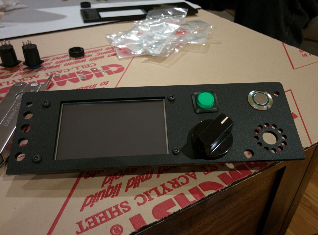
Looking good, unfortunately it turns out the display is upside down, so it needs another pass.
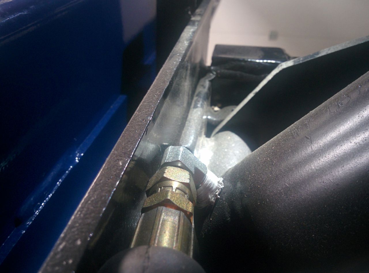
Hooked up the air lines for the roller jacks on the lift and discovered that they'll only go halfway up to the second safety catch position before the hydraulic fittings start to rub against the side plate. WTF. I don't get it, it's almost like these are the wrong roller jacks for my lift, but the part numbers all check out. Need to call Bend-Pak on Monday.
--Ian
Looking good, unfortunately it turns out the display is upside down, so it needs another pass.
Hooked up the air lines for the roller jacks on the lift and discovered that they'll only go halfway up to the second safety catch position before the hydraulic fittings start to rub against the side plate. WTF. I don't get it, it's almost like these are the wrong roller jacks for my lift, but the part numbers all check out. Need to call Bend-Pak on Monday.
--Ian
Reply
0
0
Thread Starter
Elite Member
Joined: Mar 2007
Posts: 5,306
Total Cats: 888
From: Santa Clara, CA
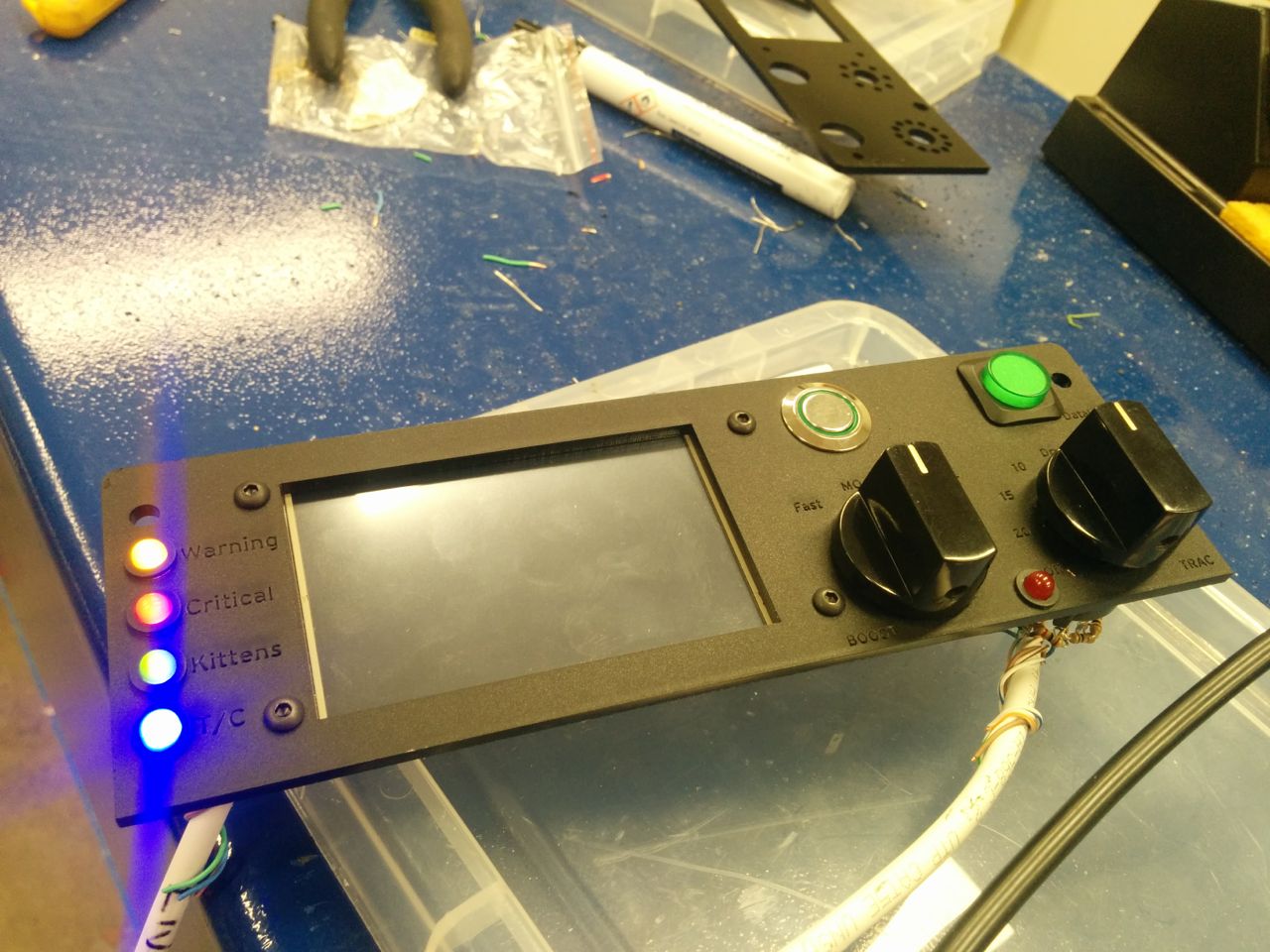
The first stab at the faceplate was upside down, so Chris flipped it in the model and went back to techshop and cut another. Man laser cutters are cool.
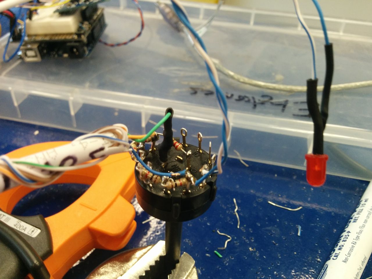
We wired up the 6-position rotary dial switch that's going to take over the control of the RaceLogic TC box. It's basically just a 1K resistor between each of the 6 positions, with a 100 ohm resistor on the sense line, power on one side, ground on the other. We used the second set of poles to turn on the "off" warning LED. This is what the standard RL control box does, we just wanted it mounted in the faceplate rather than being a standalone box. The soldering is ugly because I did it.
The new faceplate has engraved labels on it. Alas, with the matte finish on the acrylic, the engraved labels are pretty hard to read, so they probably need to be filled with paint or ink or something.
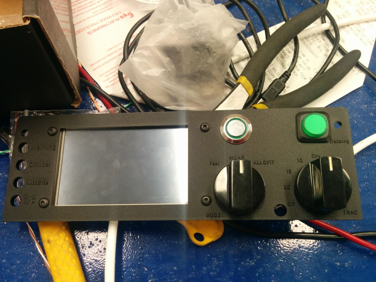
Still need to wire the boost ****. It's a three position **** -- leftmost cuts power to the solenoid for just mechanical boost, rightmost is going to flip the tableswitch input to the MS3. So roughly 10 psi left, 15 psi center, 24 psi right.
One of the buttons is to enable the DL1 data logger, with the built-in LED being the logging status. The other button is as-yet unassigned.
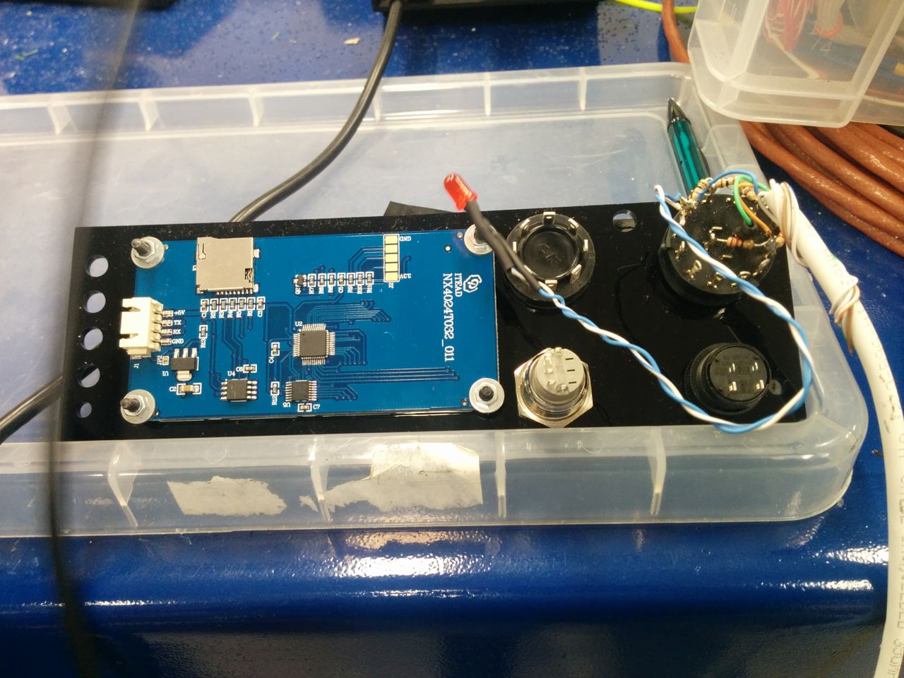
Status LEDs down the left-hand side, yellow and red for warning & critical alerts (Arduino will interpret CAN bus data to drive these). Green is unassigned, blue indicates the RaceLogic TC is active.
--Ian
We wired up the 6-position rotary dial switch that's going to take over the control of the RaceLogic TC box. It's basically just a 1K resistor between each of the 6 positions, with a 100 ohm resistor on the sense line, power on one side, ground on the other. We used the second set of poles to turn on the "off" warning LED. This is what the standard RL control box does, we just wanted it mounted in the faceplate rather than being a standalone box. The soldering is ugly because I did it.
The new faceplate has engraved labels on it. Alas, with the matte finish on the acrylic, the engraved labels are pretty hard to read, so they probably need to be filled with paint or ink or something.
Still need to wire the boost ****. It's a three position **** -- leftmost cuts power to the solenoid for just mechanical boost, rightmost is going to flip the tableswitch input to the MS3. So roughly 10 psi left, 15 psi center, 24 psi right.
One of the buttons is to enable the DL1 data logger, with the built-in LED being the logging status. The other button is as-yet unassigned.
Status LEDs down the left-hand side, yellow and red for warning & critical alerts (Arduino will interpret CAN bus data to drive these). Green is unassigned, blue indicates the RaceLogic TC is active.
--Ian
Reply
6
6


Wowzers, that's all kinds of win. I love stuff like this.
Look up 'roll mark painting.' Its a thing from the firearms world so there will be a lot of gun content when you do that google search, but I feel like that is exactly what you are looking for. The nice thing is you have an entire second faceplate to practice on!
Reply
0
0
Thread Starter
Elite Member
Joined: Mar 2007
Posts: 5,306
Total Cats: 888
From: Santa Clara, CA
Most of the credit for the labels has to go to Chris.
"fast" == mechanical boost, around 9 psi.
"MOAR" == my normal boost level, 15 psi. This is low enough to hopefully not stress the 6-speed.
"ALLOFIT" == everything I've tuned for, 24 psi currently. Used when there's a Corvette sitting next to me at a traffic light or something.
Roll mark painting looks like the kind of thing we were discussing, yeah. One of the challenges is to find a paint that uses a solvent for wiping up excess that won't also dissolve the acrylic. We engraved words on some of the scrap so as to have bits to practice with.
We talked about other materials for making the faceplate, like anodized aluminum. You can't cut that with a laser cutter (well, you can, but not with the wimpy 60 watt laser they have at TechShop), but you can use the water jet cutter for cutting and then engrave the anodizing off with the laser. It looks cool.
Speaking of boost level tuning, anyone know what the MS3 expects for inputs on tableswitch? Do I want to ground it to switch it or apply +5?
--Ian
Reply
0
0
I *believe* its path to ground, but you know better than to trust my word on electrical stuff 
Try plain old Testors model paint and a wet paper towel to clean up excess. Fill and wipe until it looks the way you want it. That's how I did it on my AR15 and its held up for years against firearms cleaning solvents and lube. The only thing you'll be able to read on that black is probably white and yellow, red has a tendency to just straight disappear into the black. Bright pink on the other hand...
Try plain old Testors model paint and a wet paper towel to clean up excess. Fill and wipe until it looks the way you want it. That's how I did it on my AR15 and its held up for years against firearms cleaning solvents and lube. The only thing you'll be able to read on that black is probably white and yellow, red has a tendency to just straight disappear into the black. Bright pink on the other hand...
Reply
0
0
Joined: Apr 2014
Posts: 18,643
Total Cats: 1,870
From: Beaverton, USA
Any chance on that scope trace?
I just want to see what the signal across the wheel sensors is when its all hooked up and powered by the ABS unit.
I just want to see what the signal across the wheel sensors is when its all hooked up and powered by the ABS unit.
Reply
0
0
Reply
0
0
Thread Starter
Elite Member
Joined: Mar 2007
Posts: 5,306
Total Cats: 888
From: Santa Clara, CA
I don't think it does.
What's been slowing me down on this is the wires are all sealed up except at the input connector to the Racelogic, and now that I've actually built a mount for the MS3, the RL is a PITA to get to. So it's not just "jack it up and scope the wires", I need to spend an hour taking stuff apart and putting it back together again. (either that or cut the wires and then resplice them, which I'd prefer not to do).
--Ian
Reply
0
0


