
Just Another F20C build... <Preview>


That's what I'm leaning towards. If circa 5000rpm turns out to be above the optimal engagement point, it'll just result in a bit of a vtec-kicked-in-yo feel at 5krpm on full throttle. No big deal, and certainly less of a dramatic kick than the standard 6200rpm engagement point. I think we're on different pages re. my reasons for wanting load dependent vtec engagement - it's not so that I don't have to change down a gear or two (or three) on the motorway, it's so that when I'm playing on back roads or at the track, and find myself for whatever reason down at 4krpm coming out of a corner at full throttle, vtec will kick in yo at the optimal point instead of a post-optimal motorway-friendly point.
A very costly but better option: add i-VTEC (and AEM EMS, lol)
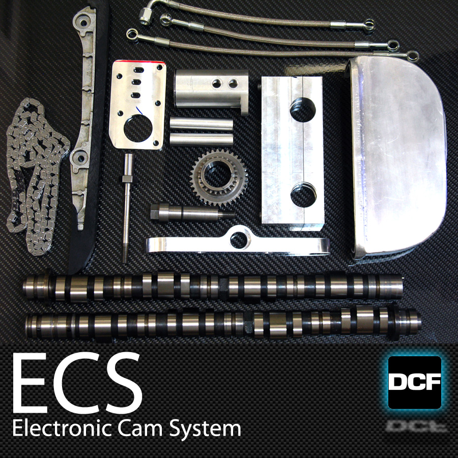
http://designcraftfab.com/online-sto...nic-cam-system
http://image.hondatuningmagazine.com...ed_version.jpg
C-West's turbo S2000 @ 4k rpm, turbo/psi???
http://image.hondatuningmagazine.com...dynographs.jpg
Reply
 0
0

0

Thread Starter
Junior Member
Joined: Dec 2010
Posts: 375
Total Cats: 20
From: UK, in Cambridgeshire or wherever work takes me.
I saw a report of the first F20 with iVTEC. It looked like it was a real fiddly bastard to do. And an expensive bastard, too. That kit, even plus AEM, looks good value in comparison! Still massive ���� though for the benefits.... maybe it's an option a few years down the line, huh 
Reply
0
0
Thread Starter
Junior Member
Joined: Dec 2010
Posts: 375
Total Cats: 20
From: UK, in Cambridgeshire or wherever work takes me.
Damn I miss this thing.
Cage kit arrived today. It's being welded in this coming week. With any luck the end of the major fabrication stage is in sight. Think I said that a month ago though... ah well.
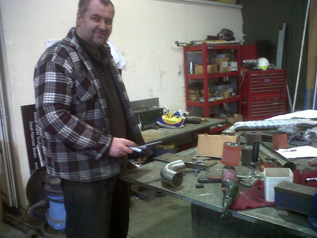
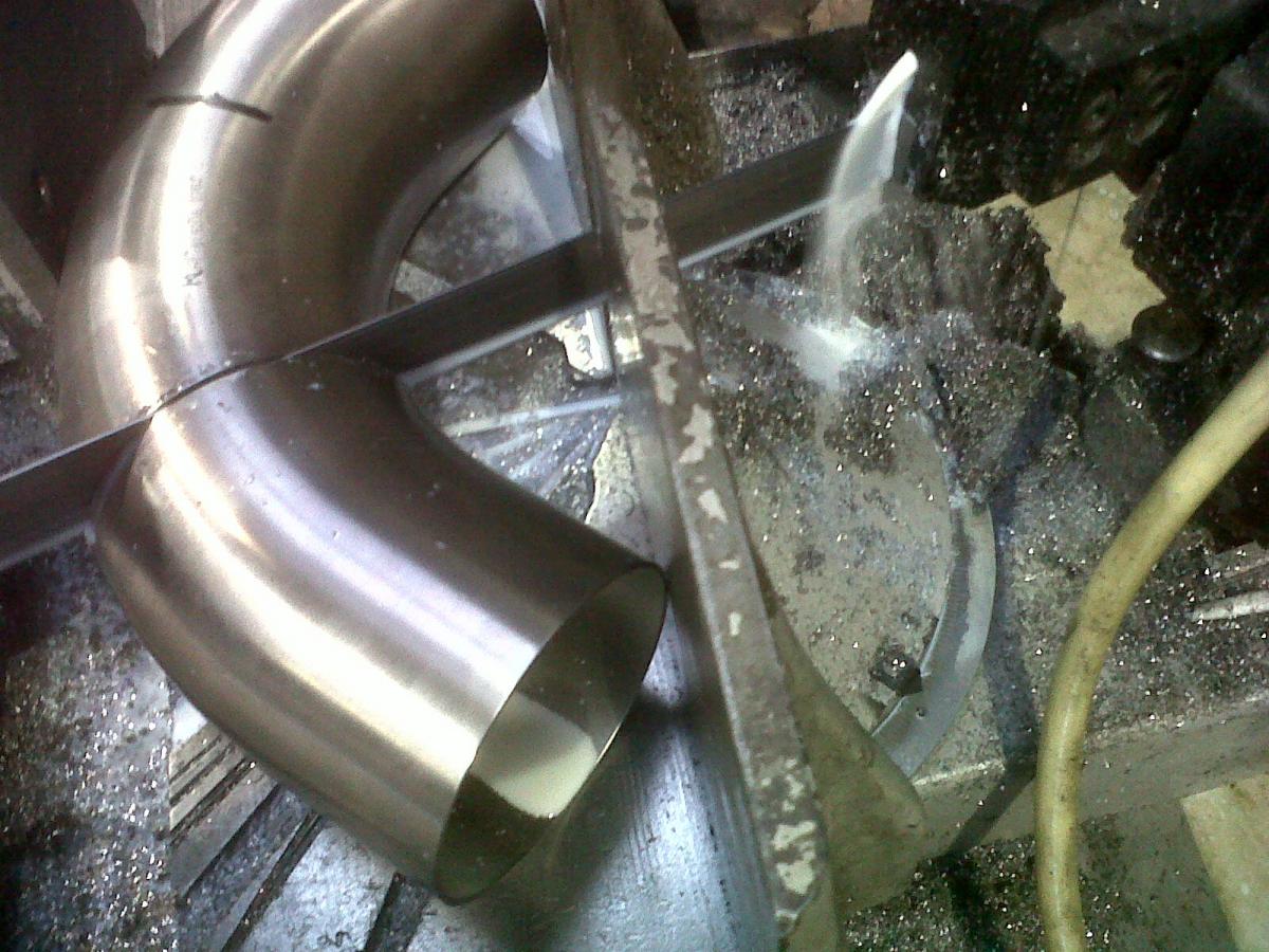
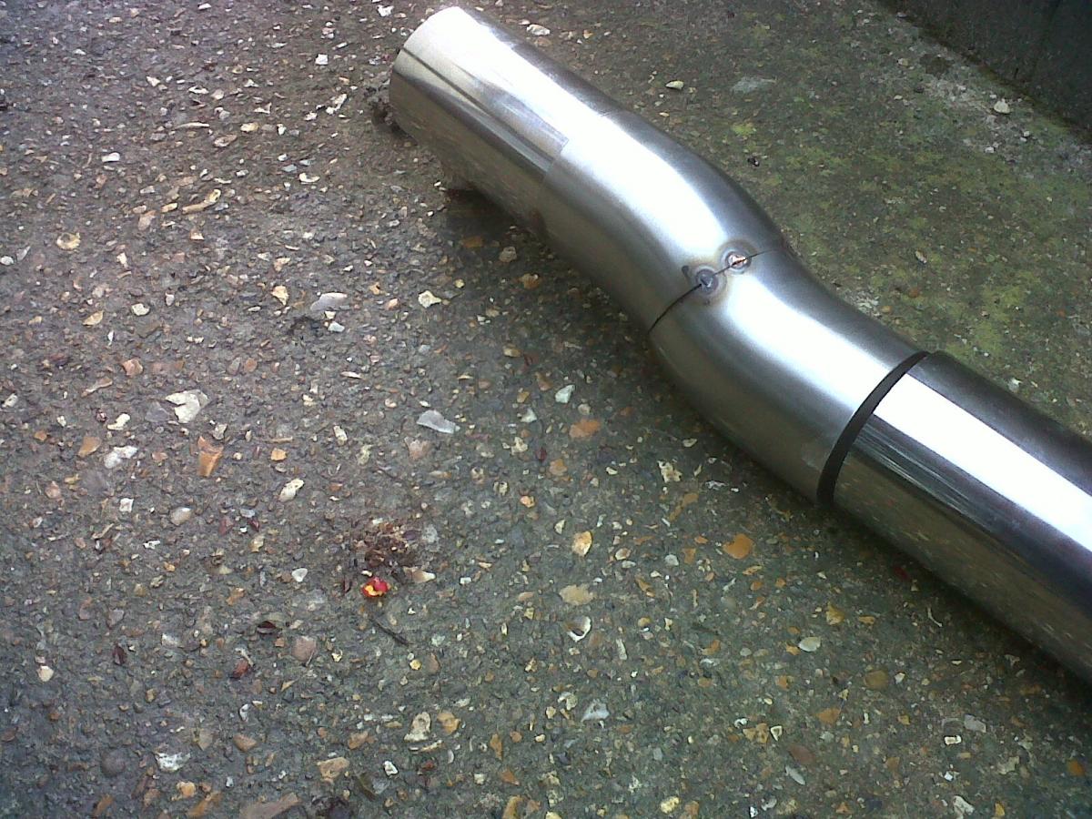
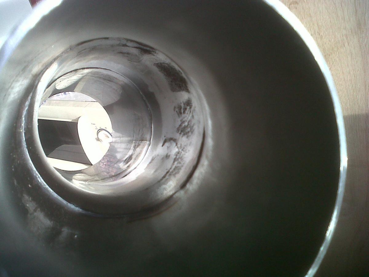
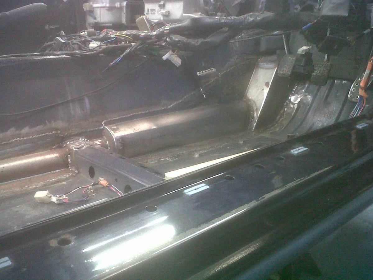
I started making the main section of the exhaust this afternoon with a guy called Danius from work. He now has the dubious honour of being immortalised on mt.net in the photo below He's been fabricating things out of stainless for longer than I've been alive - although the vast majority of stuff he does uses 3mm wall thickness (ie twice the thickness of this exhaust wall tubing) and also originates from architects' drawings, whereas with this bit of fabbing we have to replicate exactly an initial exhaust that was made up by the shop. Getting the rotations, angles and lengths right of a twisting bit of tube is a tad tricky without drawings, dimensions or access to the car. Photos of the result of our effort will be up tomorrow...
Cage kit arrived today. It's being welded in this coming week. With any luck the end of the major fabrication stage is in sight. Think I said that a month ago though... ah well.
I started making the main section of the exhaust this afternoon with a guy called Danius from work. He now has the dubious honour of being immortalised on mt.net in the photo below
He's been fabricating things out of stainless for longer than I've been alive - although the vast majority of stuff he does uses 3mm wall thickness (ie twice the thickness of this exhaust wall tubing) and also originates from architects' drawings, whereas with this bit of fabbing we have to replicate exactly an initial exhaust that was made up by the shop. Getting the rotations, angles and lengths right of a twisting bit of tube is a tad tricky without drawings, dimensions or access to the car. Photos of the result of our effort will be up tomorrow...
Reply
0
0
Thread Starter
Junior Member
Joined: Dec 2010
Posts: 375
Total Cats: 20
From: UK, in Cambridgeshire or wherever work takes me.
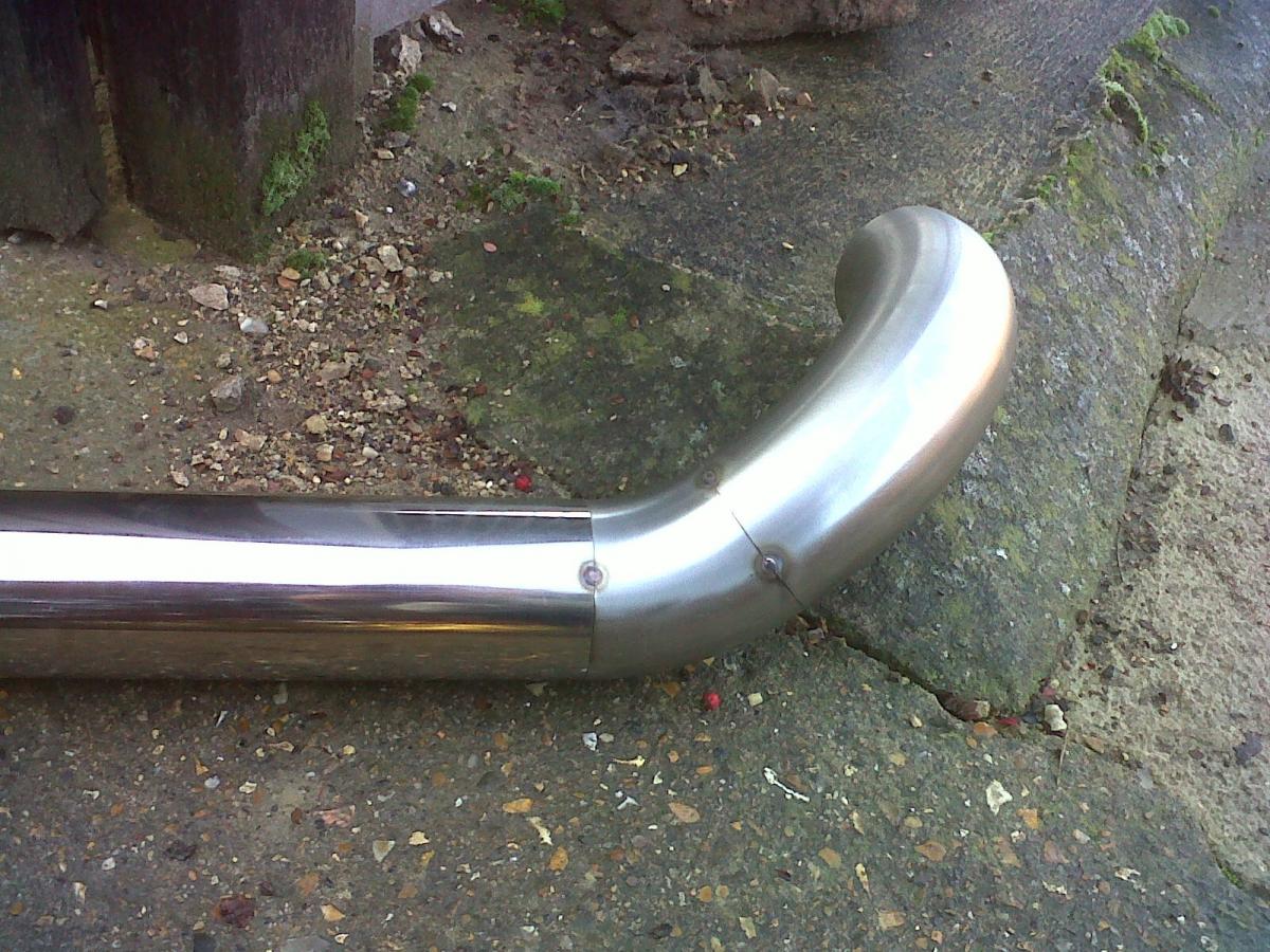
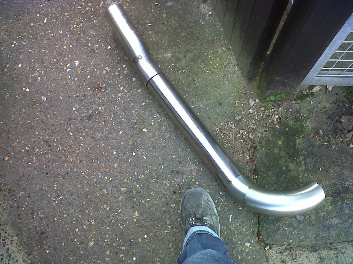
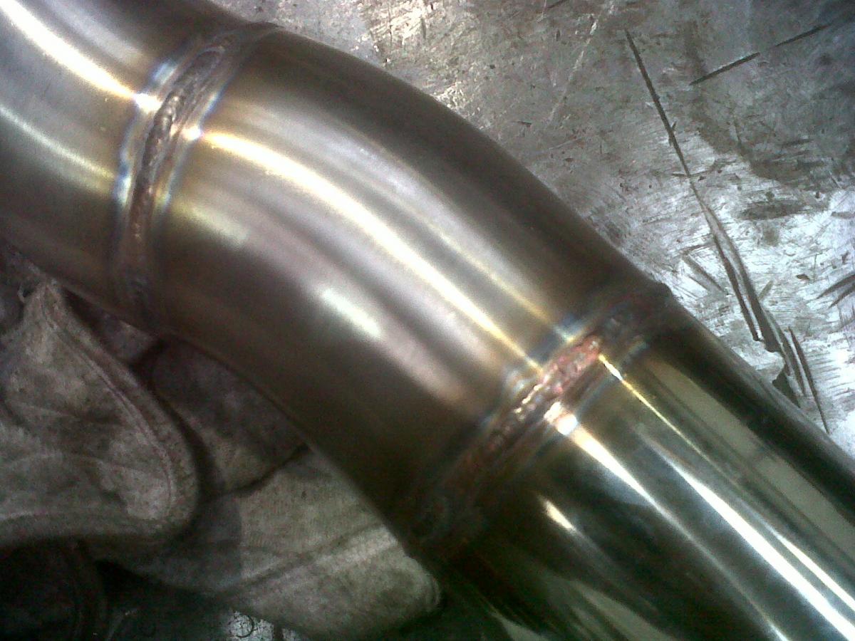
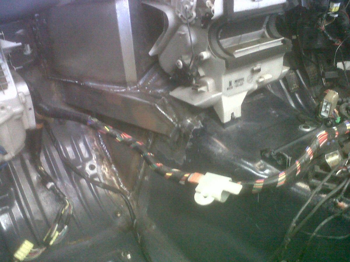
Got the exhaust all cut and tacked in two main sections this afternoon. Then went and checked it on the car. It fits fine, aside from a 3-4mm gap at the top between the two sections. So I'll grind that down slightly, then break the tacks and finish the end of each tube, then smooth out the joints internally as best I can, then get Danius to weld it, then I might polish the whole lot depending on how much time I have after work at the start of next week. Most of it will be hidden by the flat underbody so it really shouldn't matter to me what it looks like, but I just like things being right!
Reply
1
1

Thread Starter
Junior Member
Joined: Dec 2010
Posts: 375
Total Cats: 20
From: UK, in Cambridgeshire or wherever work takes me.
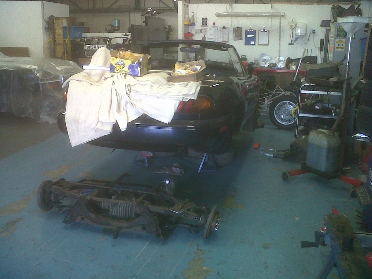
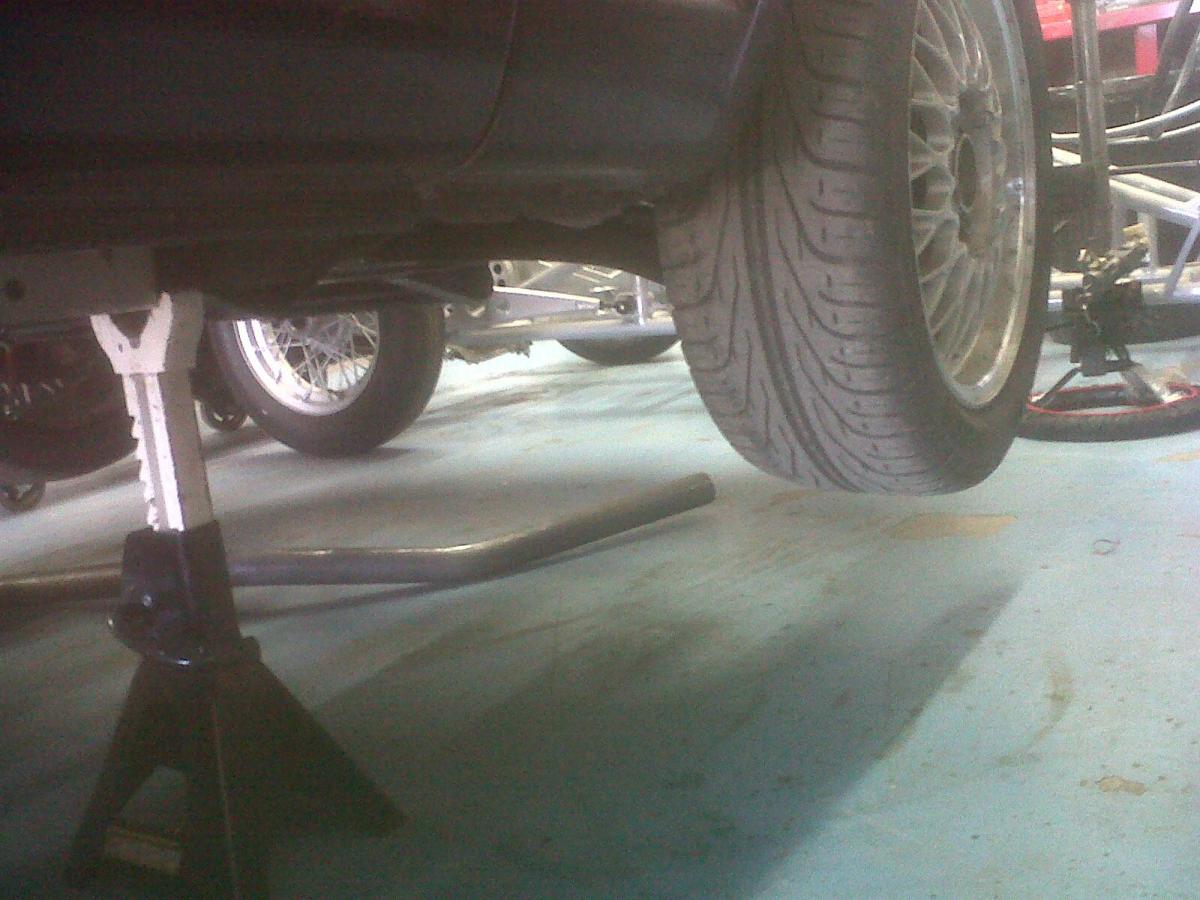
Yeah it does look very low, huh. I mean, I wanted it low because of the standard ride height I'll be running, but in that photo it does look lower than I'd have expected. Won't know how low the sump will be 'til it's sitting on the new springs and dampers.
Reply
0
0
Thread Starter
Junior Member
Joined: Dec 2010
Posts: 375
Total Cats: 20
From: UK, in Cambridgeshire or wherever work takes me.
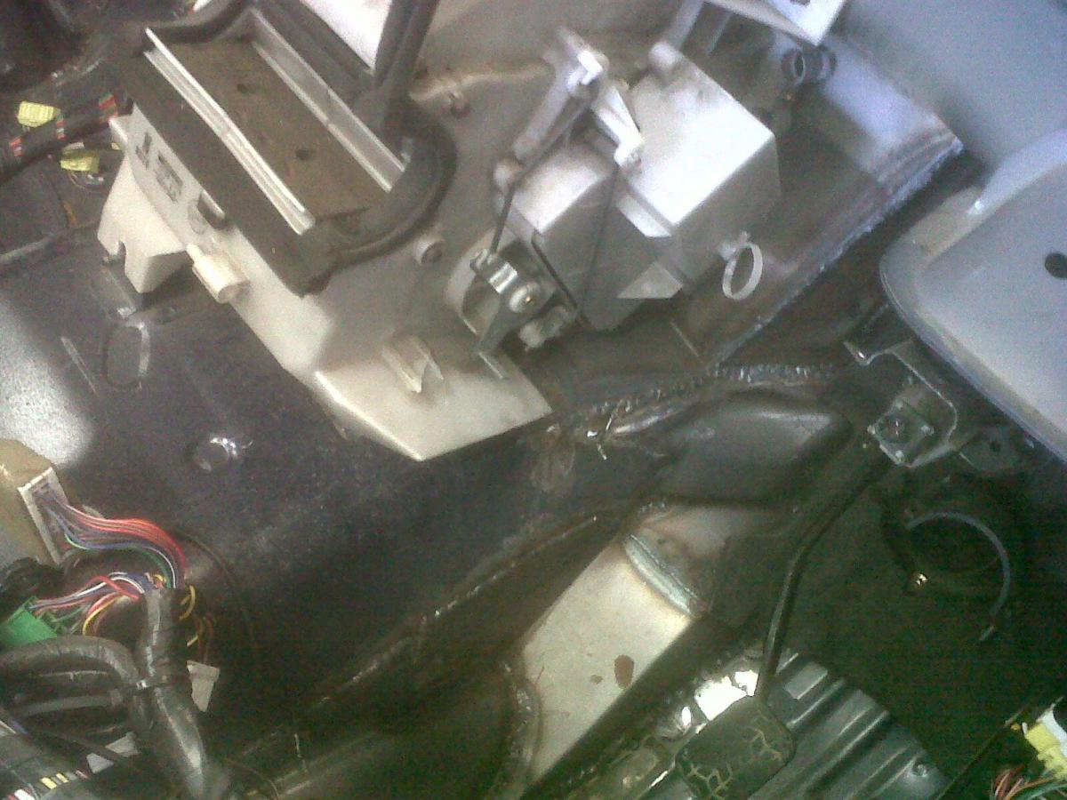
Is there anyone out there who would be willing to measure the height of the sump/subframe/whatever the lowest point in the engine bay is on a BP-engined Miata in relation to the frame rails? As I've said, my sump and subframe now sit below the frame rail height (see photo in post 151 halfway down page 6 of this thread). I'm very very interested to know the 'standard' height. I suppose you could measure it with a long straight edge held against the frame rail. Or, less ideally, by taking a dip measurement from the frame rail to the ground, then taking another dip measurement from the sump to the ground and comparing the two. PLEEEEEEEEASE
Reply
0
0
Thread Starter
Junior Member
Joined: Dec 2010
Posts: 375
Total Cats: 20
From: UK, in Cambridgeshire or wherever work takes me.
Frustration number 1: The shop hasn't touched my car in two weeks.
Frustration number 2: Realised halfway through polishing the welds down on the exhaust that polishing an exhaust is a terrible idea, because I'm creating thin spots in a piece of metal that gets very hot...
FN3: The high temp silicone (er... BBQ paint?) that I bought to spray this middle section of the exhaust comes in a can that bungs up literally every five seconds. Now it's completely bunged, and no amount of poking with wire can save it. So I have an exhaust that's half polished and half painted.
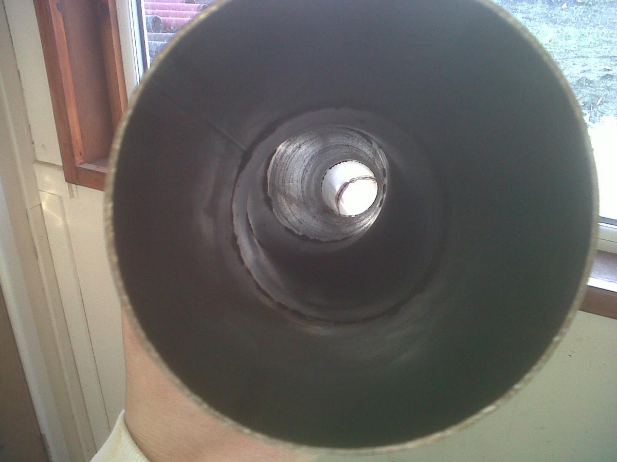
Although, internally, the exhaust is pretty good. The shop originally MIG'd the exhaust up, which left large weld blobs all around the inside of the tube at every joint. This new exhaust, that I had Danius make, was TIG'd by Danius then Dynafile-d by me, which has resulted in it being considerably smoother inside. Which should gain me at least the power of a whole horse. Every little helps though.
Frustration number 2: Realised halfway through polishing the welds down on the exhaust that polishing an exhaust is a terrible idea, because I'm creating thin spots in a piece of metal that gets very hot...
FN3: The high temp silicone (er... BBQ paint?) that I bought to spray this middle section of the exhaust comes in a can that bungs up literally every five seconds. Now it's completely bunged, and no amount of poking with wire can save it. So I have an exhaust that's half polished and half painted.
Although, internally, the exhaust is pretty good. The shop originally MIG'd the exhaust up, which left large weld blobs all around the inside of the tube at every joint. This new exhaust, that I had Danius make, was TIG'd by Danius then Dynafile-d by me, which has resulted in it being considerably smoother inside. Which should gain me at least the power of a whole horse. Every little helps though.
Reply
0
0


Thread Starter
Junior Member
Joined: Dec 2010
Posts: 375
Total Cats: 20
From: UK, in Cambridgeshire or wherever work takes me.
MIG = bad
TIG = good
TIG FTW
It's slightly depressing still being at the welding stage. I just want things to look shiny and painted and braided-hosed IMMEDIATELY RIGHT NOW.
All I can say at this stage, is that I have the utmost respect for all you other guys who, like me, put a very significant percentage of your life savings into building a car. My God it takes patience and perseverance. I'm not even really building this car, but I've still spent literally hours every day for the last five months thinking about it/researching it/annoying the people building it with stupid ideas and rambling musings.
As an aside, if you want to see the most impressive build thread I've ever seen, look here: http://pistonheads.com/gassing/topic...+Refresh&mid=0
The attention to detail is absolutely outrageous. As is the resolve of the guy building it. It spans three years, and numerous massive set backs. And then two days ago, this was posted:
"No video. Car blew the oil filter off on the dyno, huge fireball, whole thing's fked. The end. Thanks for reading."
It's probably the best tragic novel me and hundreds of others have read And is probably responsible for me hoping like hell at the moment that my build doesn't have a similarly bloody awful ending!
TIG = good
TIG FTW
It's slightly depressing still being at the welding stage. I just want things to look shiny and painted and braided-hosed IMMEDIATELY RIGHT NOW.
All I can say at this stage, is that I have the utmost respect for all you other guys who, like me, put a very significant percentage of your life savings into building a car. My God it takes patience and perseverance. I'm not even really building this car, but I've still spent literally hours every day for the last five months thinking about it/researching it/annoying the people building it with stupid ideas and rambling musings.
As an aside, if you want to see the most impressive build thread I've ever seen, look here: http://pistonheads.com/gassing/topic...+Refresh&mid=0
The attention to detail is absolutely outrageous. As is the resolve of the guy building it. It spans three years, and numerous massive set backs. And then two days ago, this was posted:
"No video. Car blew the oil filter off on the dyno, huge fireball, whole thing's fked. The end. Thanks for reading."
It's probably the best tragic novel me and hundreds of others have read
And is probably responsible for me hoping like hell at the moment that my build doesn't have a similarly bloody awful ending!
Reply
0
0
Thread Starter
Junior Member
Joined: Dec 2010
Posts: 375
Total Cats: 20
From: UK, in Cambridgeshire or wherever work takes me.
Alec, I read that post pre-edit, and I agree that trying to tune the hell out of a notoriously unreliable engine wasn't very sensible. He had people saying 'put a Honda engine in it' from the start. I think he stuck with the Rover because the whole ethos of his build was to optimise every part of the OEM Lotus spec. But yeah, if he'd just put a K20 in it like everyone else these days, he would have saved at least a year of headaches...
PS, cage goes in this week. I really hope it does, anyway. Pics in a few days
PS, cage goes in this week. I really hope it does, anyway. Pics in a few days
Reply
0
0

Thread Starter
Junior Member
Joined: Dec 2010
Posts: 375
Total Cats: 20
From: UK, in Cambridgeshire or wherever work takes me.
Got an update from my dad about progress today. I haven't had the ***** to go and see the car for a while, so my dad went over to the shop when he was out.
Sounds like there's still a fair bit of fabrication to do.
Things that are done include fitting all the polybushes, and patching up the steering system as part of the de-power-assisting process. Turns out I won't be de-servoing my brakes, as here in the UK a car that is fitted with a servo needs to retain that servo to pass its MOT. I just checked a gov website, and it confirmed this to be the case. Hmmph.
The 'box has been taken off in order to install the clutch and lighter flywheel. And a little bit more of the cage is in.
Things I still need to buy now amount to just tyres, dampers, and ECU. I'm putting off buying the tyres for as long as I can, because there's no point having the rubber sitting around for longer than is necessary. The dampers have finally been completed this week. And I've tried to buy a Dastek Unichip from tdi-plc.com three times now, and failed each time. The first two times my email sent the confirmation letter that I needed to respond to straight to my spam box. The third time involved phoning them up and giving them my details over the phone... but my account hasn't been debited and I've heard nothing from them. The product isn't in stock at the moment, which complicates things ever so slightly, but really shouldn't complicate things THIS much. I emailed them again a few days ago and I'm waiting on a reply. I'll phone them again on Monday.
The whole situation is pretty bloody frustrating at the moment. But not completing it is simply not an option. I'll have upwards of �15k in this car by the time it's done, which is absolutely fine with me as long as the car turns out to be the comprehensively considered reliable hassle-free funmobile that I hope it will be.
Reply
0
0
Thread Starter
Junior Member
Joined: Dec 2010
Posts: 375
Total Cats: 20
From: UK, in Cambridgeshire or wherever work takes me.
Right. Going to see the car tomorrow. Will take piktars and report back.
Points:
Cage is done, and is off being powdercoated;
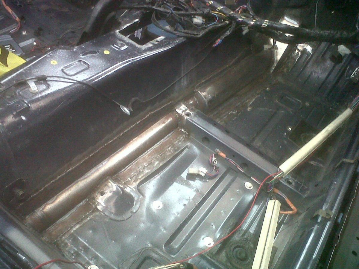
Trans tunnel fabbing is done;
Dastek Unichip Q arrived today. I didn't realise it's mappable not just in full throttle, but part throttle too, over 12 increments. Not bad for a piggyback. I have no idea how to tune it, but I'm going to buy a couple of books and try and get my head around it all. The user interface is in the form of the typical 3D maps for engine load vs rpm etc, that you're all used to.
Here's an interesting article on the Unichip, with general stuff about how this particular piggyback works:
http://sgeauto.com/2010/07/unichip-q...back-computer/
Again, I'm surprised at the depth of tuning it offers. Hopefully the reality will meet my newly heightened expectations, and hopefully I won't have trouble when trying to add fuel, which is a problem users often encounter with other piggybacks on this engine. I don't see why this piggyback would be different, but I'm no expert.
Regarding tuning, I received an interesting response from the MD of Torque Developments International when I hinted at buying some det cans and using their dyno to tune my car. Part of it I've quoted below. Someone feel free to explain it to me - I don't understand his reference to 'the danger zone'. I thought an engine either knocks, however slightly, or it doesn't, but Mark seems to suggest there's a dangerous grey zone between the two states:
"Contrary to popular belief det cans are not (or more accurately should not!) be used for tuning, they’re just used as a precautionary measure along with electronic detection devices. It is possible set the ignition timing into the danger zone before detonation occurs. "
Anyway, that's enough rambling. Pics tomorrow.
Points:
Cage is done, and is off being powdercoated;
Trans tunnel fabbing is done;
Dastek Unichip Q arrived today. I didn't realise it's mappable not just in full throttle, but part throttle too, over 12 increments. Not bad for a piggyback. I have no idea how to tune it, but I'm going to buy a couple of books and try and get my head around it all. The user interface is in the form of the typical 3D maps for engine load vs rpm etc, that you're all used to.
Here's an interesting article on the Unichip, with general stuff about how this particular piggyback works:
http://sgeauto.com/2010/07/unichip-q...back-computer/
Again, I'm surprised at the depth of tuning it offers. Hopefully the reality will meet my newly heightened expectations, and hopefully I won't have trouble when trying to add fuel, which is a problem users often encounter with other piggybacks on this engine. I don't see why this piggyback would be different, but I'm no expert.
Regarding tuning, I received an interesting response from the MD of Torque Developments International when I hinted at buying some det cans and using their dyno to tune my car. Part of it I've quoted below. Someone feel free to explain it to me - I don't understand his reference to 'the danger zone'. I thought an engine either knocks, however slightly, or it doesn't, but Mark seems to suggest there's a dangerous grey zone between the two states:
"Contrary to popular belief det cans are not (or more accurately should not!) be used for tuning, they’re just used as a precautionary measure along with electronic detection devices. It is possible set the ignition timing into the danger zone before detonation occurs. "
Anyway, that's enough rambling. Pics tomorrow.
Reply
0
0
Thread Starter
Junior Member
Joined: Dec 2010
Posts: 375
Total Cats: 20
From: UK, in Cambridgeshire or wherever work takes me.
Calling hingstonwm - I just noticed in your build that your sump guard seems to extend at least a couple of inches below the original position, yet you don't seem to have mentioned any tarmac scraping issues. This makes me feel slightly more optimistic about my car's situation.
If you're reading, can you let me know exactly how much ground clearance you lost with that sump guard, and whether or not it's caused any tarmac-bashing issues. Details on ride height and spring weight would also be useful, in order for me to get the best idea of whether or not I need to start saving for a dry sump system...
If you're reading, can you let me know exactly how much ground clearance you lost with that sump guard, and whether or not it's caused any tarmac-bashing issues. Details on ride height and spring weight would also be useful, in order for me to get the best idea of whether or not I need to start saving for a dry sump system...
Reply
0
0
I used 1.5 inch dim tubing, so I lost 1.5 inches of ground clearance, front is lowered a out 1/2 inch. Running 550# springs on the front. Ride is a little harsh and on rare occasion I bottom on the skid plate
Reply
0
0


