
Just Another F20C build... <Preview>


Thread Starter
Junior Member
Joined: Dec 2010
Posts: 375
Total Cats: 20
From: UK, in Cambridgeshire or wherever work takes me.
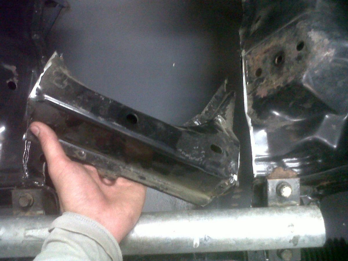
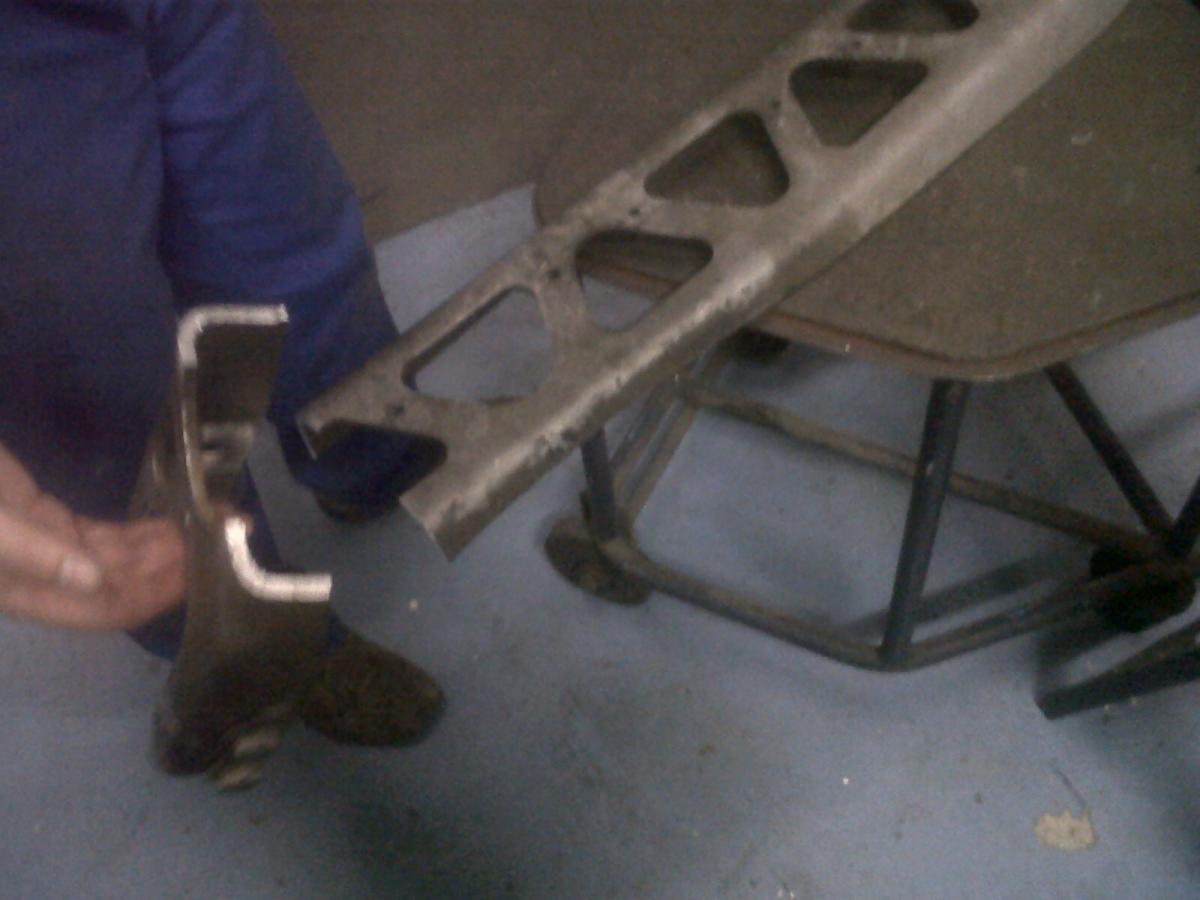
Holy crap it worked. That's a pic of the crossmember section that's been cut out. Here's some more:
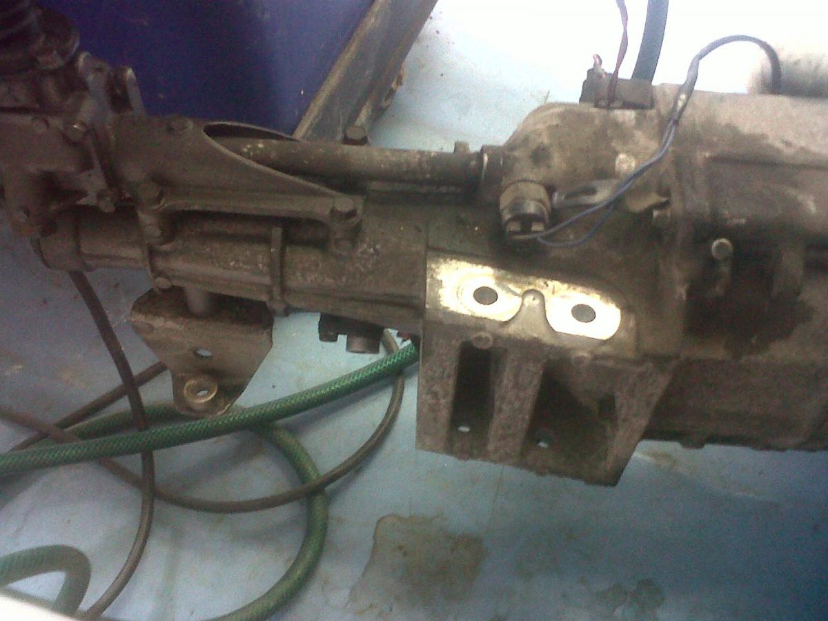
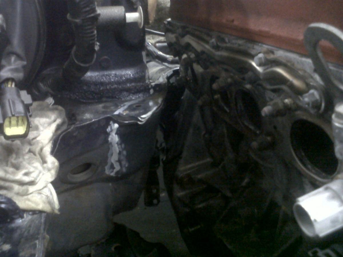
Notice the pretty substantial PPF mount on the Mazda gearbox...
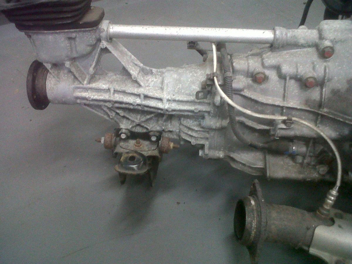
And the lack of mount on the Honda 'box. Quent is going to get his machinist to machine a block of aluminium which will use the two existing mounting points on each side of the gearbox, and will wrap around the top of the transmission. This will be further supported by bracing running to all other available existing mounting points on the box. This is how the PPF is being mounted.
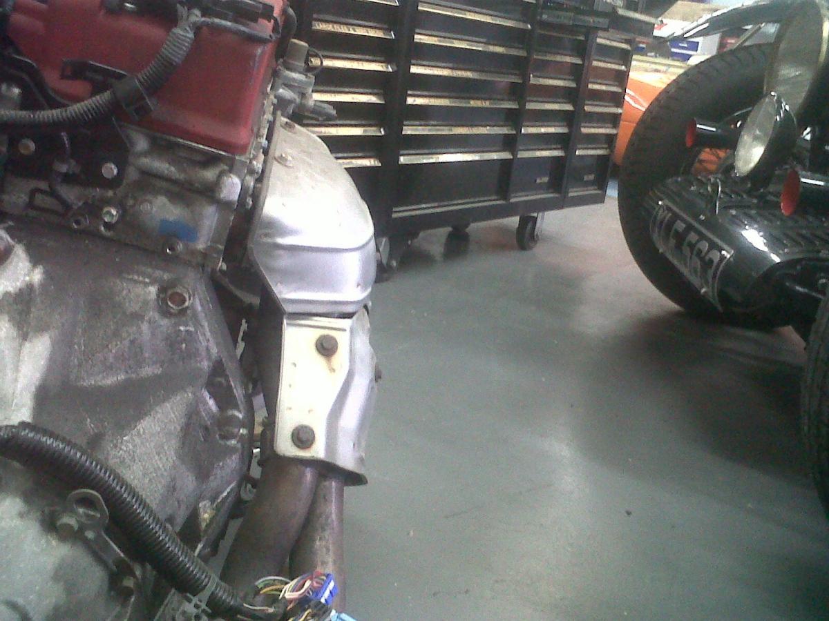
The manifold heat shields take up too much room, so will be removed. I'll wrap the manifold, but probably with a non-baller one piece heat shield, because I'm worried about the mild steel rotting away if I wrap it both tightly and in such a way that I can't easily remove said wrapping. I won't be getting the manifold ceramic coated because I'm not THAT baller. One nil hingstonwm
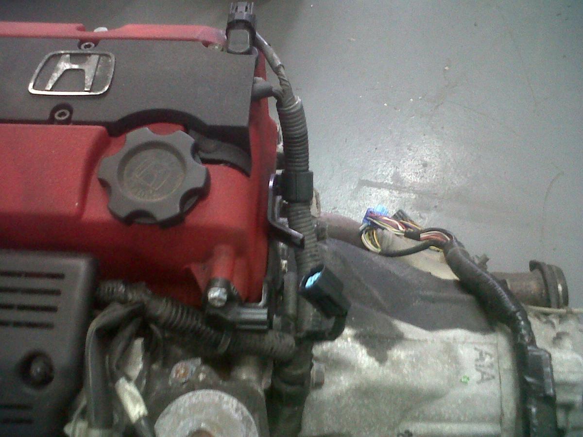
Annoying sticky-outy cam angle sensor is annoying.
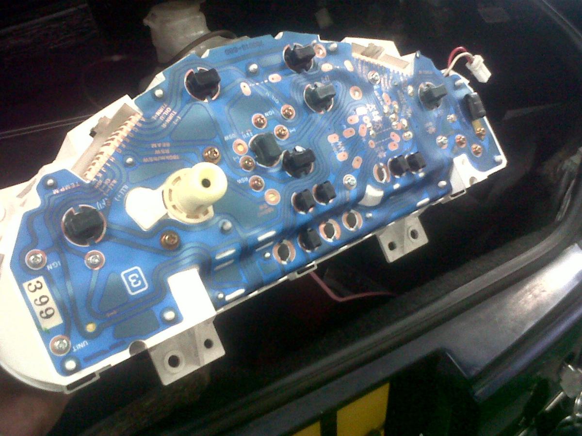
This is what the back of a '95 Eunos dash binnacle looks like. Obviously, it's one big printed circuit board. As I've mentioned, the inability to remove and replace just the tacho means I'll be replacing all gauges with Stack items.
Notice the pretty substantial PPF mount on the Mazda gearbox...
And the lack of mount on the Honda 'box. Quent is going to get his machinist to machine a block of aluminium which will use the two existing mounting points on each side of the gearbox, and will wrap around the top of the transmission. This will be further supported by bracing running to all other available existing mounting points on the box. This is how the PPF is being mounted.
The manifold heat shields take up too much room, so will be removed. I'll wrap the manifold, but probably with a non-baller one piece heat shield, because I'm worried about the mild steel rotting away if I wrap it both tightly and in such a way that I can't easily remove said wrapping. I won't be getting the manifold ceramic coated because I'm not THAT baller. One nil hingstonwm
Annoying sticky-outy cam angle sensor is annoying.
This is what the back of a '95 Eunos dash binnacle looks like. Obviously, it's one big printed circuit board. As I've mentioned, the inability to remove and replace just the tacho means I'll be replacing all gauges with Stack items.
Reply
 0
0

0
Thread Starter
Junior Member
Joined: Dec 2010
Posts: 375
Total Cats: 20
From: UK, in Cambridgeshire or wherever work takes me.
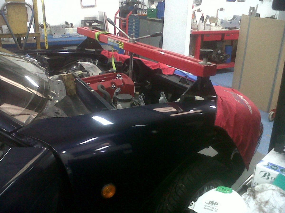
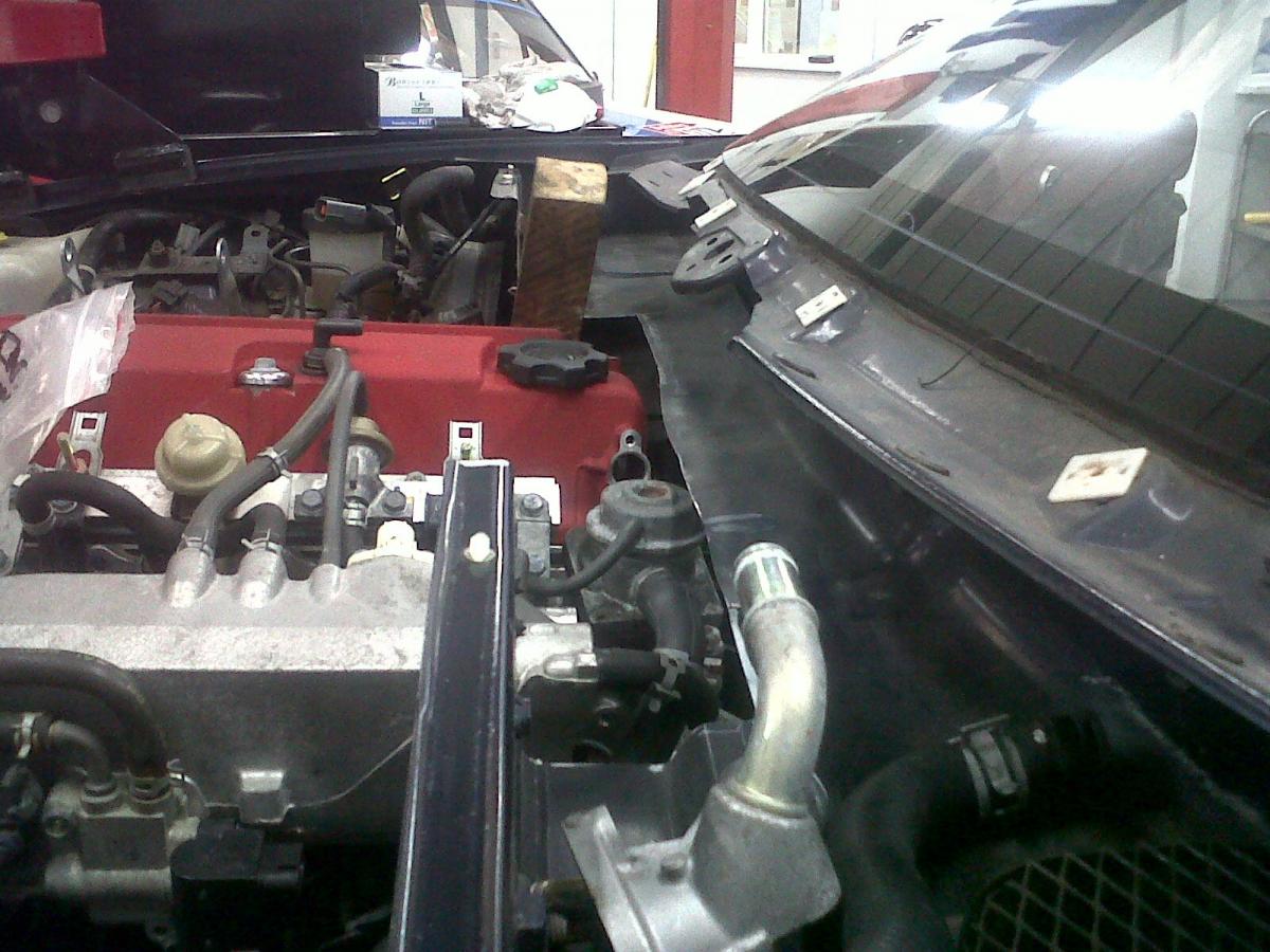
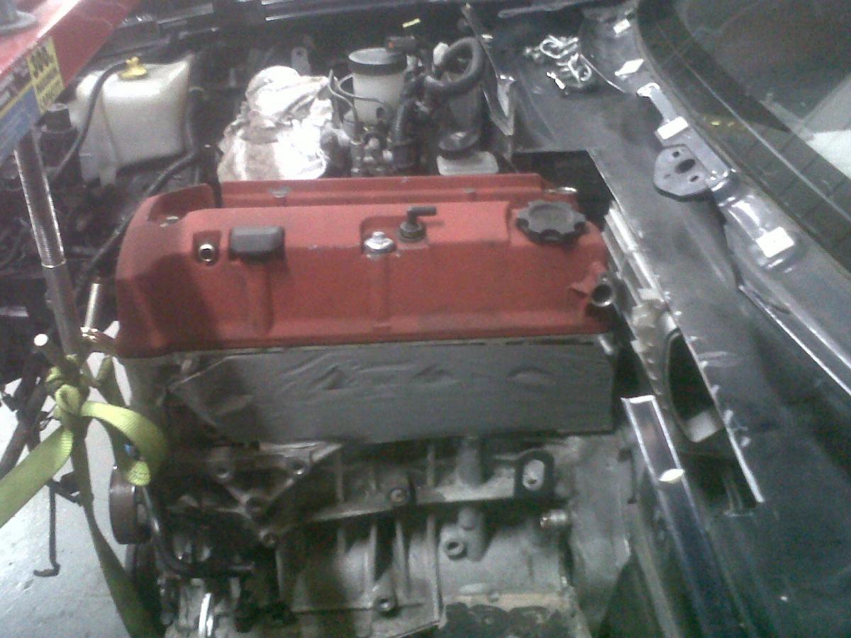
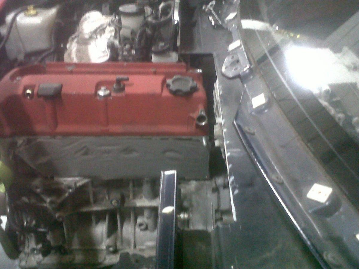
I managed to get over to the shop today for the first time in a week. The engine's in for the first time to check the fit. Turns out there's still a fair bit more cutting to do :P The engine also contacts the heater box, just. Basically if I want to retain a sane amount of clearance, I'm going to need to do something about the heater box, more details of which soon. Here are some photos from earlier today:
The galv tube is of a slightly larger diameter than the 'rack. As it sits, the engine clears it by approx 5mm.
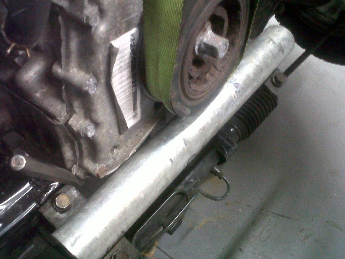
Appears to be touching in the pic above, but there's actually reasonable clearance.
I wanted the engine to sit low. A sump guard will be made if necessary, but bear in mind that this car won't be running much lower than standard '95 ride height.
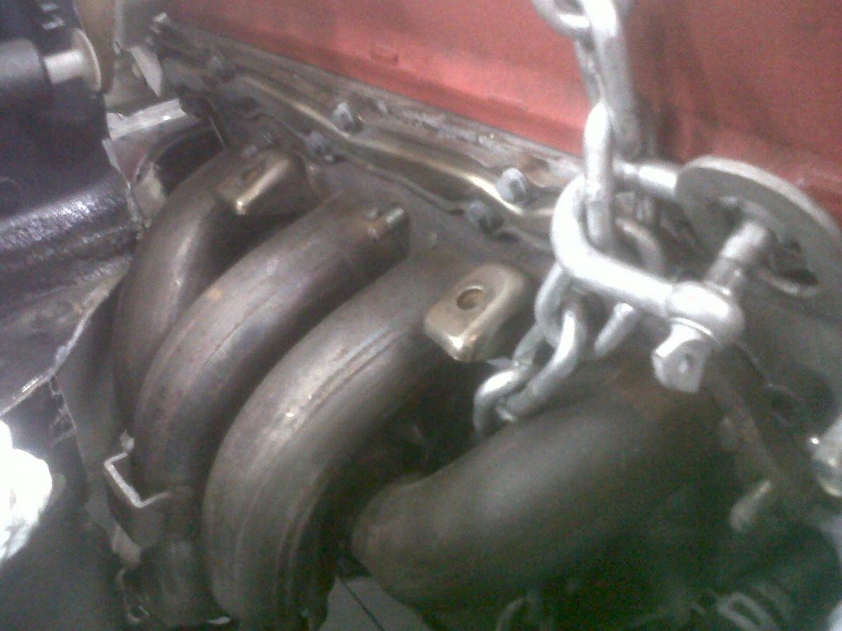
More cutting required to allow the exhaust manifold to be removable without dropping the engine. I obviously looked at it today, and in my humble opinion, there's plenty more material that can be cut away from this area on both sides, because the stiffness could be put back in with some carefully placed bracing. I told this to Steve, their machinist, who was the only one left there at the end of today, and he agreed, so I'll see what they do next week.
Oil cap may be plugged and moved to the front side of the valve cover at this rate. Worries about interference with the wiper mechanisms was mentioned.
The galv tube is of a slightly larger diameter than the 'rack. As it sits, the engine clears it by approx 5mm.
Appears to be touching in the pic above, but there's actually reasonable clearance.
I wanted the engine to sit low. A sump guard will be made if necessary, but bear in mind that this car won't be running much lower than standard '95 ride height.
More cutting required to allow the exhaust manifold to be removable without dropping the engine. I obviously looked at it today, and in my humble opinion, there's plenty more material that can be cut away from this area on both sides, because the stiffness could be put back in with some carefully placed bracing. I told this to Steve, their machinist, who was the only one left there at the end of today, and he agreed, so I'll see what they do next week.
Oil cap may be plugged and moved to the front side of the valve cover at this rate. Worries about interference with the wiper mechanisms was mentioned.
Reply
0
0

Use a manual rack and move the engine forward, most likely it will give the extra clearance needed for the heater box. The manual rack is much smaller in diameter than the power rack you have in your pics.
Reply
0
0
Thread Starter
Junior Member
Joined: Dec 2010
Posts: 375
Total Cats: 20
From: UK, in Cambridgeshire or wherever work takes me.
It is, but it's also a slower ratio. I'm having the power rack depowered and welded up like so: http://www.motoiq.com/magazine_artic...ring-rack.aspx
Reply
0
0
Thread Starter
Junior Member
Joined: Dec 2010
Posts: 375
Total Cats: 20
From: UK, in Cambridgeshire or wherever work takes me.
More cutting has been done. The exhaust manifold is on. Looks increasingly like I'll have to drop the front subframe assembly to drop the engine.... but that's fine. The bottom of the manifold sits about 30mm (I didn't measure it) below the frame rails, so it's pretty low. I spent ten minutes looking at the exhaust, and I think a side exit, just in front of the (UK) driver's side rear wheel, using an approx. 6x14 inch round muffler, is achievable. Side exit exhaust = less weight, and also..... erm...... well..... well frankly I just find side exit exhausts ridiculously cool, ha!
Apparently the main guy working on my car knows what he's going to do with the heater now, and it involves cutting into it, but not losing the flaps.
I can't think of anything else interesting/new to say right now and didn't get any pics (the shop is still taking copious amounts of photos as they go) so that's it for today folks.
Reply
0
0


Thread Starter
Junior Member
Joined: Dec 2010
Posts: 375
Total Cats: 20
From: UK, in Cambridgeshire or wherever work takes me.
The side exit shouldn't encroach on ground clearance too much. There seems to be enough room between the back wheel and the main structural part of the sill for a three inch pipe to sit level with the normal sill height. the muffler might hang slightly lower than the frame rails. So it's not like it's going to be hanging under the sill. I'm fucked for ground clearance anyway what with the manifold already hanging below the previous lowest point on my car, so sod it :P
Good job I hadn't planned on lowering the car much, huh!
Good job I hadn't planned on lowering the car much, huh!
Reply
0
0
Are you using the stock manifold? That thing weighs a ton. I used a DC sport header as a starting point, then modified it as needed. I will have to try and find my dyno sheet from when the car was na, Maybe I gotucky but my power was not compromised at all.
Reply
0
0
Thread Starter
Junior Member
Joined: Dec 2010
Posts: 375
Total Cats: 20
From: UK, in Cambridgeshire or wherever work takes me.
Yes I am. I hadn't budgeted for a replacement, which means (contrary to shlammed's GIF above) I don't have the money for a decent one. I originally hadn't budgeted for a replacement because the standard manifold is pretty well designed, as has been proven with a number of back-to-back dyno tests over on s2ki.com. Approximately half the well-known aftermarket manifolds either gain about 2hp, or lose power. The best (generally agreed to be Hytech, circa $1.5-2k) without touching the ECU, makes maybe 7-10hp at the most. If I was extensively modifying the engine I'd buy a manifold to match, but for a standard engine, the standard manifold works very well indeed.
Saying that, I hate excess weight with a passion, so by telling me the standard manifold weighs a lot, you've made me sad. Darn it.
Saying that, I hate excess weight with a passion, so by telling me the standard manifold weighs a lot, you've made me sad. Darn it.
Reply
0
0
Thread Starter
Junior Member
Joined: Dec 2010
Posts: 375
Total Cats: 20
From: UK, in Cambridgeshire or wherever work takes me.
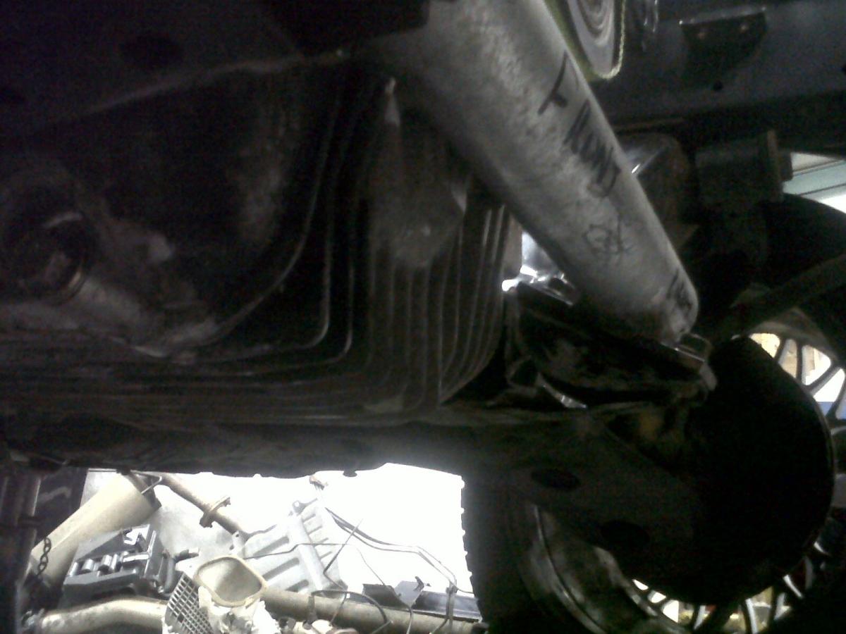
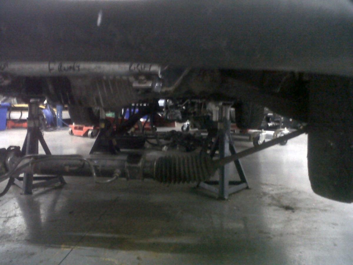
Exhaust manifold on. The manifold studs will be replaced with bolts to allow the manifold to be pulled without having to drop the engine. As it sits, there's no space to slide the manifold off the studs.
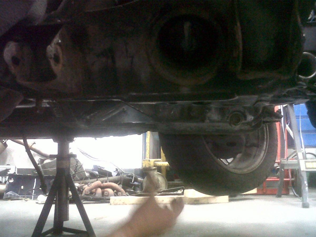
This is a **** photo, but I thought a **** photo is better than no photo (just) so I've thrown it up here. It's looking across the sump, and is to show that 1) the sump plug sits handily just below the chassis; 2) the subframe can be braced directly between the two rear lower wishbone mounts, and just ahead of the front lower wishbone mounts. Obviously it would be best from a structural point of view to be able to brace directly across from both of them, but the sump sits in line of the front wishbone mounts, so a section will be made that goes around the sump. But basically, it will be possible to brace the subframe up in a way that will make it probably stiffer than it was originally.
Also - the side exit exhaust will happen. The manifold donut gasket and the bit before the gasket (the....tertiary pipe?!) is being replaced by a slip joint, because it's lighter and means the tertiary pipe can be pointed in the right direction instead of off at a slight angle as it is at the moment.
The tran tunnel will be enlarged slightly. There'll be enough space for the pipe to flair up to 3" from the manifold, run straight back, then turn 90 degrees before the rear wheel, then have roughly a 6"x14" muffler. Then the exhaust will exit either just in front of the rear wheel (cutting into the angled non-structural sill part that's there), or exiting downwards with a slash cut. Quent thinks exiting it in front of the tyre is a bad idea because of the amount of heat it'll be putting into the rubber. I suggested wrapping the muffler and tip, and he countered by saying the wrap will very quickly get covered in crap after a few days of daily use. So I don't know what will happen with the exit yet. One thing's for sure though... it won't be quiet

Reply
0
0
Thread Starter
Junior Member
Joined: Dec 2010
Posts: 375
Total Cats: 20
From: UK, in Cambridgeshire or wherever work takes me.
It's handy working at a steel yard. Quent wanted a jig for the exhaust flair and slip joint just after the manifold. It just had to be a bit of tube with the same o/d as what I'm using for the exhaust. So I grabbed ten mins after work and used a bit of 304 stainless as so:
Giving it a quick polish:
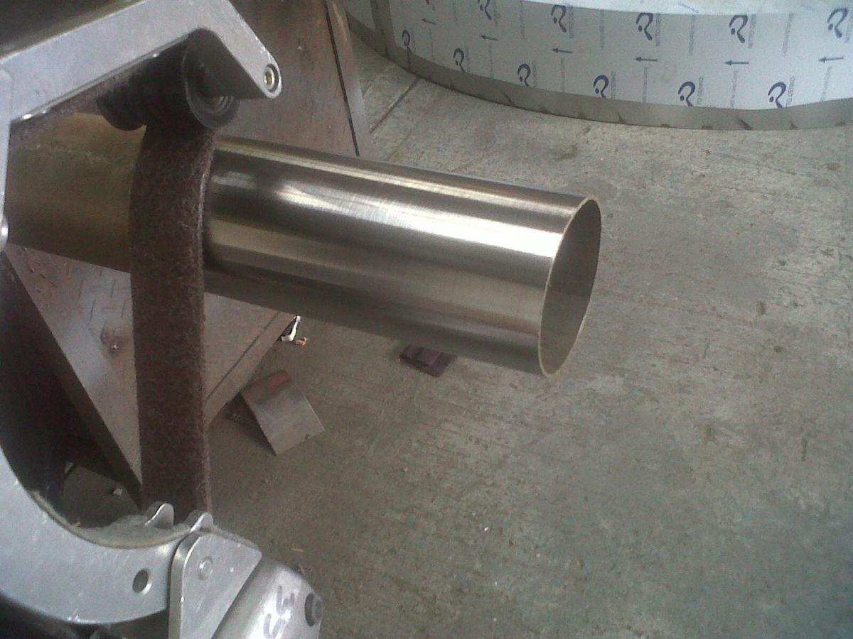
And bandsawing:
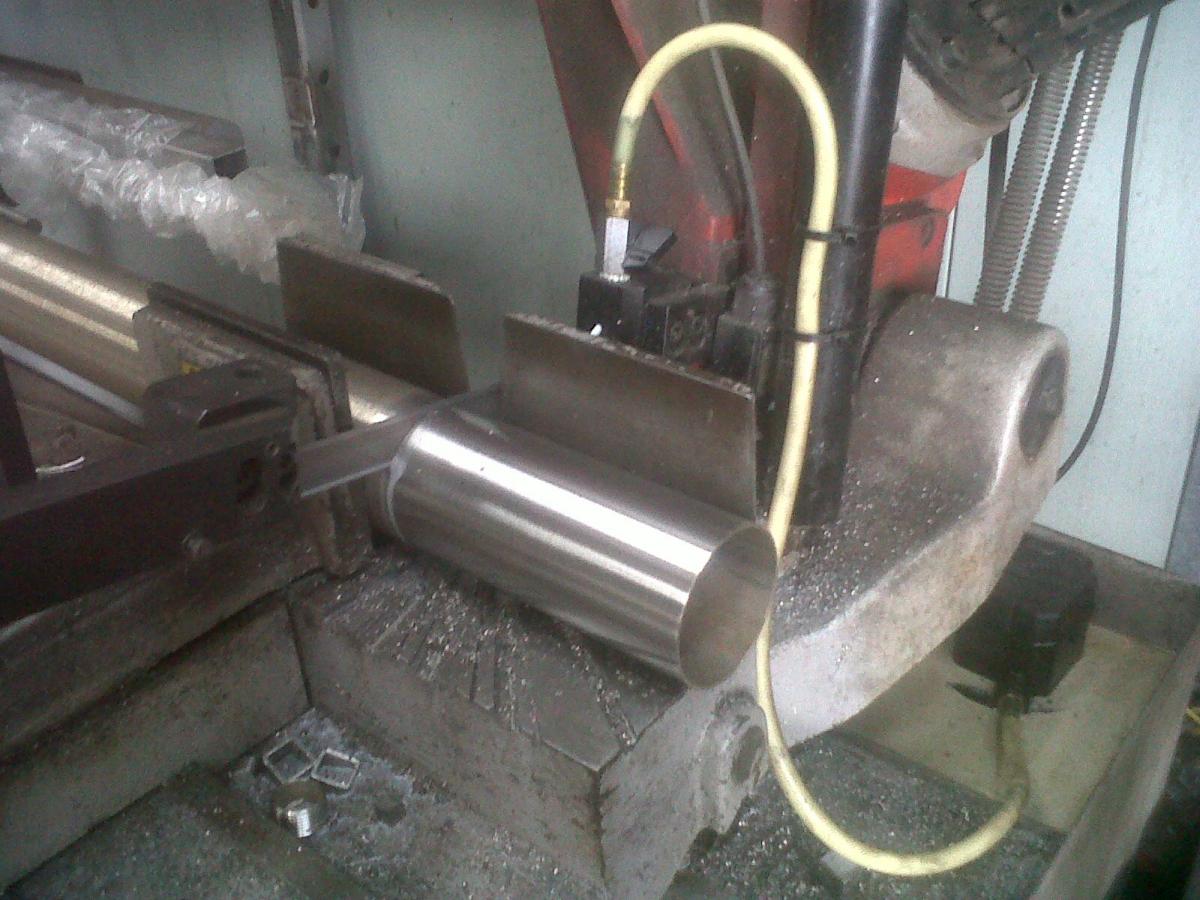
Then gave it a quick once-over with a 4.5 inch flap disk, and took it to the shop. So the exhaust manifold slip joint will hopefully be fabbed up this week, then I'll be making the exhaust myself.
Lastly, here is a photo of two ladybugs having sex.

Giving it a quick polish:
And bandsawing:
Then gave it a quick once-over with a 4.5 inch flap disk, and took it to the shop. So the exhaust manifold slip joint will hopefully be fabbed up this week, then I'll be making the exhaust myself.
Lastly, here is a photo of two ladybugs having sex.
Reply
0
0

Thread Starter
Junior Member
Joined: Dec 2010
Posts: 375
Total Cats: 20
From: UK, in Cambridgeshire or wherever work takes me.
I'd like your thoughts on seats please guys 
So far I've been absolutely set on Tillett B5s, mainly for weight reasons. The carbon/grp version weighs in at under 6kg (13lbs). http://www.demon-tweeks.co.uk/Motors...Seat/1761/1047
However, I just realised that Recaro Profi SP-Gs weigh near-as-dammit the same amount... http://www.demon-tweeks.co.uk/Motors..._Seat/1761/992
Suddenly, all that extra padding on the Profis is looking pretty tempting. I've experience of Caterhams with unpadded seats, and have sat in Profi SP-Gs. Both were comfortable, and I like the minimalist approach of the Tilletts, but I'm trying to imagine if getting into a big squishy Recaro every day would be more fun that clambering into a solid carbon bucket. So far I'm not sure. Thoughts, anyone?!
Reply
0
0
Thread Starter
Junior Member
Joined: Dec 2010
Posts: 375
Total Cats: 20
From: UK, in Cambridgeshire or wherever work takes me.
I'm going for Profi SP-Gs.
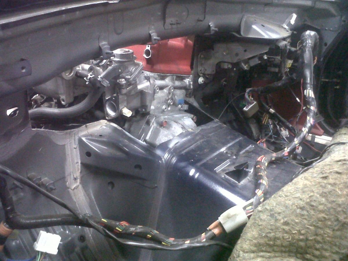
Engine mounts have been made, so the engine now sits where it'll sit. The proper rubber (rally-spec mounts, not sure what exactly they are called) hasn't arrived yet so it's still being supported by the hoist.
Final engine position. Not THAT far back really. Interestingly, it's not even as far back as the engine normally sits in an S2000. Still a fair few inches further back than the standard BP location though:
Note the heater box clearance now that the engine has been pushed further forward... interesting. With a few adjustments to a couple of sensor positions, minimal heater box disemboweling will take place:
Holy chopped up PPF !!!11!1!!!!!!1! (......obviously cut down to match the decreased distance between the gearbox and diff):
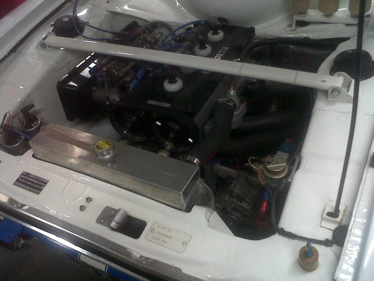
Any excuse to post a photo of the Cosworth BDA in this rallying Escort, that's in the shop again being worked on, is fine by me. Hopefully my engine bay won't look too dissimilar once completed:
Lastly, here is a photo of me in a dress looking like a douche.

Engine mounts have been made, so the engine now sits where it'll sit. The proper rubber (rally-spec mounts, not sure what exactly they are called) hasn't arrived yet so it's still being supported by the hoist.
Final engine position. Not THAT far back really. Interestingly, it's not even as far back as the engine normally sits in an S2000. Still a fair few inches further back than the standard BP location though:
Note the heater box clearance now that the engine has been pushed further forward... interesting. With a few adjustments to a couple of sensor positions, minimal heater box disemboweling will take place:
Holy chopped up PPF !!!11!1!!!!!!1! (......obviously cut down to match the decreased distance between the gearbox and diff):
Any excuse to post a photo of the Cosworth BDA in this rallying Escort, that's in the shop again being worked on, is fine by me. Hopefully my engine bay won't look too dissimilar once completed:
Lastly, here is a photo of me in a dress looking like a douche.
Reply
0
0


