When you click on links to various merchants on this site and make a purchase, this can result in this site earning a commission. Affiliate programs and affiliations include, but are not limited to, the eBay Partner Network.
Made some good progress this weekend but didn't take as many photos as I thought I had.
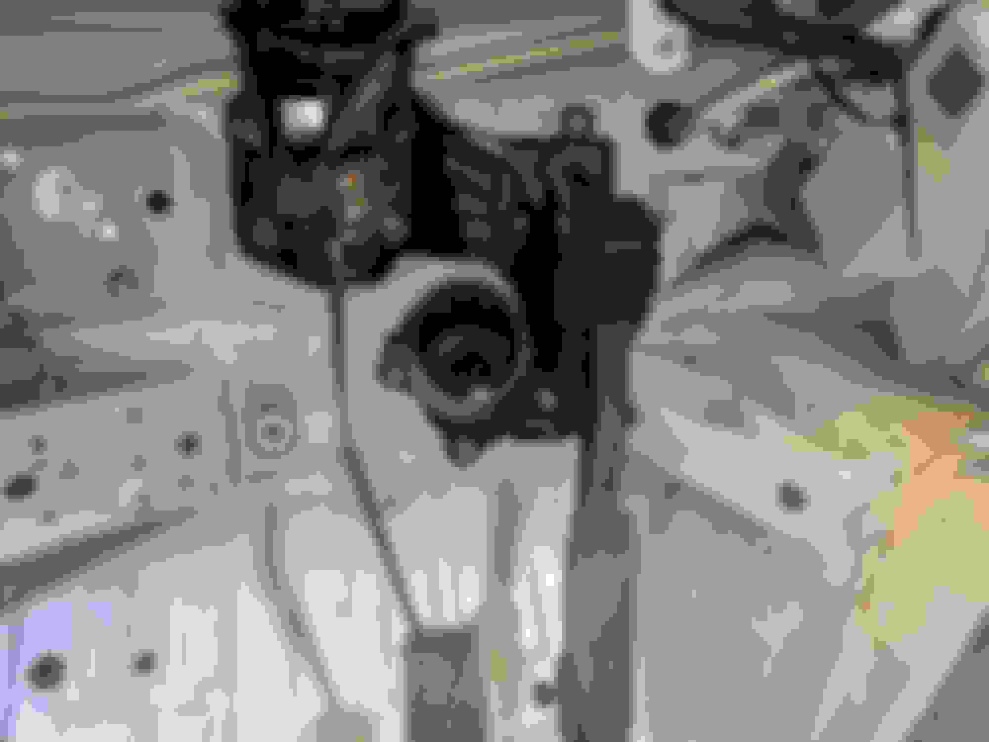
Here's the mounting stud that had to be trimmed back to clear the new accelerator pedal mount. Not a big deal, but a bit inconvenient. It would have been easier with the steering column out, but that ship has sailed. The bolt at the rack is easy enough to remove, but it didn't want to come out of the rack and there's a crap-ton of stuff in that part of the engine bay now. No damage was done, thankfully.
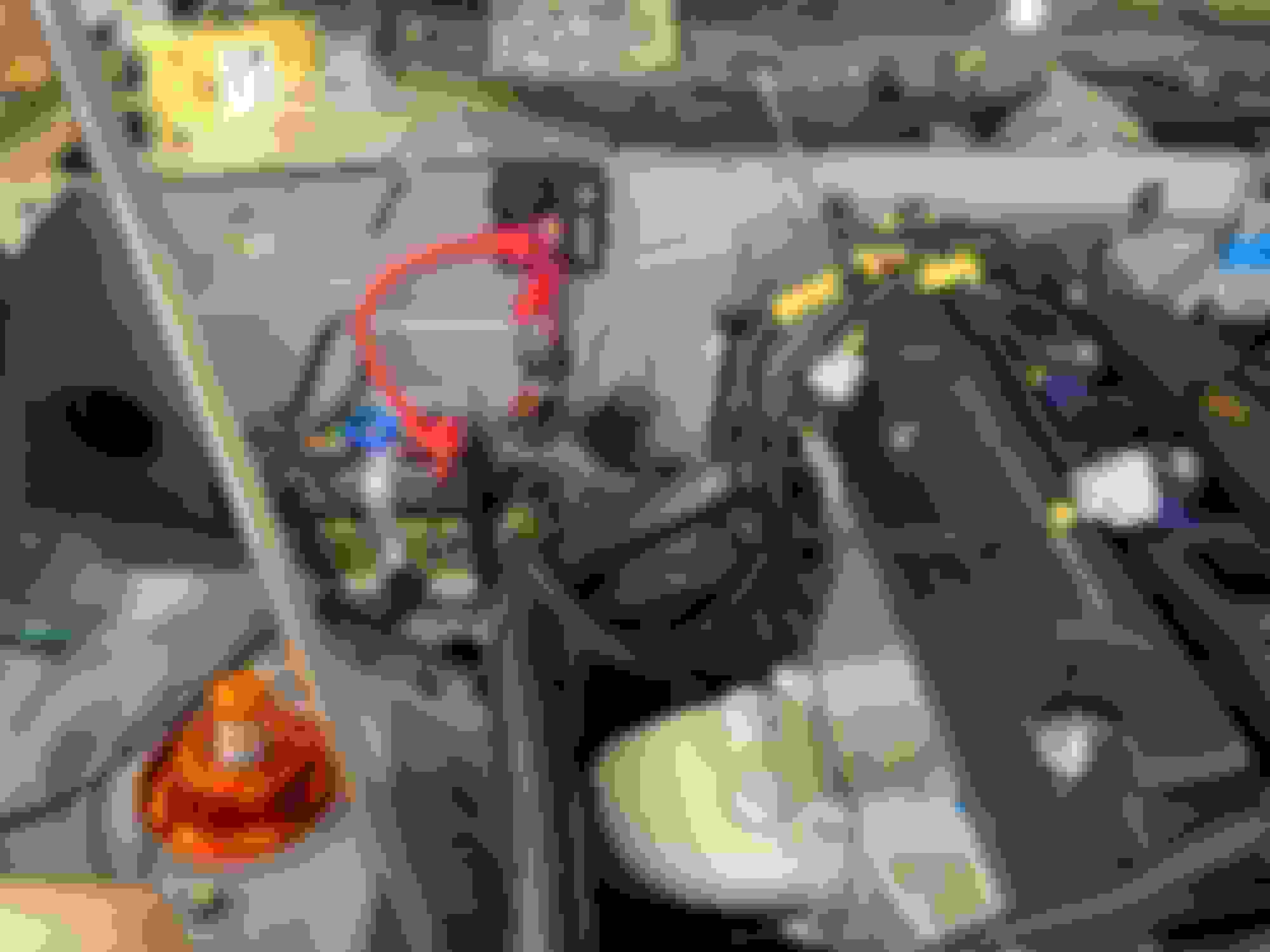
I gave the pedal assembly and steering column mount a blast of primer and paint. Here is the Subaru pedal in place, with the brake pedal mounted. I'm going to start with one return spring and see how I like that. I kind of want to create a floor-mount stop for the accelerator since it starts to flex the mount once it reaches the end of travel, maybe an inch and a half above the floor. I don't trust myself not to try to put the pedal to the floor.
Here's a look at what ($$) gets you for an oil pressure sensor. Same Honeywell sensor as the fuel pressure, NPT to JIC fitting, off-the-shelf 10" 4-an line by Fragola, JIC to BSPT fitting on engine block. Hopefully this is less susceptible to vibration than hanging the frankly massive Miata sensor off the block. Plus I get to transfer the original Miata sensor to my 96 when I get around to replacing the on/off gauge on that. So I saved money? Maybe?
Here's a quick tip you may already know but that proved useful this weekend.
If you want to clean up rusty or painted threads and either don't have a thread die or don't want to risk re-cutting the threads on a bolt/stud, cut a slot in a nut and use that.
If you check the title of the thread, you'll understand that I marked the position where the threading starts on the flange side of each nut. I then went forward four facets (or is it back..) and made another mark where I was going to make my cut. This gives about half a turn of engagement before reaching the cutting surface of the modified nut. I cut each nut through on my band saw and then used a piece of sand paper to file off the burrs. The band saw is prefect for this. If you're making anything with metal in your garage and haven't turned a portable bandsaw into a tabletop one, you're missing out on one of the best and most versatile tools...
Here's an example of how well this works. On the right, a painted M8 stud. On the left, a painted and partially-chased M8 stud. It takes a couple of passes, but works very well. I think I did another pass or two after taking this photo. Only paint came off, no steel.
I made myself chasers for M6, M8, and M10 in maybe ten minutes, including the time to overthink things. I ended up using the M6 and M8 immediately and tossed the lot into my thread-chaser bin in my tool chest.
I did not expect the supply-chain meltdown to be impacting this build, but wow, it is making sourcing parts for the wiring and connectors far, far more difficult than it should be. Instead of buying from one vendor, I've been spread across three different vendors, including Waytek. Their pages have been very useful and when I called about an item they had an ETA listed on, they were very helpful, but their prices aren't great and their shipping is expensive!
In the last two evenings I've placed orders for about $400 in stuff, everything from the fuse box to relays and circuit breakers. I think I'm still a few breakers short of a car. I ended up going with a fusebox that's probably 30% larger than what I need, but it's what was available. I'm also going to be rocking an orange Deutsch connector at the cooling fan because that was the only way I could get that size/configuration connector.
Knowing the problems we have at work with getting some parts, I guess I should have expected this, but Deutsch connectors and GEP fuse boxes? WTF.
We put a new fusebox in our e46 LD car this year and sourcing connectors, terminals, and the fusebox itself was helllll. Good to know it hasn't gotten any better lol
Saw you post link to this thread on FB. Thanks for all the info! Wish I'd seen it earlier, but still crazy valuable. I'm doing a complete Haltech harness. And while waiting for the kit to arrive I've had plenty of time to pull all unused factory wire from the whole car.
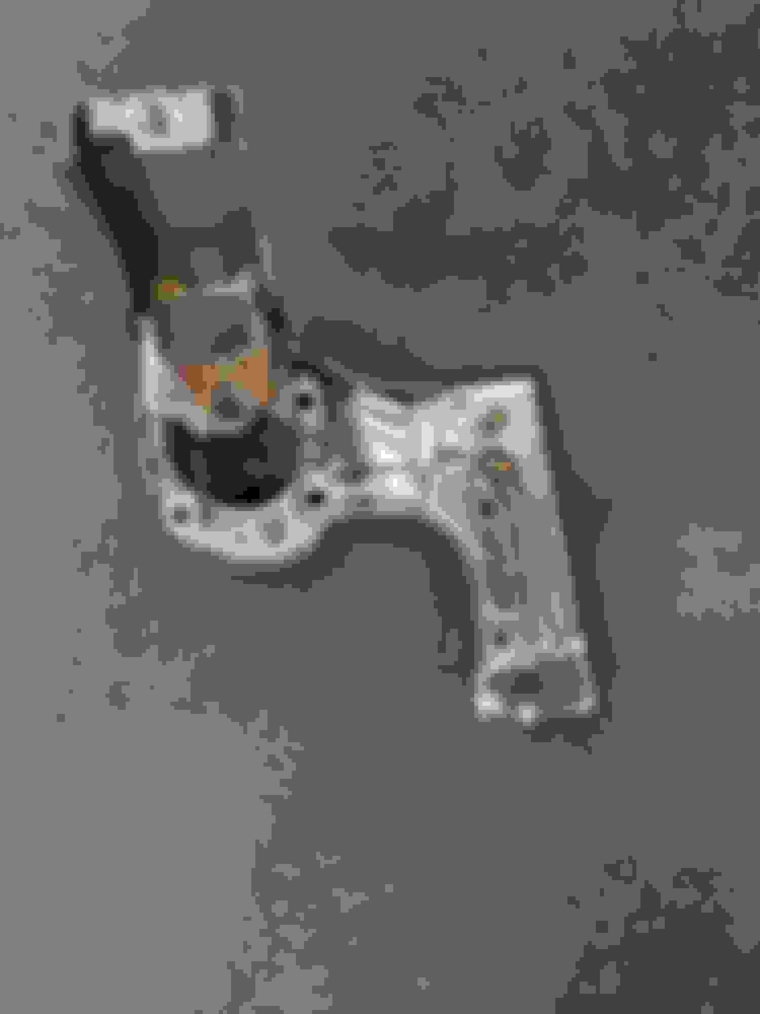
If anyone else is considering the NC/RX8 throttle, here's how my bracket turned out. Still working on my TiG skills, and this is all by hand... just a band saw, drill press, angle grinder, and cardboard patterns. So don't laugh too loudly. It's not pretty, but very solid.
(Not really shown: there's a little riser box to support the lower foot of the pedal at the correct height, which is removable to get at the lower mounting stud for the main bracket)
There was an error in the spreadsheet I used to calculate the amount of wire I needed for my harness and I ended up short of the white and red Tefzel. I also ran out of plastic sandwich baggies to hold all the cut wire sections, but that was an easy problem to solve even if it was disruptive. ProwireUSA was out of the red wire, so I had to order bigger lots than I really needed, from RaceSpecOnline, and pay for fast shipping to get it here before Thanksgiving weekend. It did give me a chance to measure for and order the Raychem SCL that I'll be using over the inline splices, so that's OK. Still, paying $30 for two-day shipping due to poor spreadsheeting hurts.
I also mapped my inventory of terminals to the sensor connectors I need to populate and placed another order with Ballenger. Thankfully the Honda stuff is almost entirely (and I say almost just because I'm sure there's something I've missed) the same "Sumitomo HX 040" female terminal and I'm using 20awg pretty much everywhere. I came up a few terminals short of a harness so I ordered a bunch more of those, plus the GM connectors for the temperature sensors - note that the IAT and CLT sensors use different connectors! I also ordered the connector I hope is right for the Impreza throttle pedal.
I plan to use the long weekend to power through some of this stuff - hopefully I can test-fit the engine harness by the end of the weekend and measure for the DR25 sheathing. Engine bay harness gets the fancy stuff, interior will get covered in TechFlex.
As of this evening, the wiring is complete enough that I should be able to start the engine tomorrow. That�s been the goal - engine running before the new year.
The fuse box is complete and wired in. Power is reaching the places that need it. Fuel pump goes whrr, the green light on the ECU comes on. I�ve measured the fuel level voltage for the dry tank so I can calibrate the fuel gauge on the Haltech dash.
I need to bolt on the intake manifold, then install the injectors, fuel rail, spark plugs, and throttle body. Maybe the wideband too. Fill the cooling system. Stage some fire extinguishers. Throw a splash of fuel in the tank. Turn on the fuel pump and adjust the fuel pressure. Then it�s the moment of truth�
I was held up by a fuel leak and a misplaced 5v connection. I thought the fuel leak was going to end the day but thankfully I ordered extra fittings when I did the fuel line plumbing. The 5v feed was a little more subtle to find but only required swapping two wires on the bulkhead connector. That was a stupid mistake on my part.
I had a few near-starts that each resulted in a comically large BANG out the tail pipe. I changed the TDC angle to the 36* indicated in Emilio's post and it actually ran. I had been using a value from another post that was closer to the alternate 396*.
It sounds like the base timing is off but that's a problem for another day. It runs!
I'm overall happy with the setup, but I wouldn't do it again, I'd go full-on PDM from Haltech or AiM.
The wiring of the fuse box ends up being a slog and impossible to make truly neat. I want to use circuit breakers instead of the standard fuses and those seem to be impossible to find in assorted values from one source - right now everything is either 15A or 25A. The 25A are acceptable for the wire size I use on those circuits, but the 15A breakers may melt some wire before they trip. I will say that the terminals were some of the easiest to work with, both in terms of getting a good crimp and being able to remove and reinsert easily. Just make sure to get the tanged terminals - the tangless ones don't hold unless you add the TPA doohickeys and have the proper seals - I didn't feel confident in them.
Here's the backside of the fuse box with most of the wiring in place. It's organized, but not exactly neat.
This is how I have used the fuse box. Having a bus bar to provide coil ground would have been nice, but I don't know how Bussman could have done that in a generic way.
These are the outputs from the microPDM:
To be honest, I'm not using the microPDM to its full potential. I have so few circuits left, it's pretty overkill right now. If I was running an enduro car or needed flash-to-pass, it'd be more useful. I think where it really shines is if you are using the stock wiring harness and relays and want to control the relays from a single, simple keypad.
I bundled the ECU/coils/injectors into one output because I just couldn't think of a reason I'd need to cut power to the coils or injectors separately from running the engine. I shared this in an earlier post, but I got there by listing out some "user needs":
It turned out that being able to control the fuel pump from both the keypad and the ECU was great for pressure-testing the fuel system. That was a need I missed, but thankfully had been covered by the need to pump out the fuel tank.
This is the breakdown of states for the electronics in the car:
Dead (Via kill switch)
No power
Cold
uPDM on
Keypad on
On
ECU on
Coils on
Injectors on
Fuel pump ECU control
Data logger on
Cameras on
Dash on
ABS on
The Haltech has a surprisingly large standby current draw, even with the ignition wire disconnected. 240mA with the ignition off, 280mA with it on. With my tiny battery, I didn't want that sort of draw in my "Cold" state, even if it would make ECU interaction easier.
That's a very long answer to a very short question - hope it helps.
Last edited by thebeerbaron; Jan 1, 2023 at 05:47 PM.
Reason: add url
If anyone out there is keeping track, the coil pack connectors, including pins, are not compatible between the TSX and Accord.
Sigh.
I discovered that I had a bad coil when I went to check the base timing on the engine. That was fun - I blamed the ignition wire, the timing light, etc. Nope, bad aftermarket coil. The roughness I was hearing was not (entirely) due to bad base timing.
Acura coils aren't cheap and RockAuto doesn't carry Denso versions of the TSX coils, so I went down a rabbit hole and ended up thinking the Accord and TSX coils were the same. They are not. The connector doesn't come close to fitting and the pins on the TSX coils are a smaller size than the ones on the Accord. I can't retrace the logic that got me to this incorrect conclusion, but here I am. I have four brand new Denso K20/Accord/S2000 coils that don't fit my wiring harness. I ordered some cheap replacement connectors from Amazon - they'll get here Saturday.
Note that the Ballenger part CONN-100327 is marked as the K24 application, but I don't think it would fit the TSX coils.
edited - no, I simply screwed up and ordered a part for the wrong year Accord.
Last edited by thebeerbaron; Jan 6, 2023 at 12:16 AM.
Guess who just poured half a quart of expensive Motorcraft XT-M5-QS out onto the garage floor?
Yep, that'd be me.
I started to fill the trans from the turret, forgetting that I had taken out the speed sensor. I was basically pouring the oil over the shift mechanism and out onto the floor. Much cursing ensued.
After that, I finally got around to cutting off the old speedo connector and replacing it with a DTM-2. Shoved the sensor into place, bolted it up and dropped in half a quart to see if there are any leaks.
Now I just need to order another quart of unicorn blood. Curses.
My goal this weekend was to put the driver�s seat back in and make the panel for the CAN keypad and driver�s kill switch.
Side project #1:
Stripped the driver�s footwell and laid down strips of grip tape. A heat gun on low really made it pliable and easy to contour.
Side project #2:
Made a small steel mount for the Solo 2 DL. I�m using the stock magnets for now, but as soon as I find the screws, I�ll throw a couple in just for backup.
I did eventually get the center stack all bent up. I still need to drill holes in the dash structure and throw rivnuts into the aluminum, but that�s a task for another day. I can hit all the keypad buttons and the kill switch, yet they�re nowhere near my hand when shifting.
Side Project #3:
I decided to plumb in the brake bias adjuster for the MK60. It�s there if I need it, but I intend to let the MK60 manage the bias.
Also, there�s now fluid in the brake system. Found a leak and I think it�s now fixed. I really hope it�s fixed.


 0
0