When you click on links to various merchants on this site and make a purchase, this can result in this site earning a commission. Affiliate programs and affiliations include, but are not limited to, the eBay Partner Network.
I almost made the same mistake with a Rockauto ecu for my ecotec swap. Thankfully I caught it in time. I did make the mistake of buying two ebay V6 ECUs though, which can't be reflashed to work with my 4cyl. Not sure if they'll work for you but I can send you the VINs. I think I've read that you're supposed to use a manual trans ECU for the LFX swap, but everyone uses auto ECUs for the Ecotec.
I just dont know what works. Doesn't seem like there should be a secret combo. Anybody with a properly functioning car have a GM service # that they know works? the junk yard only has so much patience for me picking through what they have but they do have service # listed
Unfortunately, you can't go by service #. A service number basically means it "can be flashed" - via gm tools - in a GM vehicle - with all the can-capable modules, ECM, BCM, FPCM, ABS, and even the radio - to the firmware that fits that specific vehicle.
It's a right pain in the dick.
This is GM's "Global A" program, meant to stop those dastardly car thieves and aftermarket parts recyclers.
It's meant to be a pain in the dick.
E38 ECM's, what you use in V8's, can be "bench flashed". Lots of ebay vendors can recycle Sierra truck ECM's and reflash them to Camaro ECM's - again, based on the service #.
I snagged our ECU(s) from lkqonline.com - the search is terrible, and if you call a CSR on the phone they don't really have any additional tools to help. But - again - you need to make it very clear that you want *that* specific ECM. I had to go through their terrible site, find an ECM with the proper VIN (a lot easier than trying to determine what the shfiter is in the picture of the car), then write down the specific part number, and call lkq and say you want *that* specific ECM. First manual ECM I ordered - turns out it went missing (junkyard inventory tracking is difficult), and 5 weeks later they sent me an Acadia ECM. To their credit, they sent me a correct one once I called up to complain (and I had the *specific* lot/vin/yard number).
Either that, or grab it from v8roadsters. We went the hptuners route since we were doing 2 cars.
I tried to get it from V8R but they were reticent for some reason, something like "we can probably do that". Dunno
I got HP tuners too because I'm like that. In the absence of knowledge I just ordered 2 ECUs today, both from 3.6l manual Camaros. One is a 2012 and the other a 2015 (same year as my motor) .I hope one of them works out. Car is done save for an ECU and exhaust
I just ordered one from a manual trans 2012 car matching the service tag cited on the V8R site. Asked them to verify that it's an E39 before shipping. Fingers crossed.
Hey I got an ECU form LKQ that cranks my car! 2012 Camaro automatic, E39 Serv#12643248. I still have 2 more on the way from manual cars.
Car cranks but no fuel or spark. I disable VATS 1 and 2 in HP Tuners and wrote it back to the ECU. I show 60psi fuel in my line from the tank just before the motor. Any tips to get that magical spark?
Just remembered I dont have O2s plugged in yet, BRB
Hey this is jeremy i talked to you at matg this year and you said to get with you and youd send me the gm wiring digram for my lfx build im working on thank
Alright - so this is long in the making, and it's pretty intimidating to do - much less to write up. So what I thought I'd do is try and chop this up into three parts and make it slightly more generalized so you can follow the same basic methods for LFX and LSx swaps - with the added experience of wiring my LS3 and implementing a bunch of lessons learned. When I originally wired the LFX I tried to follow the OEM wiring as close as possible and made it overly complex - but it works and there isn't any real benefit to going back and changing it (other than making it prettier and a little easier to manage) to how I've done it in the LS3. And a quick disclaimer - doing your wiring wrong can lead to damage or fire, so modify it as your own risk.
Part 1: Knowledge, Tools, Parts
The decision to make your own harness is probably driven by economics - but lets make no bones about it, if you're doing a single car by the time you get all the tools, wire, fuseboxes, relays - you're probably going to break even on buying a pre-made harness. And the time.. Oh lord, the time it takes - for the engine harness it's really not bad. But if you're insane like me and you've taken all the "stock" ecu wiring out, we're talking literally weeks watching netflix with the harness spread out on the floor tracing wires. I rewatched Breaking Bad, Futurama, 5 seasons of Cheers.. a lot of netflix while going through and depinning and removing wires.
I'm going to assume if you're undertaking this you have a basic knowledge of relays, diodes, crimping, and reading a wiring schematic. If you don't know, you should learn. Do not rely on the mellens wiring guide - the Mazda schematics are *way* more detailed - and if you choose to do the insane removal method, you'll need to look at the harness interconnects to depin the wires effectively.
For the LFX and LS3 - you need to make a handful of connections between the ECM and the Mazda side. In the LFX I stuffed the harness with a few extra connections like the clutch and brake position sensors - but found later that it wasn't needed.
Starter
Alternator Excitor*
Fuel Pump Relay
Throttle Pedal (6 wires)
CAN Bus (2 wires)
A/C
Battery Backup
Powertrain Relay input*
Simple, right? I'll cover these in Part 2 - GM Harness modification.
Tools
I actually have a toolbox that's filled with crimpers, pins, wires, taps, heatshrink, fuses, relays accrued over the last 20 years, from my initial stereo installation to megasquirt 1 2 and 3. It's really, really easy to spend a lot of money on high quality tools - but if you're a home gamer, you can get away with using cheap stuff so long as you're prepared to cut off and recrimp if it doesn't look right. And frankly - if it doesn't look right - you need to redo it.
Crimpers
$22 Basic ratchet open barrel crimper used for butt splices. I had to replace mine after the old one (that's done 10 years of service in the box) started loosening up and splices wouldn't pass the post-crimp tug test. Got this one at Summit.
Shame on you if you use this type of crimper. It'll work for stereo installs, but man it sucks.
$32 Tool Aid 18930 - used for weatherpack and metripack terminals. This one has been in my box forever - and it's not great - but it works. I originally got mine at Autozone, this one is available through amazon.
$55 Harbor Freight 66150 hydraulic cable crimpers. For battery cables and lugs.
Extractors
$7 Pico Pin Extraction Tools 0660PT
Again, been in the box forever, from summit. I used a number of weatherpack connectors on my megasquirt install, and the yellow extractor makes it waaay easier to remove pins.
Another bunch of pin extractors useful for the mazda harness. I got these for $1 off of ebay, but it took 3 weeks to arrive.
Harbor freight #1816 - $4 - really fun to go into the toolbox and get stabbed by one of these.
Cutters / Strippers
$4 Harbor Freight 90708 - flush cutters are really nice to have, if a little fragile. I have 3-4 of them, one in each toolbox.
$25 Klein Tools D252-6 Diagonal cutters. I splurged and its nice to have a good pair.
$7 Harbor Freight 40507 cable cutters. Useful for cutting the battery cables.
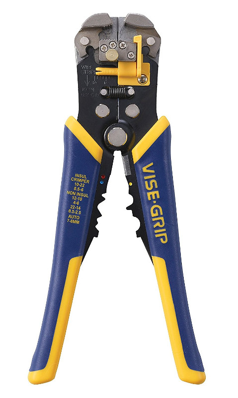
$23 Irwin Auto Wire Strippers. If you're using cutters for wire stripping, you probably haven't stripped enough wires to know that this tool is just plain better.
Deloomer
$3 A seam ripper is *really* useful for cutting the tape along split loom and has way less chance of damaging a wire than a knife / cutter. Wal-Mart/JoAnns/Michaels. Any craft story.
Parts
Amazon, Ebay, Summit are all pretty common suppliers. Waytechwire is also really useful, but they have minimum purchase order. A *lot* of stuff came from Delcity.com - really pretty happy with their shipping time and prices. Motorcycle Terminals, Connectors, and Wiring Accessories also has a lot of spiffy connectors and a really good crimp tutorial at Crimp-tool-help and Open Barrel Crimp tools
Loom
$15 Taylor Convoluted Tubing 38000
10' of the common sizes. For longer sections (like 1/2in) we supplimented with ebay to keep the price down. After my adventures with different types of loom, the boring stuff that the OEM uses works really well.
Harness tape
Electrical tape is not the same as harness tape. If you use a quality electrical tape like 3M Super33, it'll turn into this sticky, nasty, icky mess after a couple of years. Elliott Tape ETN1000E came from ebay and was $4 a piece - ended up using 3-4 rolls up between the two cars (though to be fair, also ended rewrapping up looms a couple of times as well.)
Wire & Cable
Wirebarn.com has various lengths and gauges of TXL/GXL wire. TXL/GXL wire is the really nice sheath that's oil and temperature resistant and is what the OEM GM harness is made of. 20ga is thick enough for most of your signal needs, like the throttle pedal and canbus wires. 8ga (though I'd prefer 6ga) was used for alternator and starter to fusebox connectioins.
We snagged 35ft of 2ga TEMco welding cable for our battery cables - if I remember right, it's roughly 12 feet from the battery to the starter. Since the PPF is removed, we ran a dedicated ground wire from the battery to the engine as well - so 24ft - but 25ft might be cutting it a little tight - and the ebay seller didn't have a 30ft option. Since the LFX has the starter on the drivers side, we ran the positive cable to that side through a bushing and then along the frame rail. It looks like prices have jumped since when we bought it.
Fuse Box
$40 EATON's Bussmann 15305-2-2-4 Mini Fuse Panel. Purchased from delcity. Holds 5 280 ISO relays and 10 ATM fuses. There are different versions that are fully individual vs partially bussed. For the LS3 I used the fully bussed version, but used the individual pins in the LFX. Fully bussed means you can't do nifty tricks with diodes and will need something to hold those.
Metripack 280 Tangless Terminals
$70 - Terminals for the above fusebox. More than enough to build 2 boxes, again from delcity.
Auxiliary Box
Sealed Mini Fuse Panel with individual inputs - good secondary holder for additional non-bussed fuses or diodes. Uses the same tangless terminals. delcity.
Metripack 150 Kit
$70 - Really like using these connectors, they're OEM for GM vehicles, so I can always go to the junkyard and pocket a few extra shells easily. They're also really easy to depin (with the appropriate terminal tool). I used these for all the interconnects - but they're only rated for 15amps. Ebay.
Powertrain Relay
$30 from ebay - Cooper Bussmann Power Relay Module 37702-1AN0022
Make sure you get a kit with the terminal pins and connector for the relay control. Very simply - this is your main relay that provides all the power for the ECM, injectors, and fans - so it's beefy. I didn't use one of these in the LFX and it made the wiring complex, since the ISO280 relays are typically only rated to 25a, so I ended up reusing the miata's relays to drive the fans. It has 2 Maxi fuses (one for the always-on stud and one for the switched stud) so you can fuse your battery connection.
Wire protection
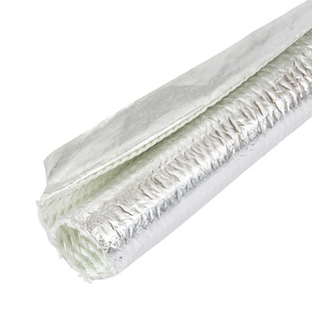
$13 for 1/2in x 4 feet. Thermashield heatshield wrap, using this where the headers run real close to the starter and ground cables. Nice stuff, has held up well in the 2 years. Adhesive holds pretty well. delcity
Fusion Battery Terminals
$7 (apiece) Solderable battery terminals - these are really pretty nice, but you'll need a torch to heat it up and then jam the cable in. delcity
Cable Management
Lots and lots of 1/2in cushion clamps for the battery cables and these little zip-tie push mounts are nice, again from delcity.
Labelmaker
A basic Brother P-Touch label maker works really well when you fold the labels over the cable like a flag. The label is plastic-y, and even after 2 years in the engine bay the majority of the labels are still attached and legible on the LFX. I used to label wires with avery labels, but they don't last long and get smeared and fall apart pretty quick. The main complaint I have with mine is it would chew through AAA batteries, but I hacked in a barrel plug into mine and now it works perfectly. Really amazing what a relatively cheap $20 printer can do.
Heatshrink
I'd not used this product before - but it's the bomb. Triple Wall heatshrink - it gets extra thicc, and the inner layer produces an adhesive that helps keep oxidation away from your crimped connections. Again from delcity - cheap, they sell it in 6inch sections. Suggest you get them color coordinated for the battery terminals and the 8awg size for the alternator connectors.
Heatgun
$15 from HaborFreight. Don't use a lighter for heatshrink. Heatguns are really useful for things beyond just heatshrink.
Copper Lugs
Easily available and cheap, to be used with the hydraulic crimper. Cover them with the triple wall tubing for both strain relief and corrosion resistance. 5/16 was the most common hole size for the 2awg cable, also suggested to pick up a handful of 8awg lugs off of ebay for the bus terminals (alternator, starter, powertrain relay, etc).
Insulator Covers
Just extra protection from the wayward ratchet - make sure you get one for the battery terminal and the alternator bolt. Amazon.
Butt Splices
Eventually, you'll need to connect two wires together. Cheap nylon splices work okay in the interior, but for anything in the engine bay a good heatshrink butt splice should be used, preferably with adhesive that'll help prevent corrosion.
I think that's mostly everything needed to tackle the rewire. Adds up pretty quick, eh?
Last edited by gooflophaze; Sep 19, 2018 at 06:27 AM.
Great post. As I've moved and more into doing my own wiring correctly, the biggest thing I learned and pass on to other friends is to buy the correct tools early on. They pay for themselves in less headaches down the road. I'll save this post for future reference (I always need better tools) because the insulated splice crimper I bought just isn't cutting it.
Very exciting to see someone put so much detail into just the parts/tools list alone and I am sure that the wiring instructions will be great! Very well done so far sir and I think I speak for everyone who has an LFX project when I say Thank You!
My turbo lfx buggy is almost complete, I have to hook up a hand full of wires for my switch-pros panel like the starter solenoid, fan power and then I will deloom my engine harness and begin the pinout process! All that�s left before the maiden voyage after wiring will be coolant, bleeding my pedals, loading a base tune and filling the tank up with some corn fuel!
The OEM GM harness is fairly modular - the engine harness has 3 connectors for the ECM and 2 interconnects that connect it to the rest of the car. X50 connects to the fuse box, X102 connects to the body. In general - all Pink/Black wires are fused and switched. There's a single Red/White wire that acts as the ECM battery backup (Circuit 400) that needs to run to a fused connection that's always hot. The easiest way to make this connection is to tap into the stock miata fusebox that I'll cover in the next section tentatively titled "Miata Wiring"
X50
This is where your labelmaker comes in since most of your wires here are pink/black. I labelled the wires six-ish inches from the end of the connector, then cut the wire flush with the X50 connector trying to retain as much length as possible. On the LS3 I ended up extending these wires out three-ish feet to open up some mounting options for the fusebox. Whenever you do a bunch of wire splices, it's good to stagger the splice placement so you don't have a bunch of splices in one spot that you can't get your split loom over. If you do lose a label it's not difficult to figure out what it connects to - find the pink/black wire on the connector for the description and check continuity. Once you have your fusebox position and your wires cut to length, it's time to make some decisions - Combining wires will lower the number of fuses necessary, but make it more difficult to troubleshoot and possibly less reliable. In the Bussmann fusebox, you have 10 fuse and 5 relay positions. Manual transmission is going to use 8 fuses - with 2 additional fuses needed for the fans which'll fill up the box. An auto will need a few extra fuses for the TCM. If you combine F14UA with F8UA, you can drop it down to 7. You can further simplify by combining F5UA and F20UA - generally, anything that has a low fuse value. In our setup we ditched the post-cat O2 sensors. The brake vacuum pump is ditched - it's controlled by the Camaro's brake control module, so the ECM doesn't have any control of it anyway. Furthermore, the Camaro uses a push-button start that's controlled by the ECM to engage and disengage the starter motor - since we're using the Mazda key, that can be ditched as well.
On the bussmann "bussed" fusebox, there are 2 studs - one for the fuses and one for the relay coils. For this I used the 8ga wire from the "powertrain relay" to the fuse side of the fuse box, then jumped that wire with a 20ga to the "relay side" of the fusebox. The relay side is only feeding the positive side of the relay coil (86 terminal) - so not much draw. A better, safer method would be to use one of the fuses to feed the relays. (1) in the image below.
Wiring the fans is probably the most involved bit. The GM ECM has a fairly complex method of fan control that I'll probably need to cover in a 4th HPTuners part - but the short of it is there's a high fan and a low fan relay. In the LFX the High speed setting grounds both the low and hi speed fan relays, in the LS3 they're triggered individually (IE, high speed doesn't turn on the low speed relay). In addition, some planning is needed to run this for the A/C so turning on the fan doesn't engage the A/C Compressor. This is done with diodes - either soldered in line (ew) or snagged from the junkyard in handy mini fuse form.
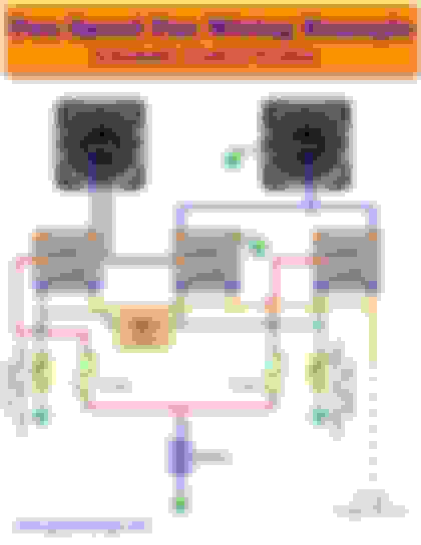
Fans in the easiest form - low relay turns on one fan, high relay turns on the other. Simple. Downside - airflow reversion - hot air is sucked back through the non-running (assuming common shroud) fan instead of across the heat exchanger. Two speed fans are accomplished one of two ways in OEM forms - either a gigantic resistor, or running the fans in series/parallel. Series/parallel require a 3-relay setup. To further complicate things, I decided to add another feature to help cut down on inductive kickback in the form of a reverse bias'd diode. Not 100% necessary at all - but I figured I had the extra spots in the auxiliary box - so why not? Here's the basic 2-speed fan setup with a handy graphic from Automotive Electric Fans | GTSparkplugs
That said - here's the schematic I drew up for how I wired up the fans in the LS3 and LFX. I know ya'll probably aren't EE's, but this is the best way to show the information (Please don't make me bust out MSPaint). For absolute clarity - if you see a line cross over each other but there isn't a dot, THE WIRES ARE NOT CONNECTED TO EACH OTHER. I included the extra fanciness of the snubber diode - this prevents a high voltage spike from occurring when the fans are turned off. NOTE THAT THEY ARE PUT IN BACKWARDS of convention - if you orient them in like you would a normal diode (with the banded end to ground) they'll short to ground and burn in no time flat. To learn more about it, google "inductive kickback".
You can also see the "AC_FAN_INPUT". So I guess now is a good as time as any to talk about air conditioning. Here's your basic circuit -
You push the A/C button, it completes the circuit from the 12v on the relay through the pressure and thermoswitch. I hacked in an extra wire onto the thermoswitch - this basically means even if the A/C pressure/temperature conditions aren't met, it will turn the fans on high (good for an emergency overheating situation, as long as you pull the AC Clutch fuse so that doesn't warm up the condenser as well). This is a dumb system - most ECM's like to know if there's additional load on the system so it can compensate at idle, and also turn off the a/c compressor while you've got your flooring it to give you that extra little oomph to the back wheels. So far I've only had it stall on me once when the A/C cycled at a stop light. Optimal? no - but you know what's awesome? Cold air. The diode on this circuit is absolutely critical (in the fan wiring schematic) - otherwise, when the ECM commands the hi fan relay, it will also engage the A/C compressor. The diode on the A/C button in the above schematic that goes to ground is built in to the HVAC panel.
Tips for wiring this mess: For the GM pink power wires that you're going to be combining, strip excessive length, twist together, cut to length, and then go up a terminal size and crimp (ie, if you're putting 2 14awg wires together, use a 12awg terminal). For the fans - use at least 12ga wires to the fans - but don't fall into the trap of overengineering and think that 8ga gains you anything.. For the snubber diode I crimped a 20awg wire along with the 12awg relay output (3). For the gndsw_relay and the hi_relay - just join the wires together 6-ish inches from the terminals with a heatshrink yellow butt splice and then run the 12awg wire to the radiator fan (2). Relay coil wires, diode pigtails, data wires - they're not carrying much current, and 20-ish ga wire is fine to the aux box (4). On the LS3 I did fuse the relays with a 10a fuse (1).
That's X50 and the fusebox mostly out of the way. Now on to..
X102 "Forward Lamp Connector"
This is most of what you need to integrate into the body - and most of it can be removed. None of these wires are really high-current carrying, so 20-ish awg wire is fine. This should be pretty self evident, but I'll add in some notes to address any questions.
Wires you'll be keeping:
440 - this is your battery backup for your ECM. Ideally this should be fused - but it's really easy to tap off of the stock miata fusebox (next chapter).
419 - MIL Lamp. Goes to ground when "on" - so you put a bulb with switched 12v+ on the other side of it. Illuminated with key on engine off and when you've got a code thrown. Can also be manipulated with HP Tuners for testing purposes.
2500 & 2501 - Needs to be run to an OBDII connector. CANbus wires are often twisted together - they don't *need* to be. There's a much longer conversation on the advantages of twisted pair in an automotive environment - but canbus is incredibly resistant to noise and for the length of the wires being run, you don't need to twist them.
Pedal wires - next section.
Wires you're removing:
380 - A/C refrigerant signal - instead of the 3-way switch that the miata uses, the Camaro uses a fancier 0-5v signal that the ECM monitors. The ECM takes this data along with a signal from the now-removed BCM in order to control the compressor clutch. Either way, out it goes.
5985 - Serial Wake Up. This is part of the can bus system used for the Camaro security system and a few other things - but it's not needed for OBDII/HPTuners/Torque.
5380 - Clutch Pedal position sensor. The Miata uses a clutch switch for stuff like disabling cruise control - the Camaro uses a 0-5v sensor. I did run this wire out to the interconnect to add in a sensor - but the car runs fine without it.
465 - I originally wired this up to the miata's fuel pump relay - and it didn't do anything. I did roughly the same thing with my LS3 - and it didn't do anything. Then I learned that on the LS3 this wire actually provides +12v instead of ground to the relay - so I modified my miata's FP relay to make it work. I still have this wire in the harness on the LFX and will hopefully get around to investigating if this can be run like the LS3.
The metripack kit I linked earlier annoying doesn't come with any 6 pin single row shells. Furthermore, they sell on ebay for $20(!) a pop. Run to the junkyard and snip one off of virtually any GM car with an electronic throttle. One of the easiest mistakes to make when wiring this is putting the pins in mirrored! On the connector shell itself there's often an "A" or "F" molded into the black plastic - use that to make sure you're in the right pin. The crimps need to be absolutely perfect - take your time with them, redo them if they don't feel right. The ECM is real sensitive about the pedal inputs, considering the liability of a runaway car - so it will disable the throttle if it detects any fuckery.
Using the Torque app for android and a cheap ELM327-based bluetooth canbus reader has been awesome to help diagnose without needing to drag the laptop out. The downside of the standard OBDII port is that it's run straight to battery - so your bluetooth radio is running whenever it's plugged in.. In the LS3 I changed pin16 to connect to a switched power source, so it's not draining the battery and I can leave the OBDII dongle plugged in. The other GMLAN stuff listed here are for "extra components" that we're not using. In theory, you can grab and OBDII connector out of any car and make it work if you repin it. Just make sure it has both grounds, a power, and the 2 can bus wires.
To convert an automatic harness into a manual harness - you need to add in the VSS connector and Reverse Lamp connector, and remove everything else. I ordered "Bosch 1 928 402 868 3 Way Connector Kit" from ebay for the VSS connector. The reverse connector is your standard weatherpack 2 pin connector and will be wired directly into the miata's harness to power the reverse lights (I don't know why the ECM wants to know if you're in reverse). Once you've got those added into the harness, all you have to do is to depin and remove everything on the round Q8 ATX connector. Pretty simple to do.
The K20 connectors are pretty easy to work with. To repin/depin one, first thing thing is to pry off the TPA (Terminal Pin Assurance) with a small screwdriver.
Then remove the backshell by prying the 2 tabs out of the way.
Then pry the locking tab out of the way while pulling on the wire from the back. It's hard to get a picture - but should be obvious once you're there.
There are a few more details to sweat - the starter solenoid, powering the fusebox, the master powertrain relay - I'll get to those in the next section. I should also mention LT1 Swap - they have a few guides for the ls swap crowd that influenced how I ultimately wired up the LFX/LS3.
And now that I've taken some more photos - just to show what the benefit of experience is in wiring.
LFX individual inputted fusebox with no auxiliary box.
LS3's bussed. Much less chaotic.
Last edited by gooflophaze; Sep 19, 2018 at 07:51 PM.
Due to wiring up a bunch of relays and fuses myself through several busman boxes for my custom engine harness, your entire post actually reads like a language I can comprehend. Good stuff for sure and anyone can reference this for any engine into a Miata or other vehicle
Thanks for such an awesome instructional post on this swap. I've got all my parts together and starting the whole process and your build thread is has been a gold mine of help. Hopefully we all get it done and enjoy the fruits of our labor!


 0
0