Project: Can I fit my huge _____ in that tiny space?
 07-14-2013, 01:12 PM
#21
Senior Member

Thread Starter
iTrader: (6)

Join Date: May 2009
Location: San Francisco
Posts: 983
Total Cats: 23
Up next: Finish Turbo mounting fixture to get location, start on manifold
Buy DashDaq and get it up and running
Buy Tune as N/A to get it all setup, and I can pay the difference to get the FI tune after turbo
Buy DashDaq and get it up and running
Buy Tune as N/A to get it all setup, and I can pay the difference to get the FI tune after turbo

Reply
 0
0

0
 09-22-2013, 01:41 AM
#23
Senior Member
Thread Starter
iTrader: (6)
Join Date: May 2009
Location: San Francisco
Posts: 983
Total Cats: 23
Don't get too excited, no real updates, though I do have some cool stuff to share related to the project.
I spent a good amount of time today building the EFR 6758 in a cad program. I want to do this for two reasons. First is so that I can model it along with the manifold/IC tubing/exhaust in the cad program. Second is so that I can 3d print a plastic mock-up turbo when my 3d printer gets delivered. Yup I ordered a 3d printer, which should allow me to make or prototype a ton of cool car parts really quick.
I got the compressor housing mostly done today with the geometries that are important (BOV housing). I know it isn't perfect but it has all of the necessary geometries to ensure there wont be fitment issues. Next I am going to do a pretty quick chra, a detailed exhaust housing, and the wastegate/bracket. I got all of the measurements using the drafting drawings at the end of the efr turbo tech brief.
turbo cad:
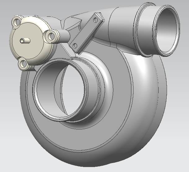
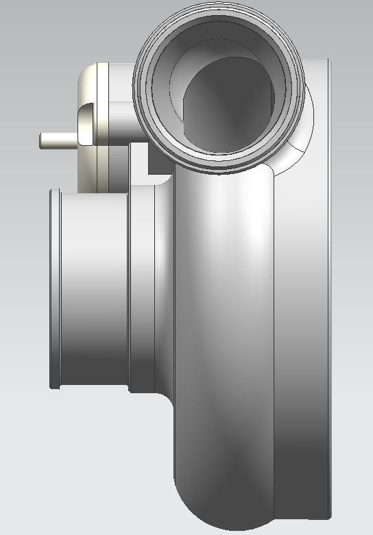
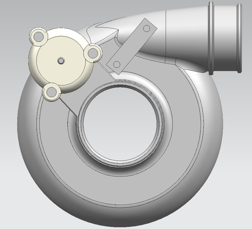
The 3d printer I got is called the form1 by formlabs. It has a smallish build space but builds incredibly detailed parts. When I print the turbo I will just break it into several pieces then assemble it together.
As far as real car work goes, I still need to build the fixture to figure out the perfect turbo placement. Very busy with school and work still, so don't expect and big updates for a while. I'm getting antsy though with a few NC's making big power, can't wait to see what the efr will do on my car.
I spent a good amount of time today building the EFR 6758 in a cad program. I want to do this for two reasons. First is so that I can model it along with the manifold/IC tubing/exhaust in the cad program. Second is so that I can 3d print a plastic mock-up turbo when my 3d printer gets delivered. Yup I ordered a 3d printer, which should allow me to make or prototype a ton of cool car parts really quick.
I got the compressor housing mostly done today with the geometries that are important (BOV housing). I know it isn't perfect but it has all of the necessary geometries to ensure there wont be fitment issues. Next I am going to do a pretty quick chra, a detailed exhaust housing, and the wastegate/bracket. I got all of the measurements using the drafting drawings at the end of the efr turbo tech brief.
turbo cad:


The 3d printer I got is called the form1 by formlabs. It has a smallish build space but builds incredibly detailed parts. When I print the turbo I will just break it into several pieces then assemble it together.
As far as real car work goes, I still need to build the fixture to figure out the perfect turbo placement. Very busy with school and work still, so don't expect and big updates for a while. I'm getting antsy though with a few NC's making big power, can't wait to see what the efr will do on my car.
Reply
1
1
 05-12-2014, 05:39 PM
#25
Senior Member
Thread Starter
iTrader: (6)
Join Date: May 2009
Location: San Francisco
Posts: 983
Total Cats: 23
Well it has been almost a year and still zero progress as far as the turbo NC goes. I did send back the 6758, and am waiting for a v-band inlet/outlet 7163 to replace it 
Hopefully the 7163 will make turbo location a little bit easier in the crowded engine bay. From what I have seen there seems like zero downside to running a 7163 vs 6758.
Don't expect to many updates anytime soon, but expect updates eventually.
Hopefully the 7163 will make turbo location a little bit easier in the crowded engine bay. From what I have seen there seems like zero downside to running a 7163 vs 6758.
Don't expect to many updates anytime soon, but expect updates eventually
.
Reply
0
0
06-19-2014, 07:15 AM
#26
Newb

Join Date: May 2014
Posts: 5
Total Cats: 0
Well it has been almost a year and still zero progress as far as the turbo NC goes. I did send back the 6758, and am waiting for a v-band inlet/outlet 7163 to replace it
Hopefully the 7163 will make turbo location a little bit easier in the crowded engine bay. From what I have seen there seems like zero downside to running a 7163 vs 6758.
Don't expect to many updates anytime soon, but expect updates eventually.
Hopefully the 7163 will make turbo location a little bit easier in the crowded engine bay. From what I have seen there seems like zero downside to running a 7163 vs 6758.
Don't expect to many updates anytime soon, but expect updates eventually
.
Reply
0
0
06-24-2014, 04:53 PM
#28
Newb
Join Date: May 2014
Posts: 5
Total Cats: 0

Reply
0
0

 07-21-2014, 09:23 PM
#31
Senior Member
Thread Starter
iTrader: (6)
Join Date: May 2009
Location: San Francisco
Posts: 983
Total Cats: 23
Real Update!!!
Car is officially off the road, and disassembly has begun in my parents garage. V-band everything 7163 has arrived, and I have finally gotten the bug to start building this setup. In all honestly, I have been so content driving this thing stock with ohlins for the last year, I didn't want to take it off the road. And I was really busy finishing up school.
The Modified Plan
I was never shooting for it to be carb legal, but I was planning on trying to make it pass a sniffer test, and cover up all the turbo stuff with the stock heat shielding etc. so that it looked like stock.
That's not happening anymore.
I started removing pieces from the engine bay to figure out how I am going to route all of the ic and intake plumbing, and I realized how intricate that process was going to be while keeping the stock battery, airbox, and liquid reservoirs in their stock locations.
My new plan of attack is to build everything to be easy to install/remove, and utilize various stock mounting locations for the pieces I need to rearrange. I am going to get this battery to open up some space for the intake:
Braille Battery USA      Lighter • Stronger • Faster -
And I am going to cut a hole similar to the first three pictures seen here on the begi kit for the hot side ic tubing and air intake to fit through. The cold side should fit through the stock hole location for the stock air intake.
BEGI Miata Turbo 2006, 2007, 2008, 2009, 2010, 2011, 2012, 2013 NC MX-5 S3 Turbo
Short term To-do list in rough order of events:
Mount Intercooler
Mount new battery and make new battery tray/holder
Find the perfect turbo location
Make a manifold jig
Make Intercooler end tanks and hot/cold side plumbing
Make Manifold
I am living in San Francisco now, working in Palo Alto 40 miles south, and the car is at my parents another 18 miles south of work, so I am planning on spending at least one night a week working on the car for a few hours. I will be working on the car tomorrow night, so I will make sure to start snapping some pictures.
I may also start a new thread that doesn't have a year of nothingness at the beginning.
Sorry for the hiatus,
Evan
Reply
5
5
08-02-2014, 11:48 PM
#33
Senior Member
Thread Starter
iTrader: (6)
Join Date: May 2009
Location: San Francisco
Posts: 983
Total Cats: 23
I made slight progress over the last couple of weeks, and have a couple of pictures as well.
Here is the turbo
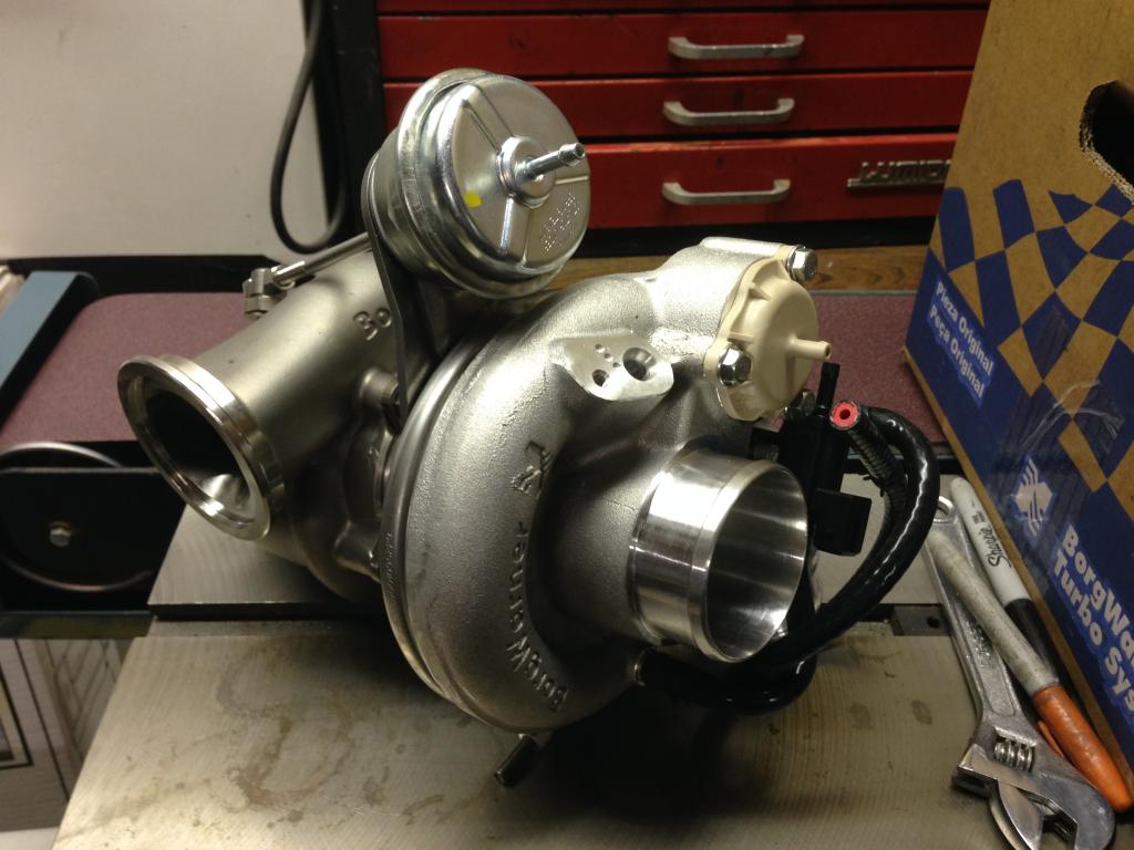
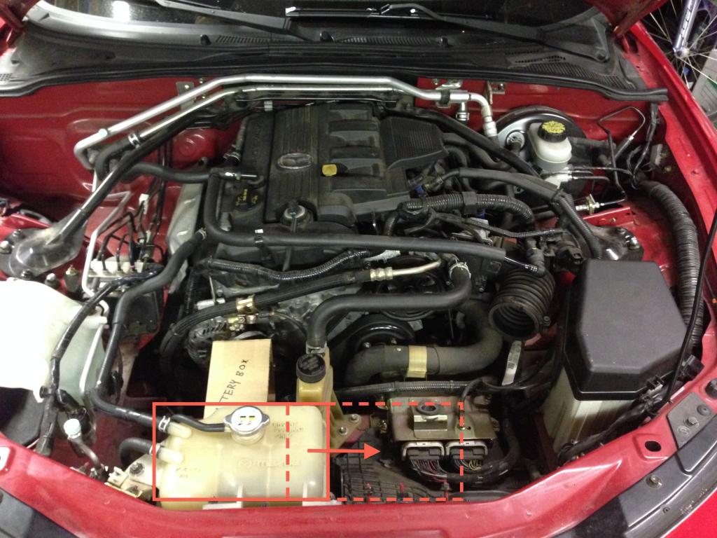
Second picture is of the engine bay as I started to disassemble everything. I ordered a braille battery and designed a new battery box that I am going to build in order to open up some room for the hot side pipes to route to the IC. You can see a cardboard battery mock up in this picture. I actually am going to get the battery that is one size larger than the cardboard mockup. I also am going to move the coolant tank over, as shown by the red boxes and arrows. Luckily, Mazda built in studs at the perfect dimensions to move the reservoir over, I just need to trim away a bit of a plastic tray which inside the dashed red box.
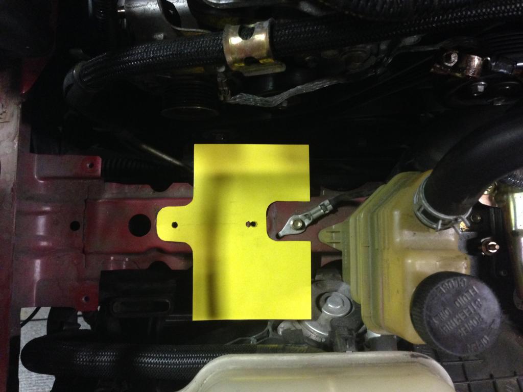
And here is a mockup of where the newly designed battery tray is going to sit. I will post up some images of the battery box design when I am around my cad computer.
I also designed my intercooler mount and got that cad'ed up. I am going to get all of the pieces for the battery box, and the intercooler mount water jet cut to save me some fab time, and I am going to get everything powder coated eventually.
I also have the header removed now, and started trying to place the turbo in its final resting place. It is extremely tight, but there is a sweet spot that everything should line up perfectly. I just need to make a fixture to get the turbo into that sweet spot. I think I am going to have to build a heavy duty adjustable crane to hold the turbo in order to hold it in place to weld the manifold fixture together.
Thats all for now, I may get the turbo placed this week if I am lucky on Tuesday or Wednesday.
Here is the turbo
Second picture is of the engine bay as I started to disassemble everything. I ordered a braille battery and designed a new battery box that I am going to build in order to open up some room for the hot side pipes to route to the IC. You can see a cardboard battery mock up in this picture. I actually am going to get the battery that is one size larger than the cardboard mockup. I also am going to move the coolant tank over, as shown by the red boxes and arrows. Luckily, Mazda built in studs at the perfect dimensions to move the reservoir over, I just need to trim away a bit of a plastic tray which inside the dashed red box.
And here is a mockup of where the newly designed battery tray is going to sit. I will post up some images of the battery box design when I am around my cad computer.
I also designed my intercooler mount and got that cad'ed up. I am going to get all of the pieces for the battery box, and the intercooler mount water jet cut to save me some fab time, and I am going to get everything powder coated eventually.
I also have the header removed now, and started trying to place the turbo in its final resting place. It is extremely tight, but there is a sweet spot that everything should line up perfectly. I just need to make a fixture to get the turbo into that sweet spot. I think I am going to have to build a heavy duty adjustable crane to hold the turbo in order to hold it in place to weld the manifold fixture together.
Thats all for now, I may get the turbo placed this week if I am lucky on Tuesday or Wednesday.
Reply
0
0
08-02-2014, 11:55 PM
#34
Senior Member
Thread Starter
iTrader: (6)
Join Date: May 2009
Location: San Francisco
Posts: 983
Total Cats: 23
Ordered this battery:
Braille Battery USA      Lighter • Stronger • Faster -
Braille Battery USA      Lighter • Stronger • Faster -
Reply
0
0

 08-05-2014, 09:41 PM
#36
Senior Member
Thread Starter
iTrader: (6)
Join Date: May 2009
Location: San Francisco
Posts: 983
Total Cats: 23
Since I don't have that much hands-on time to work on the car, I decided I had to maximize my efficiency while I am able to work on it. That means a new air compressor and new air tools
This is on the way:
Puma PK5020 2-HP 20-Gallon Belt Drive Dual-Voltage Cast-Iron Air Compressor
and so is this this and this:
Plus some impact sockets. Hopefully these make disassembly of **** as fast as I imagine they will.
This is on the way:
Puma PK5020 2-HP 20-Gallon Belt Drive Dual-Voltage Cast-Iron Air Compressor
and so is this this and this:
Plus some impact sockets. Hopefully these make disassembly of **** as fast as I imagine they will.
Reply
0
0
08-25-2014, 11:51 AM
#37
Senior Member
Thread Starter
iTrader: (6)
Join Date: May 2009
Location: San Francisco
Posts: 983
Total Cats: 23
What I consider to be a HUGE UPDATE!
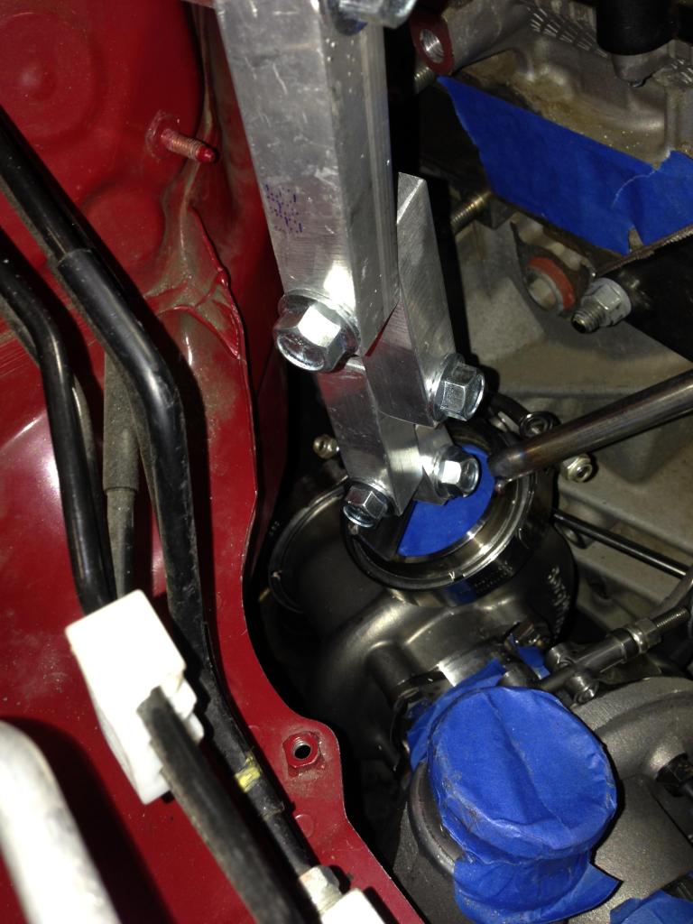
Fitting the EFR into the NC has been a game of inches, and I think I won this battle. I've worked on the car a bit over the last few weeks, and the first thing I did was build an adjustable turbo crane so that I could adjust the turbos location in the engine bay without guess-and-check welding the inlet flange into place. This fixture was monumental in finding the turbos final resting place. It would have been next to impossible to find this exact mounting location without this type of fixture.
Here is the fixture holding the turbo in place (welding was done from the fixture location):
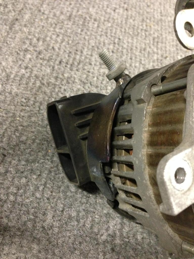
Once I had the fixture in place and holding the turbo, I actually needed to find a workable mounting position. As it turns out, I couldn't locate a place that the turbo would completely fit in the stock engine bay. There was always at least one interference point blocking the turbo from fitting. I decided that the easiest interference point to fix was what I believe to be the ground strap on the back half of the alternator. Someone please tell me if this is more than a ground strap, and if I messed anything up by modifying this piece.
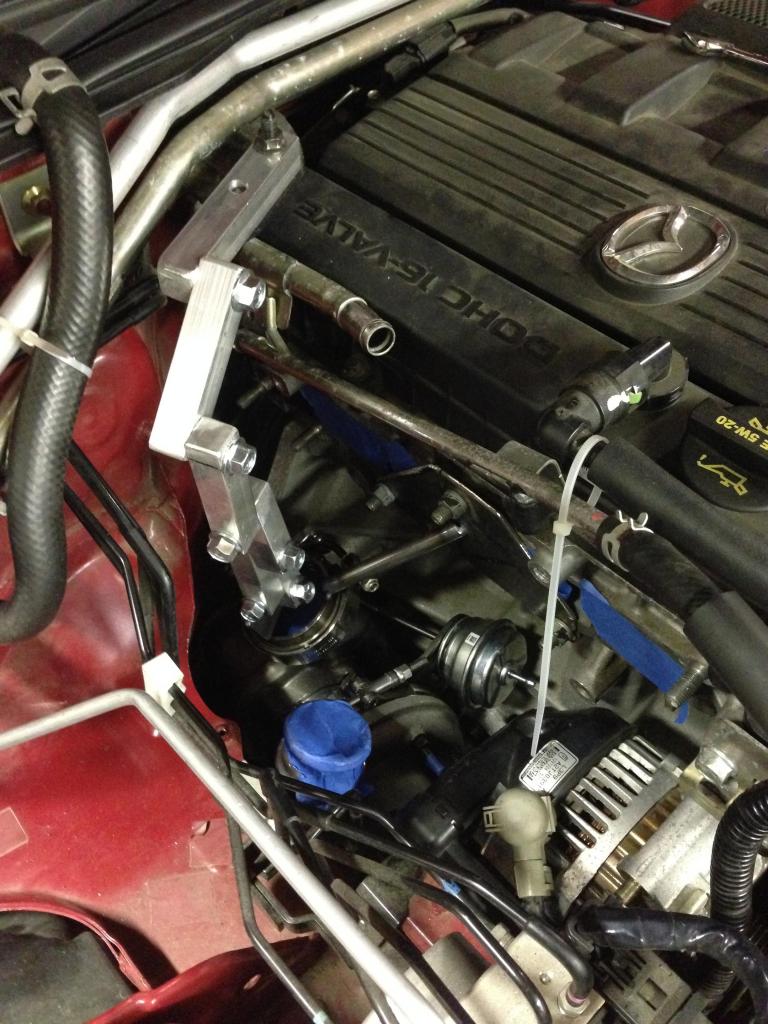
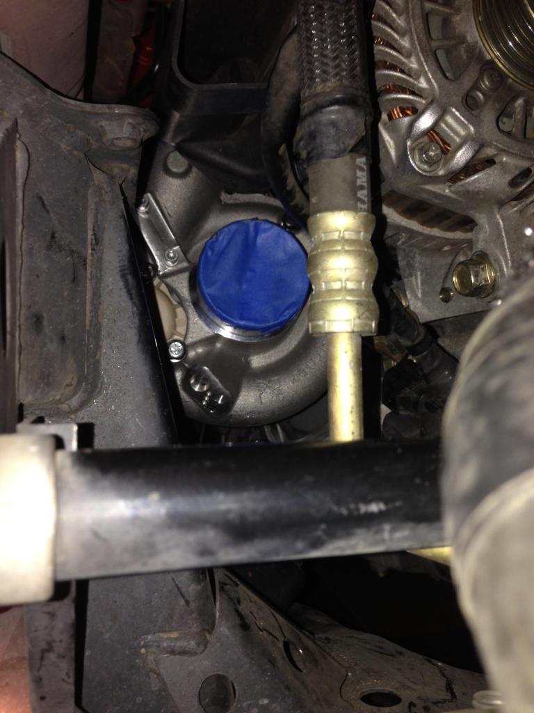
Here is a before picture from the front of the alternator showing the ground strap screw sticking straight out into where the turbo inlet needs to be:
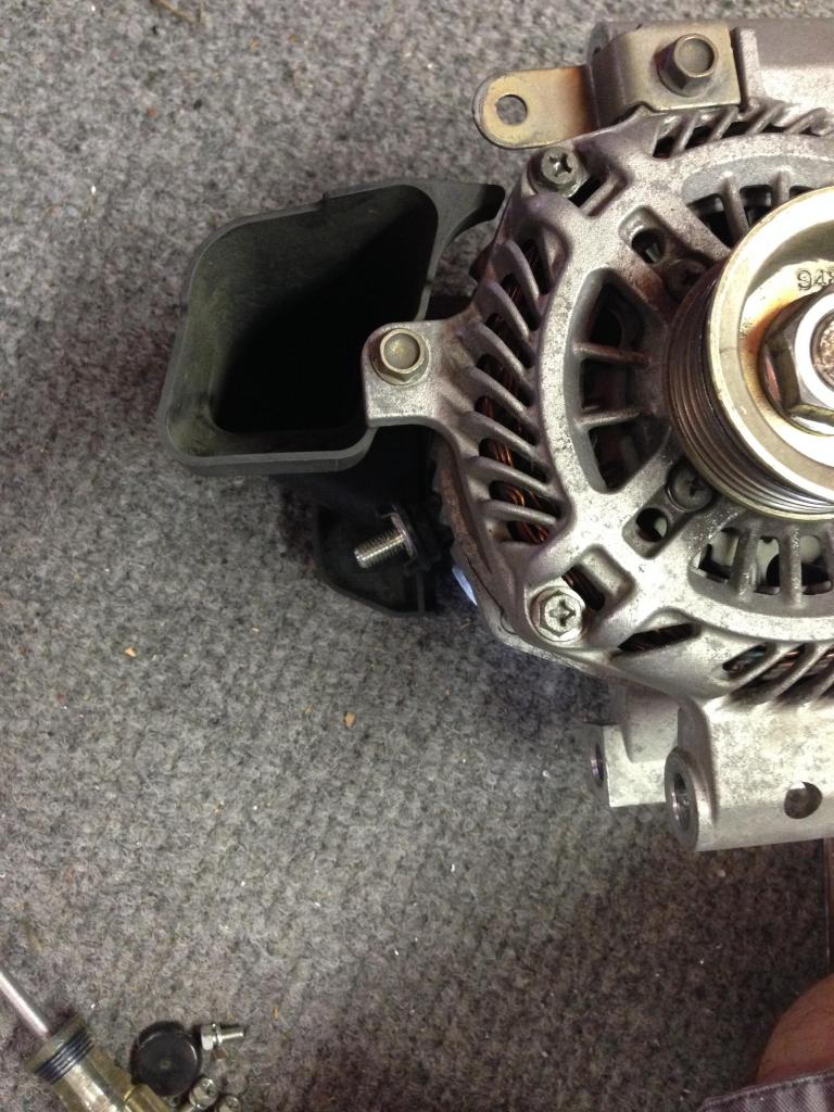
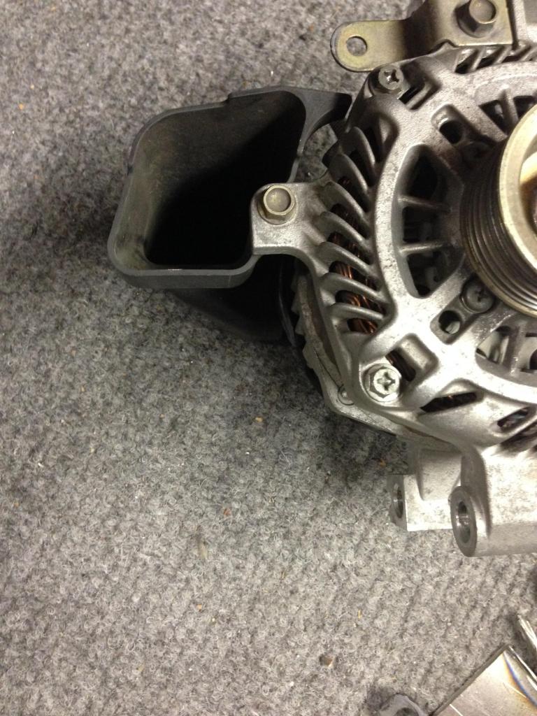
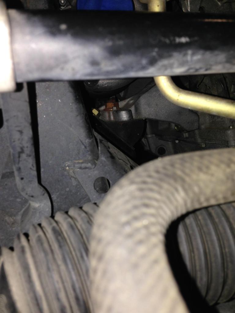
Here is a picture of the modified ground strap bracket I made:
And here is an after picture of where the ground strap bolt used to be:
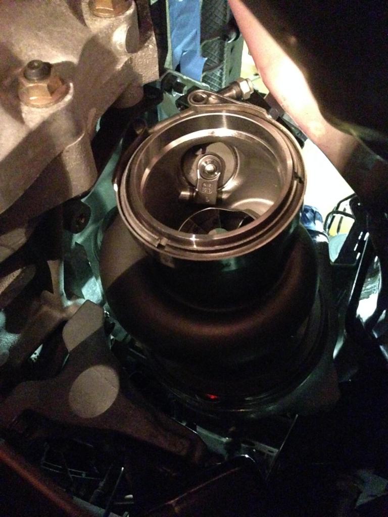
Now that I had "enough" clearance around the turbo, I could lock it down with the fixture, and weld the turbo inlet flange to my mock up head flange piece in order to build my manifold Jig. Here is the final mounted turbo with the welded flange fixture:
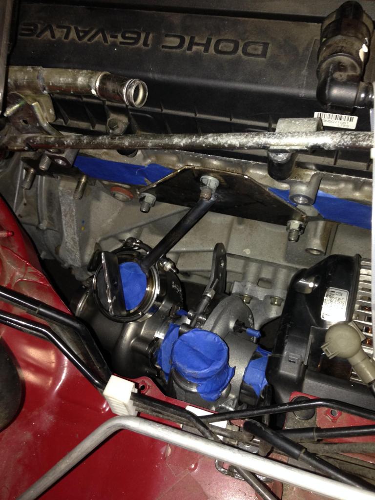
And here are some pictures of how tight the clearance is everywhere. There is around 1/4 inch or less clearance in these places:
comp housing to engine mount bolt
comp housing to a brake line
wastegate canister to engine block
exhaust v band to body
exhaust v band to transmission
turbo inlet to alternator
electronic efr boost controller (might not fit)
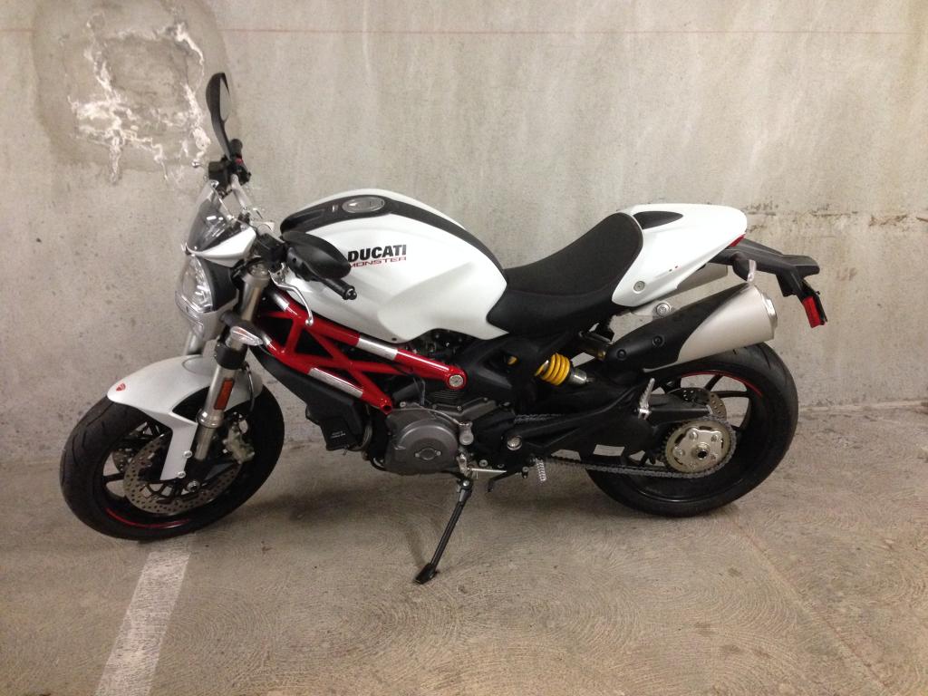
Also, I got a new toy which will be nice for getting back to my garage to get more work done on the car
Fitting the EFR into the NC has been a game of inches, and I think I won this battle. I've worked on the car a bit over the last few weeks, and the first thing I did was build an adjustable turbo crane so that I could adjust the turbos location in the engine bay without guess-and-check welding the inlet flange into place. This fixture was monumental in finding the turbos final resting place. It would have been next to impossible to find this exact mounting location without this type of fixture.
Here is the fixture holding the turbo in place (welding was done from the fixture location):
Once I had the fixture in place and holding the turbo, I actually needed to find a workable mounting position. As it turns out, I couldn't locate a place that the turbo would completely fit in the stock engine bay. There was always at least one interference point blocking the turbo from fitting. I decided that the easiest interference point to fix was what I believe to be the ground strap on the back half of the alternator. Someone please tell me if this is more than a ground strap, and if I messed anything up by modifying this piece.
Here is a before picture from the front of the alternator showing the ground strap screw sticking straight out into where the turbo inlet needs to be:
Here is a picture of the modified ground strap bracket I made:
And here is an after picture of where the ground strap bolt used to be:
Now that I had "enough" clearance around the turbo, I could lock it down with the fixture, and weld the turbo inlet flange to my mock up head flange piece in order to build my manifold Jig. Here is the final mounted turbo with the welded flange fixture:
And here are some pictures of how tight the clearance is everywhere. There is around 1/4 inch or less clearance in these places:
comp housing to engine mount bolt
comp housing to a brake line
wastegate canister to engine block
exhaust v band to body
exhaust v band to transmission
turbo inlet to alternator
electronic efr boost controller (might not fit)
Also, I got a new toy which will be nice for getting back to my garage to get more work done on the car
Reply
0
0
 08-25-2014, 03:15 PM
#40
Senior Member
Thread Starter
iTrader: (6)
Join Date: May 2009
Location: San Francisco
Posts: 983
Total Cats: 23
Before that I can look into moving the brake line, adding an exhaust brace to the trans, and grinding down the motor mount bolt. If those are necessary.
Reply
0
0


