
Stein's 5.0 build thread

Thread Starter
Elite Member
iTrader: (46)
Joined: Dec 2007
Posts: 4,729
Total Cats: 166
From: Nebraska
Right now I'm planning on getting the Miata hubs broached to fit. I want to keep the Miata bolt pattern. T Birds have a 5 on 4.25 pattern which kill wheel choices. The better option is to go to 99? Cobra hubs. Same spline but more friendly wheel choices in 5 on 4.5 pattern.
My other option is to use the T Bird hubs that I will have anyway and redrill for Miata pattern and turn the bearing journal to fit the Miat hubs and bearings. Don't know if that will work or retain the same offset until I have both parts in my hands.
Silicone Boy is pressing out one of his Miata hubs for me to measure both. He has loose Cobra hubs that he is using.
Reply
 0
0

0

Right now I'm planning on getting the Miata hubs broached to fit. I want to keep the Miata bolt pattern. T Birds have a 5 on 4.25 pattern which kill wheel choices. The better option is to go to 99? Cobra hubs. Same spline but more friendly wheel choices in 5 on 4.5 pattern.
My other option is to use the T Bird hubs that I will have anyway and redrill for Miata pattern and turn the bearing journal to fit the Miat hubs and bearings. Don't know if that will work or retain the same offset until I have both parts in my hands.
Silicone Boy is pressing out one of his Miata hubs for me to measure both. He has loose Cobra hubs that he is using.
My other option is to use the T Bird hubs that I will have anyway and redrill for Miata pattern and turn the bearing journal to fit the Miat hubs and bearings. Don't know if that will work or retain the same offset until I have both parts in my hands.
Silicone Boy is pressing out one of his Miata hubs for me to measure both. He has loose Cobra hubs that he is using.
We need pictures when you get the parts in hand.
design sketches
And pictures of girlfriends.
Thanks
Reply
0
0
Thread Starter
Elite Member
iTrader: (46)
Joined: Dec 2007
Posts: 4,729
Total Cats: 166
From: Nebraska
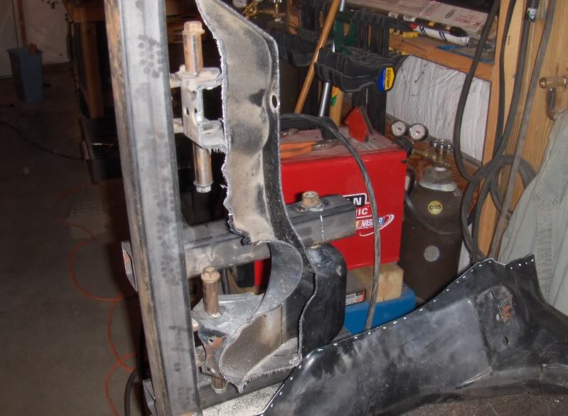
Well, I took the plunge today and cut the subframe.
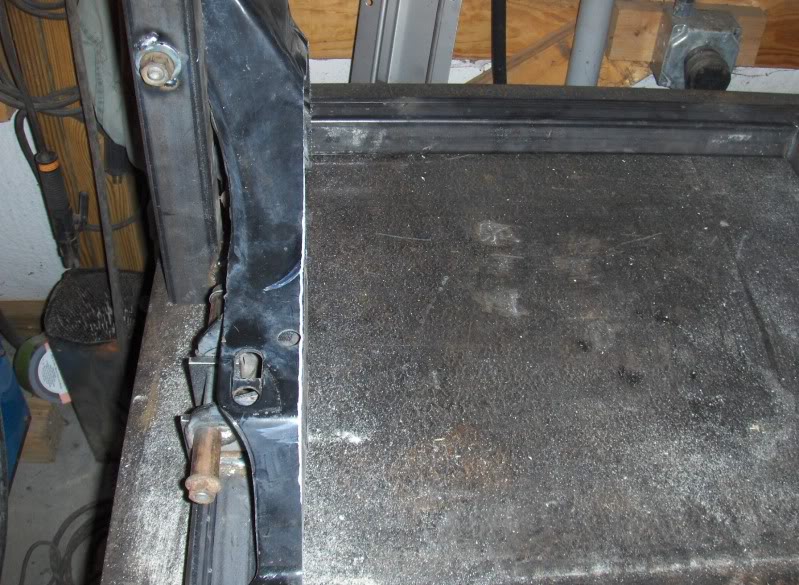
I marked out where I wanted to cut through on the topside for reference. This was only used when I stopped cutting just to see how the sawzall was coming through, as I was cutting the entire subrame at one time from the bottom and some of the cuts were seven inches apart.
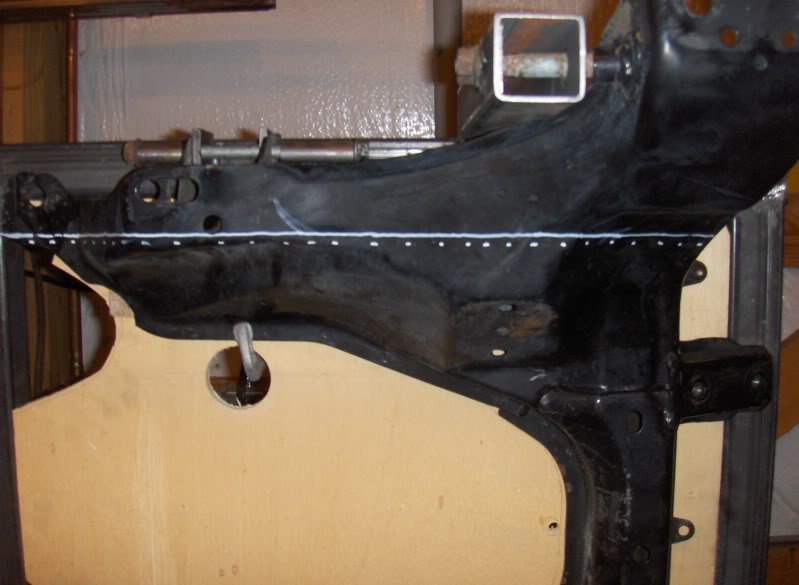
On the back (bottom) I mounted a sacrifical piece of plywood. On that I marked my cut lines. The plywood allowed for a flat surface to guide the shoe of the sawsall, allowed a fine pencil line and helped maintain a perpendicular cut.
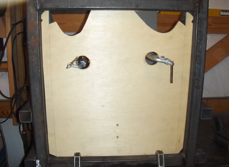
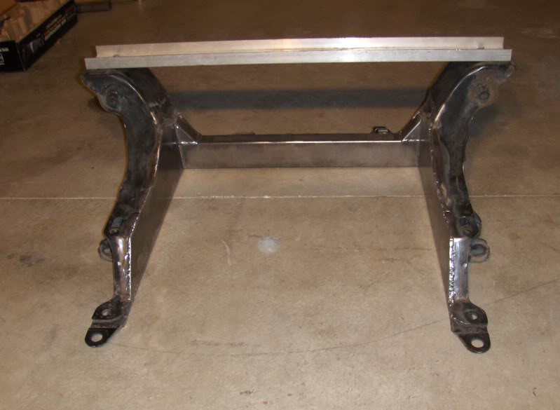
Center section dropped out.
A side view.
I marked out where I wanted to cut through on the topside for reference. This was only used when I stopped cutting just to see how the sawzall was coming through, as I was cutting the entire subrame at one time from the bottom and some of the cuts were seven inches apart.
On the back (bottom) I mounted a sacrifical piece of plywood. On that I marked my cut lines. The plywood allowed for a flat surface to guide the shoe of the sawsall, allowed a fine pencil line and helped maintain a perpendicular cut.
Center section dropped out.
A side view.
Reply
0
0
Thread Starter
Elite Member
iTrader: (46)
Joined: Dec 2007
Posts: 4,729
Total Cats: 166
From: Nebraska
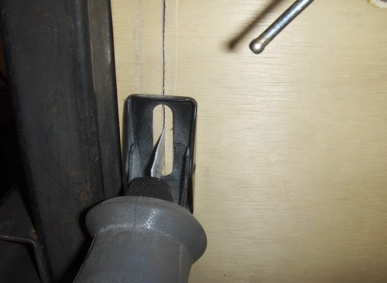
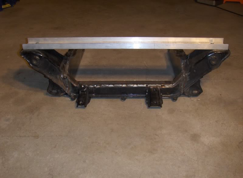
The cut came out very straight. There will be very little cleanup needed to get a perfectly flat place to weld the side plate to.
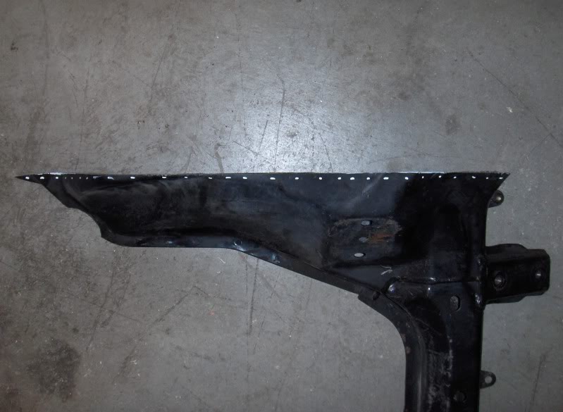
Section that was cut through in one pass. I used one 9" bimetal sawzall blade per side. Cutting through the original motor mount cups was pretty tough going.
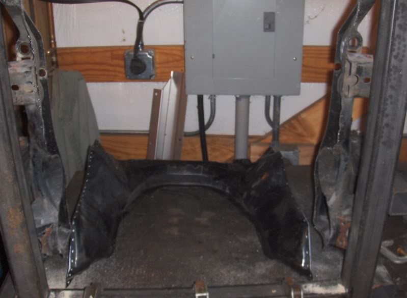
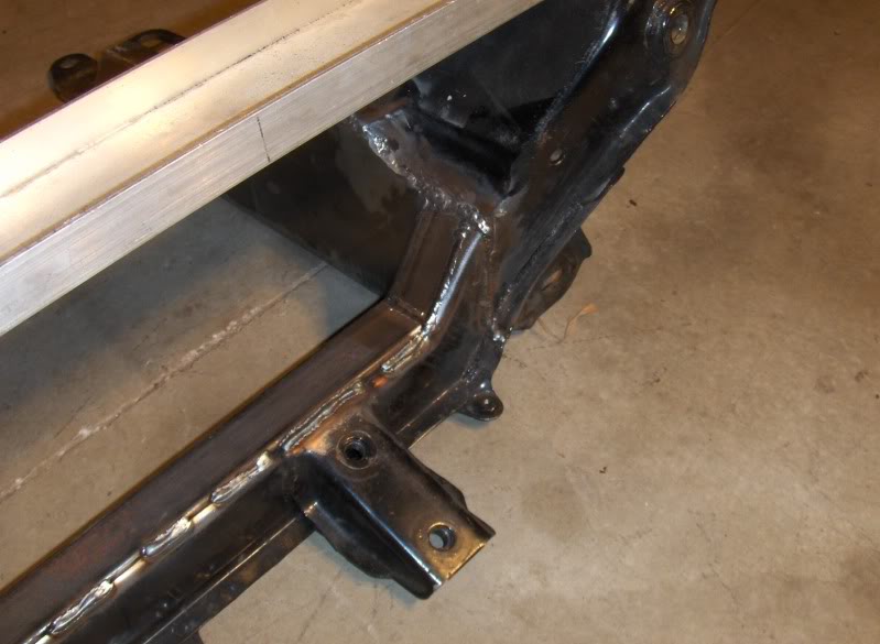
Full on shot looking down the center. There is a little to be cleaned u, but all on the steel safe side. Ten minutes with the angle grinder and I will be good to go.
Right down the line.
All in all, it went very well. After everything was set up, it probably only took 10 minutes to make both cuts.
Next it to cut away the front plate that holds the steering rack brackets. That plate will be welded to the front cross member.
Section that was cut through in one pass. I used one 9" bimetal sawzall blade per side. Cutting through the original motor mount cups was pretty tough going.
Full on shot looking down the center. There is a little to be cleaned u, but all on the steel safe side. Ten minutes with the angle grinder and I will be good to go.
Right down the line.
All in all, it went very well. After everything was set up, it probably only took 10 minutes to make both cuts.
Next it to cut away the front plate that holds the steering rack brackets. That plate will be welded to the front cross member.
Reply
0
0


Great job. What thickness of plate are you going to use?
Reply
0
0
Thread Starter
Elite Member
iTrader: (46)
Joined: Dec 2007
Posts: 4,729
Total Cats: 166
From: Nebraska
Something in the .090"-.125" range. Depends on what I have. .125 is overkill and tougher to cut all of the contours to fit. A bit thicker than what is there now, though. Tubing for the front will be 1 1/2" x 2.75" x .125 wall. Front tubing will be two 1 1/2" x 1 1/2 tubes, cut off one side of one tube and welded together to make a hollow "8" cross section. 3" is a bit too tall from what I have read and the stock subframe is about 2 3/4" thick at that section.
Reply
0
0
Thread Starter
Elite Member
iTrader: (46)
Joined: Dec 2007
Posts: 4,729
Total Cats: 166
From: Nebraska
This just in...
Bought this today.
Mustang Roller 5.0 bored .030 over
TRW forged pistons with Teflon coated skirts
Balanced and polished crank
E-303 Ford Motorsports cam
Cloyes Double Roller Timing Chain
1.6 Adjustable Roller Rockers
Trick Flow Hardened Pushrods
AFR 165 #1402 Heads
Reverse rotation water pump and timing chain cover
Factory front balancer
Mustang double sump oil pan
He also threw in a lightly ported and gasket matched Explorer upper and lower intake after I bought it.
Also, picked up my new $400 hardtop last night!
Last edited by Stein; Nov 11, 2009 at 08:58 AM.
Reply
0
0
Thread Starter
Elite Member
iTrader: (46)
Joined: Dec 2007
Posts: 4,729
Total Cats: 166
From: Nebraska
Welded up my subframe last weekend. Sorry I didn't get any pics yet. I MIG welded it. When I took it out of the frame, some of the bolts were pretty snug but I can get it out and back in so it had to have warped less than 1/16". Easily will be drawn back to normal shape when bolted into the car. Heck, the factory one had almost 1/8" of twist in it before I started.
Anyone want to buy a really nice, heavy duty subframe welding jig? $100 + $50 shipping. It's big and heavy.
Anyone want to buy a really nice, heavy duty subframe welding jig? $100 + $50 shipping. It's big and heavy.
Reply
0
0

This just in...
Bought this today.
Mustang Roller 5.0 bored .030 over
TRW forged pistons with Teflon coated skirts
Balanced and polished crank
E-303 Ford Motorsports cam
Cloyes Double Roller Timing Chain
1.6 Adjustable Roller Rockers
Trick Flow Hardened Pushrods
AFR 165 #1402 Heads
Reverse rotation water pump and timing chain cover
Factory front balancer
Mustang double sump oil pan
He also threw in a lightly ported and gasket matched Explorer upper and lower intake after I bought it.
Also, picked up my new $400 hardtop last night!
Bought this today.
Mustang Roller 5.0 bored .030 over
TRW forged pistons with Teflon coated skirts
Balanced and polished crank
E-303 Ford Motorsports cam
Cloyes Double Roller Timing Chain
1.6 Adjustable Roller Rockers
Trick Flow Hardened Pushrods
AFR 165 #1402 Heads
Reverse rotation water pump and timing chain cover
Factory front balancer
Mustang double sump oil pan
He also threw in a lightly ported and gasket matched Explorer upper and lower intake after I bought it.
Also, picked up my new $400 hardtop last night!
Your project status level has now been upgraded to AweCon1.
PAH!
Reply
0
0

Reply
0
0
Once you get it in there you can start playing the bolt on PAH! game.
This has gone from a good DIY build with a mundane used motor to something unique and definitely worth all that amazing fab work.
No offense to your previous plans...but you know when you get it built everyone will ask what kind of motor etc. etc...and you'll have a lot more fun spitting out that list of specs than just saying "oh, a used tbird motor".
Cheap homebrew has never looked so good.
Reply
0
0
Thread Starter
Elite Member
iTrader: (46)
Joined: Dec 2007
Posts: 4,729
Total Cats: 166
From: Nebraska
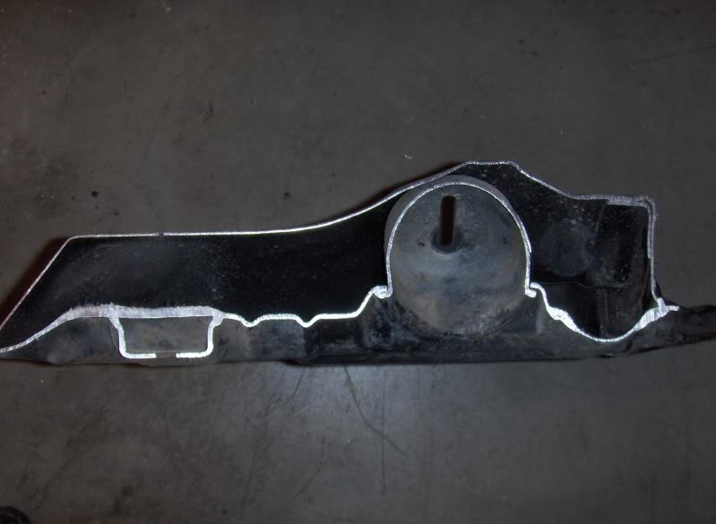
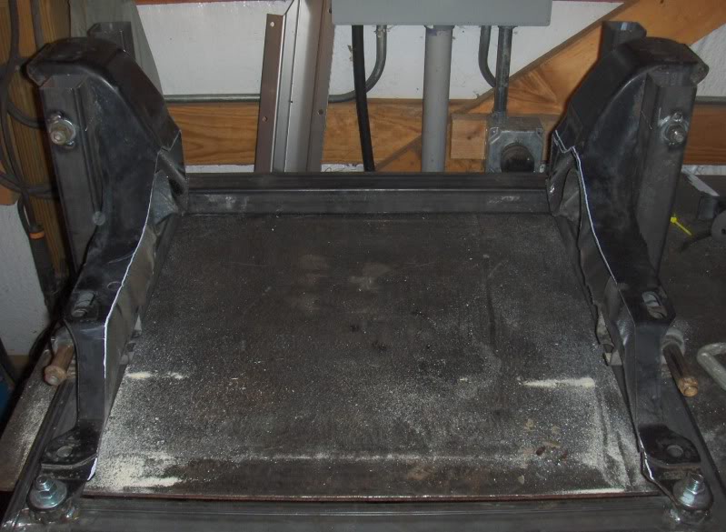
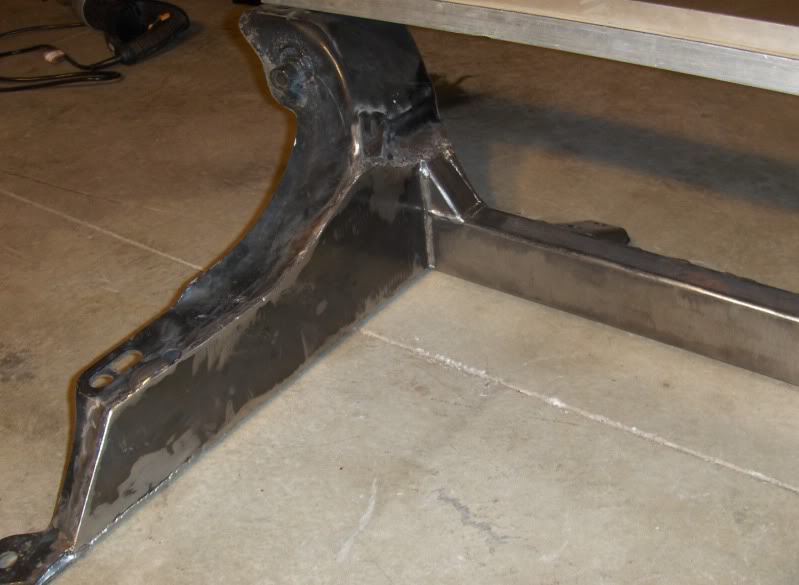
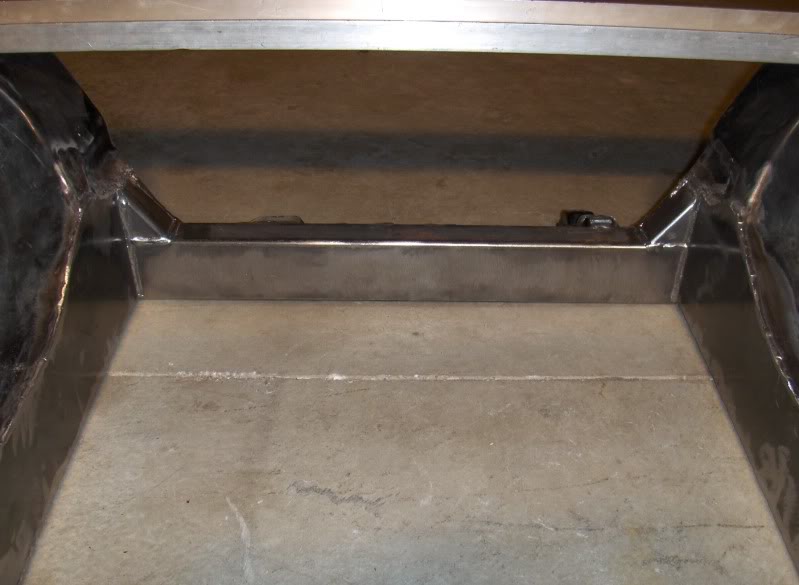
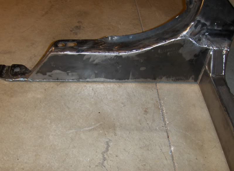
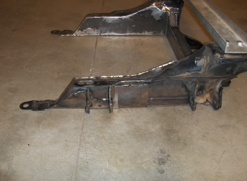
Some pics of the "in process" subframe. I hacked it out to a 21" inside dimension, per CVX_20's domain page. The front cross piece is 2.75" tall x 1.5" wide. I cut 1/4" off of a 1 1/2" square tube the full length and then welded it into an "8" cross section. I trimmed the front plate that carries the steering rack off and welded it to the original subframe and the tubing. A couple short pieces of 1 1/2" tubing coped in to match the angle of the front piece ties in the upright sections. I added .075" sheet to the sides that were cut out and a piece of 1/8x1 1/2" strip to the bottom to box it in. I added one section of plate to the outside to tie in the upper section and the plate on the bottom as well as the rear control arm mount to prevent twisting. I still need to weld some sections like the old cups that housed the motor mount to the side plate.
Reply
0
0


Thread Starter
Elite Member
iTrader: (46)
Joined: Dec 2007
Posts: 4,729
Total Cats: 166
From: Nebraska
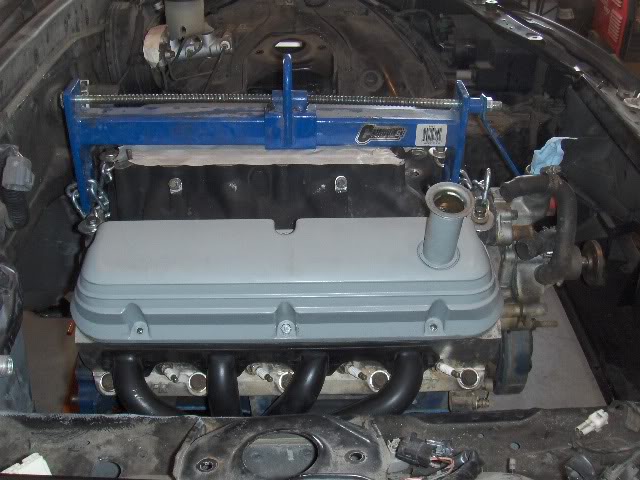
Motor is in, at least as far as the mounting goes. I actually did it twice. The first time I had it all the way back to the power steering cooling loop. It fit well. But then I started looking at the trans and where the shifter fell and it was too far forward. It also looked like the water pump would infringe on the radiator's space.
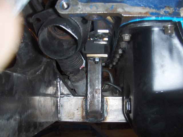
So, I redid the mounts, bent the cooling loop down and was able to move the motor back another 1 1/4". That put the shifter right at the front edge of the hole which seems OK to work with. Sorry, the side view is before I moved it back and I didn't get another shot. Now, the left head is about 1 TO 1 1/2" from the firewall.
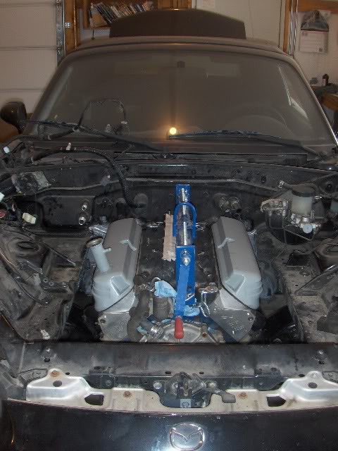
After that I looked at the radiator. I have a 52mm Koyo that I carried over from the turbo car. With the motor moved back, all that I had to do is relocate the lower radiator mounts forward 2" and down 1/2". Basically, I moved the rear bolt hole to the front hole. Did a little trimming so everthing would clear and dropped it in. Slight bend on the stock upper mounting brackets and everything fit perfectly. Need to cut all of the stock Miata fan mounting points off of it yet. There is 1/4" gap from the end of the WP to the radiator. I could cut 1/8" or whatever protrudes through the pulley off of the tip of the pump shaft if I want another bit of clearance.
Headers fit with no problem, other than the notching that I had to do on the passenger side. After moving it back, it was discovered that I wouldn't have had to notch as far forward, thus as tall but everything is boxed and I'm not about to do it again.
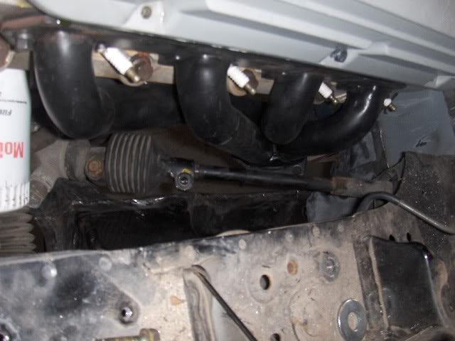
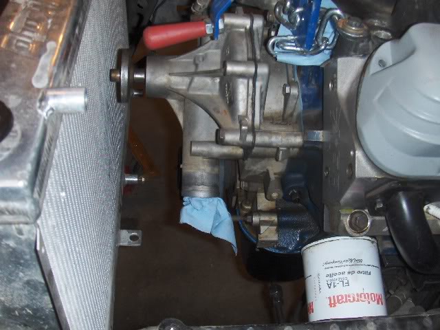
Here's a shot that shows how busy the left mount is. All lines clear by 1/4", plenty of clearance on steering u-joint and collector of header. I have to replace the return line on the PS because it was kinked when The pump hung off of it while installing and dismounting the rack half a dozen times. I have another rack to rob parts off of.
So, I redid the mounts, bent the cooling loop down and was able to move the motor back another 1 1/4". That put the shifter right at the front edge of the hole which seems OK to work with. Sorry, the side view is before I moved it back and I didn't get another shot. Now, the left head is about 1 TO 1 1/2" from the firewall.
After that I looked at the radiator. I have a 52mm Koyo that I carried over from the turbo car. With the motor moved back, all that I had to do is relocate the lower radiator mounts forward 2" and down 1/2". Basically, I moved the rear bolt hole to the front hole. Did a little trimming so everthing would clear and dropped it in. Slight bend on the stock upper mounting brackets and everything fit perfectly. Need to cut all of the stock Miata fan mounting points off of it yet. There is 1/4" gap from the end of the WP to the radiator. I could cut 1/8" or whatever protrudes through the pulley off of the tip of the pump shaft if I want another bit of clearance.
Headers fit with no problem, other than the notching that I had to do on the passenger side. After moving it back, it was discovered that I wouldn't have had to notch as far forward, thus as tall but everything is boxed and I'm not about to do it again.
Here's a shot that shows how busy the left mount is. All lines clear by 1/4", plenty of clearance on steering u-joint and collector of header. I have to replace the return line on the PS because it was kinked when The pump hung off of it while installing and dismounting the rack half a dozen times. I have another rack to rob parts off of.
Reply
0
0

Not sure if u mentioned this but what is your engine management/ wiring plans. I am in the middle of a custom megasquirt setup on a supercharged 5.0 using the TFI setup.
Reply
0
0


