
Yet Another Trackspeed S1/ST4 Build Thread


Thread Starter
Joined: Nov 2006
Posts: 15,442
Total Cats: 2,106
From: Sunnyvale, CA
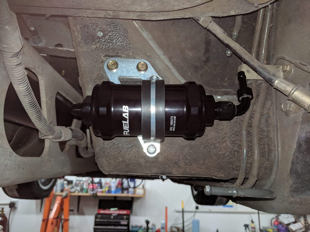
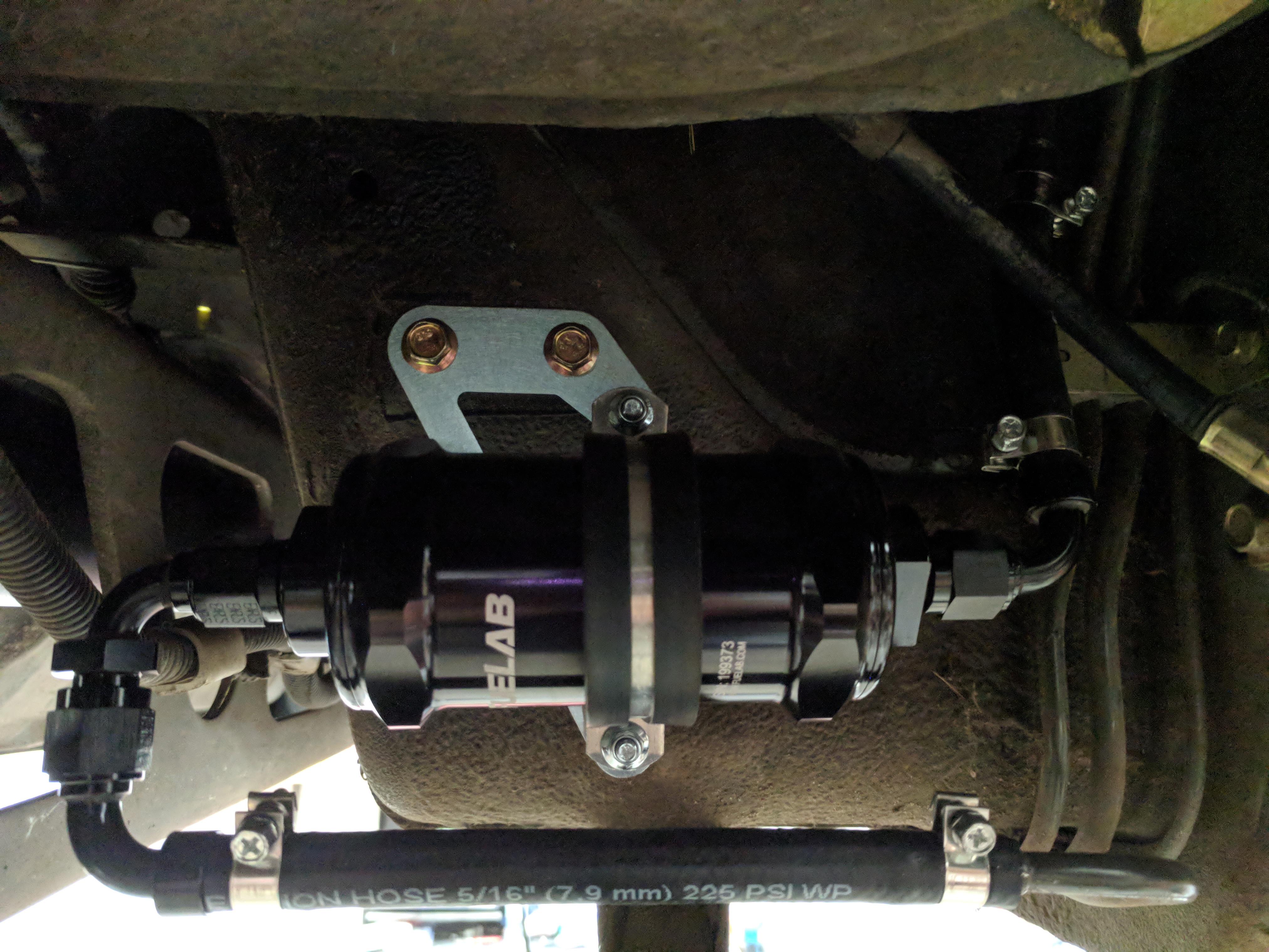
PnP adapter bracket for a Fuelab 818 in the stock location. These will be on the site shortly along with fittings and hose for a fully E85-compliant plug-and-play fuel filter solution.
f anyone has an NB and wants to try one, I'll send one free in exchange for you telling me whether it fits or not and snapping a few photos if it does.
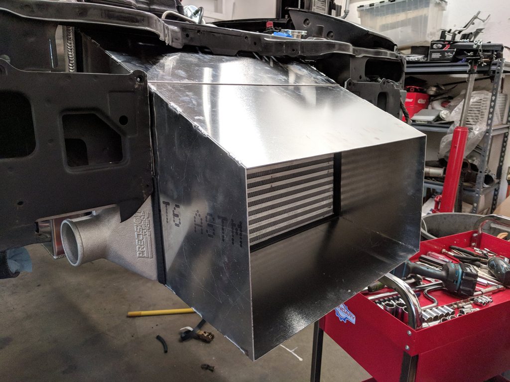
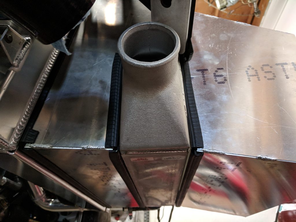
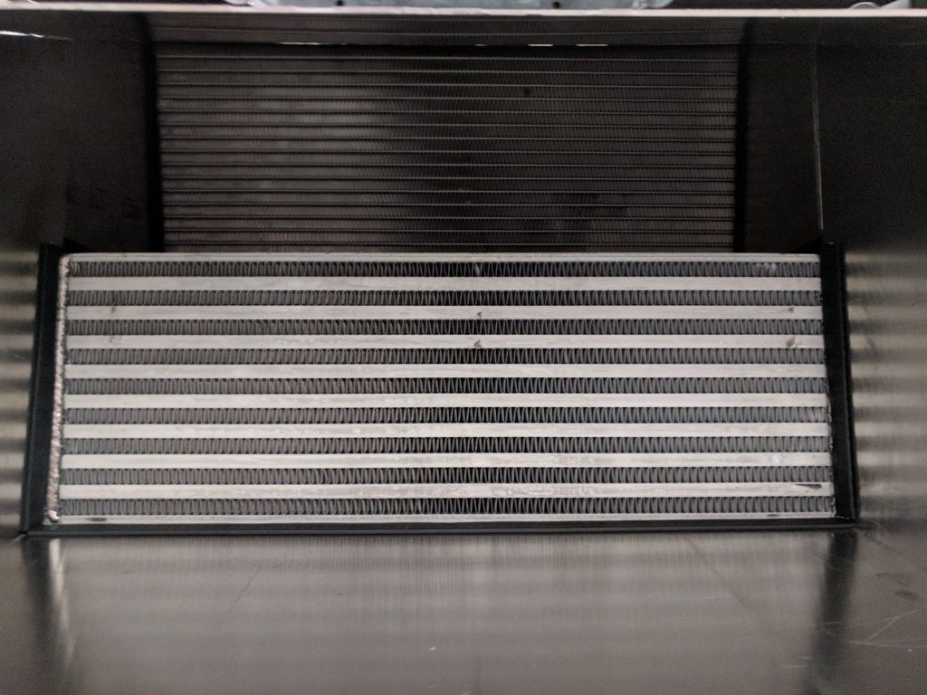
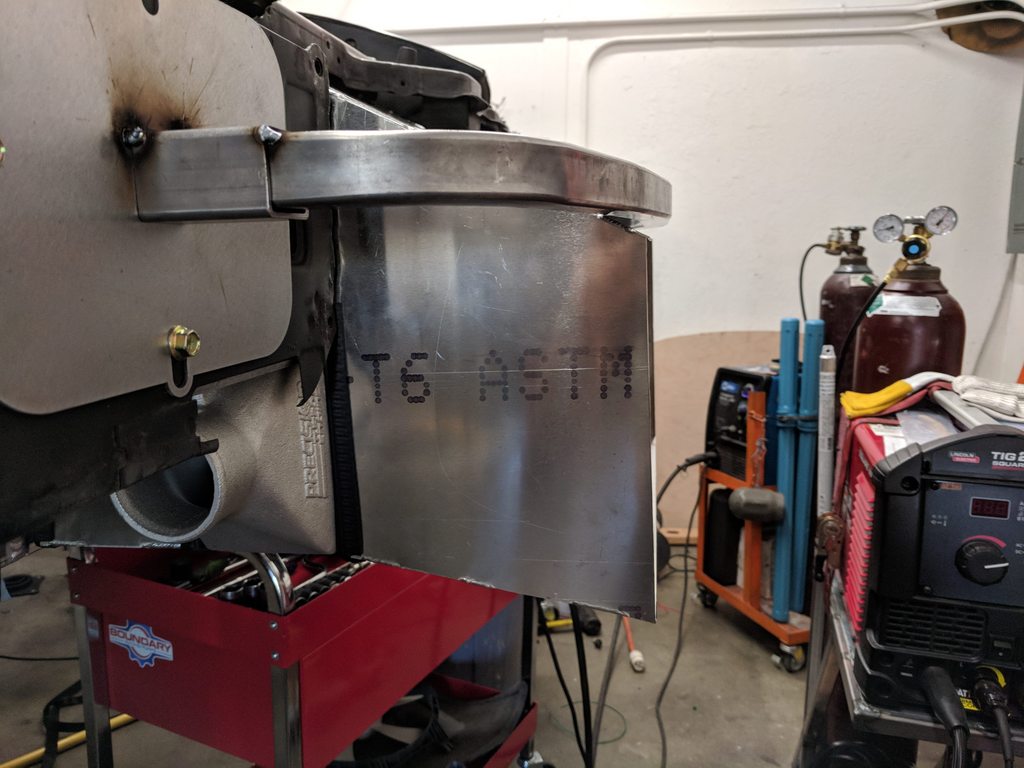
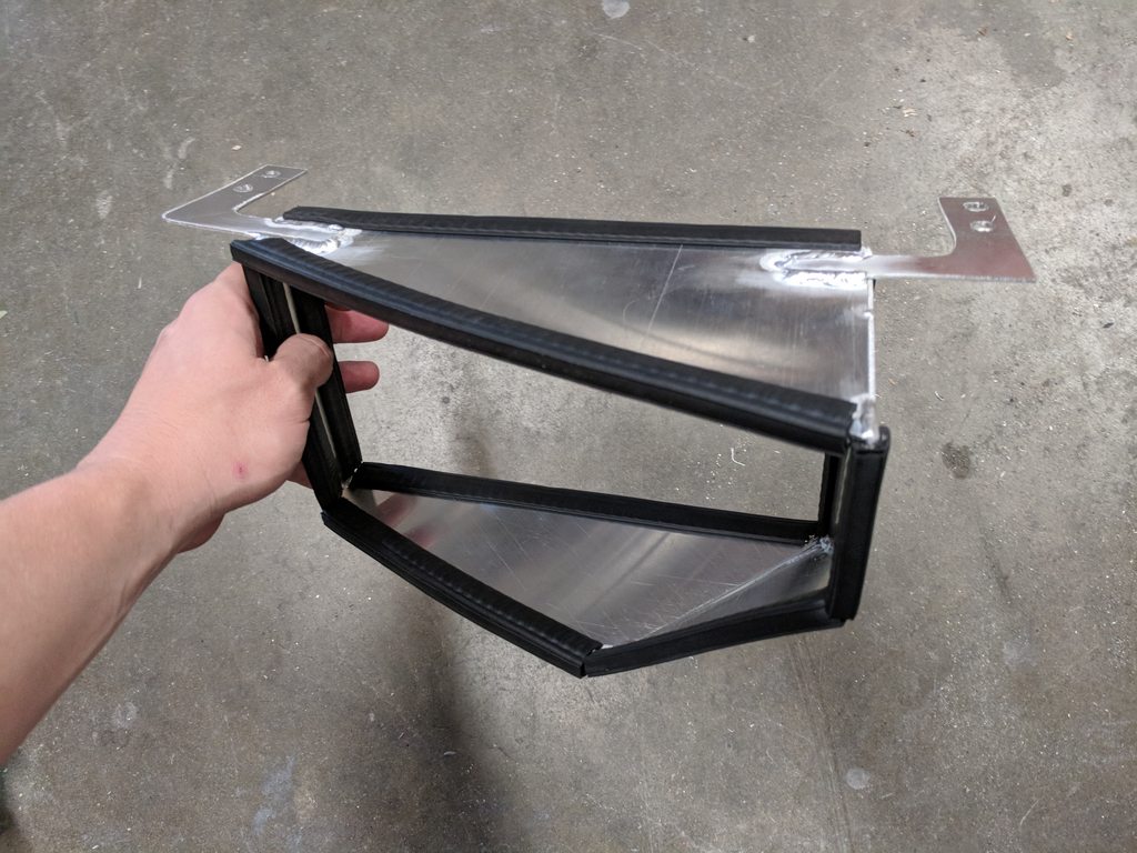
Knocked this out this week. Pretty happy with how it turned out. Started with a few basic measurements, then put everything into CAD, then CAD templates to .060" sheet aluminum. Oil-resistant rubber seals against the heat exchangers so everything seals up nice. The ducting is held in place by the heat exchangers and front bumper, so there's a better chance of everything surviving if it gets bumped during a race. I also revised the bumper beam to bring it right out to the bumper skin.
f anyone has an NB and wants to try one, I'll send one free in exchange for you telling me whether it fits or not and snapping a few photos if it does.
- Radiator and intercooler install, IC piping, cutting up the front end, and adding all the requisite ducting.
Reply
 2
2

2
All-round "Good Guy"

Joined: Dec 2009
Posts: 1,036
Total Cats: 266
From: Brisbane, AUSTRALIA
At one time I had a BEGi front air scoop (it extends below the intercooler and ducts fresh air upwards) which decreased the effectiveness of the intercooler since it turned the area between the radiator and intercooler into a high pressure area which meant less fresh air flowed through the intercooler, making it less effective.
Are you concerned about this at all?
ie. Should you add a "shelf" that extends from a ledge in front of the intercooler to the radiator to ensure that the air flows through the intercooler without being affected by the additional backpressure or is there enough air flow through the radiator for this not to be an issue?
Reply
0
0


I have an NB sitting in my garage which could be your test mule if you wish. Let me know. It won't be moving any time soon. Well, unless the garage rebuild contractors have an opening sooner than I think they do.
Reply
0
0


Thread Starter
Joined: Nov 2006
Posts: 15,442
Total Cats: 2,106
From: Sunnyvale, CA
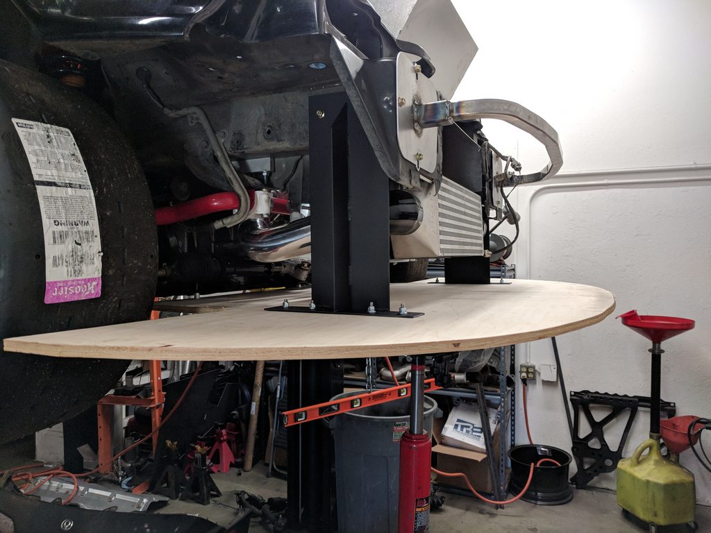
Splitter and splitter brackets going on this week. Decided to do something a little different than I've done in the past. I usually drop a section of 1" steel square tube off the front bumper supports, but they are a bit flimsy and off-track incidents can bend them up. I wanted to try something stronger, and this is definitely that.
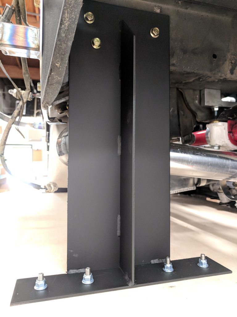
The brackets turned out good, although a bit overkill. I did them in 1/8" steel and they really would be totally fine in 1/8" aluminum. If there's demand I will do a small run in aluminum.
The wood is 1/2" ply as usual, all the screws are countersunk and they are the weakpoint. An off-track excursion would rip the bolts through the bottom of the wood if need be.
Also got the first prototype for our fuel pump rewire kits in. Super nice. In Acamas, I passed 10awg TXL through the top of the hangar via studs. It worked, but the install was extremely messy and really not for the faint of heart (drilling holes in your gas tank and all). In researching the factory connector and pins a bit further, I discovered the terminals themselves in the factory connector are rated to 25A, but the housing and seals are too small to take a 10AWG wire.
Enter M22759/32. Milspec wire means we can get the same current through a smaller gauge of wire, and the thin insulation further reduces the size, enough to make the factory connector and seals viable. Add a nice relay, fuseholder, ring terminals, and proper lengths to put the relay where it needs to go, and it becomes the obvious choice.
The most elegant solutions are often the simplest, and that's definitely true here.
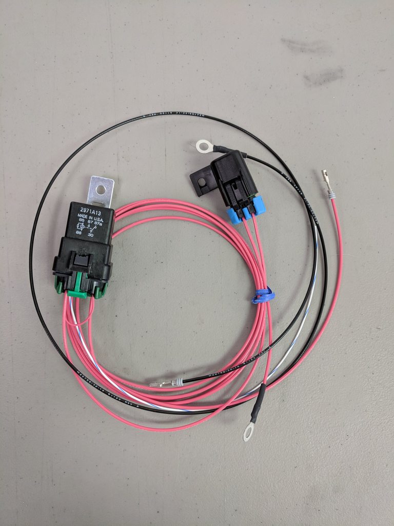
With this harness, the install becomes a breeze. You just unwrap the factory wiring and gromet, depin the old connector, pass the new harness through the gromet, and pin up the new (provided) connector with the new power/ground wires and the old fuel level sender wires. The ground for the fuel pump goes to the factory ground location (driver's side seatbelt tower), and the power wire runs through a 35A relay and 25A fuse to either the battery (street application) or master cutoff switch (race application). All the pins are pre-crimped, so the only wiring connection you have to make is between the old power wire (repurposed as a trigger) and the new relay trigger wire. Bypass the OEM relay with a short jumper wire and you're done.
A few folks have had issues with main relays, and big aftermarket fuel pumps are the reason. All of the current for the fuel pump passes through the main relay first, and it is by far the largest amp draw through that relay. Go from a factory pump that might pull 5 amps on a good day to a Walbro 400-E85 that pulls 19 amps at 100psi outlet pressure, and you're going to cause issues in the wiring/electrical system. This kit alleviates that load, shifting it off the main relay and onto a dedicated 35A relay drawing power straight off the battery.
This will become a standard install item for me when I build a car. The moment I touch the fuel pump, it will get rewired as well. Too easy, too inexpensive not to do.
Trackspeed Fuel Pump Rewire Kit
The brackets turned out good, although a bit overkill. I did them in 1/8" steel and they really would be totally fine in 1/8" aluminum. If there's demand I will do a small run in aluminum.
The wood is 1/2" ply as usual, all the screws are countersunk and they are the weakpoint. An off-track excursion would rip the bolts through the bottom of the wood if need be.
Also got the first prototype for our fuel pump rewire kits in. Super nice. In Acamas, I passed 10awg TXL through the top of the hangar via studs. It worked, but the install was extremely messy and really not for the faint of heart (drilling holes in your gas tank and all). In researching the factory connector and pins a bit further, I discovered the terminals themselves in the factory connector are rated to 25A, but the housing and seals are too small to take a 10AWG wire.
Enter M22759/32. Milspec wire means we can get the same current through a smaller gauge of wire, and the thin insulation further reduces the size, enough to make the factory connector and seals viable. Add a nice relay, fuseholder, ring terminals, and proper lengths to put the relay where it needs to go, and it becomes the obvious choice.
The most elegant solutions are often the simplest, and that's definitely true here.
With this harness, the install becomes a breeze. You just unwrap the factory wiring and gromet, depin the old connector, pass the new harness through the gromet, and pin up the new (provided) connector with the new power/ground wires and the old fuel level sender wires. The ground for the fuel pump goes to the factory ground location (driver's side seatbelt tower), and the power wire runs through a 35A relay and 25A fuse to either the battery (street application) or master cutoff switch (race application). All the pins are pre-crimped, so the only wiring connection you have to make is between the old power wire (repurposed as a trigger) and the new relay trigger wire. Bypass the OEM relay with a short jumper wire and you're done.
A few folks have had issues with main relays, and big aftermarket fuel pumps are the reason. All of the current for the fuel pump passes through the main relay first, and it is by far the largest amp draw through that relay. Go from a factory pump that might pull 5 amps on a good day to a Walbro 400-E85 that pulls 19 amps at 100psi outlet pressure, and you're going to cause issues in the wiring/electrical system. This kit alleviates that load, shifting it off the main relay and onto a dedicated 35A relay drawing power straight off the battery.
This will become a standard install item for me when I build a car. The moment I touch the fuel pump, it will get rewired as well. Too easy, too inexpensive not to do.
Trackspeed Fuel Pump Rewire Kit
Last edited by Savington; Jun 1, 2018 at 11:29 PM.
Reply
2
2
Beautiful work Andrew. If I hadn't already bought the bulkhead connectors I would be buying your rewire kit. Where do you find is the best place to mount the relay, and do you run the wires to the battery or to the alternator?
Reply
0
0
Thread Starter
Joined: Nov 2006
Posts: 15,442
Total Cats: 2,106
From: Sunnyvale, CA
I'm going to tuck the relay right behind the passenger seat under the bulkhead cover. Power will run to the cutoff switch on this car, but on Acamas it's run to the battery.
Reply
0
0
Thread Starter
Joined: Nov 2006
Posts: 15,442
Total Cats: 2,106
From: Sunnyvale, CA
Have not seen. Several companies make a Civic splitter bracket which inspired the design on these, but none that I saw had the stiffening rib added. With the rib running all the way up to the bolt holes, those brackets are very stout. They would be stout in AL, too, and they'd weigh a lot less.
Reply
0
0
Joined: Apr 2014
Posts: 18,643
Total Cats: 1,870
From: Beaverton, USA
Have not seen. Several companies make a Civic splitter bracket which inspired the design on these, but none that I saw had the stiffening rib added. With the rib running all the way up to the bolt holes, those brackets are very stout. They would be stout in AL, too, and they'd weigh a lot less.

Reply
0
0

Elite Member
Joined: Jul 2014
Posts: 1,641
Total Cats: 250
From: Canberra, sort of
Do you really need four bolts there? Assuming some rear attachment (which I think I can see in one of those photos) would two bolts suffice? That would reduce the mangling of the mounting plate if/when the two outer bolts pull through. I know that is fixable with the traditional BFH, but still.
I used a similar mount, my sacrificial link was a piece of light aluminium angle between the upright and the wooden splitter, strong enough for me to stand on the lip and bounce. I never put it to the test on impact though, so whether it would have worked as intended I never found out. I do like the idea of countersinking the screws as the weak point, I never though of that.
I used a similar mount, my sacrificial link was a piece of light aluminium angle between the upright and the wooden splitter, strong enough for me to stand on the lip and bounce. I never put it to the test on impact though, so whether it would have worked as intended I never found out. I do like the idea of countersinking the screws as the weak point, I never though of that.
Reply
0
0
Thread Starter
Joined: Nov 2006
Posts: 15,442
Total Cats: 2,106
From: Sunnyvale, CA
Two would probably work. It draws the "fuse" point of the bolts down a bit. I want the splitter to hold on through some off-roading, but tear off before the brackets twist or bend (likely twist based on design). There are two more points at the rear edge of the spliiter which bolt into the tabs on the subframe which normally retain the factory undertray, so 10 bolts in all.
The countersinking weakens the wood in the important spots, but it's mostly there so the bolt heads don't get scraped off on curbs, the track, etc. Learned my lesson on that one.
The countersinking weakens the wood in the important spots, but it's mostly there so the bolt heads don't get scraped off on curbs, the track, etc. Learned my lesson on that one.
Reply
0
0

This will become a standard install item for me when I build a car. The moment I touch the fuel pump, it will get rewired as well. Too easy, too inexpensive not to do.
Trackspeed Fuel Pump Rewire Kit
Trackspeed Fuel Pump Rewire Kit
Reply
0
0
Thread Starter
Joined: Nov 2006
Posts: 15,442
Total Cats: 2,106
From: Sunnyvale, CA
Took some time off this summer to expand our facility but I am back on this project. Trying to push to have it running and maybe on-display at MRLS.
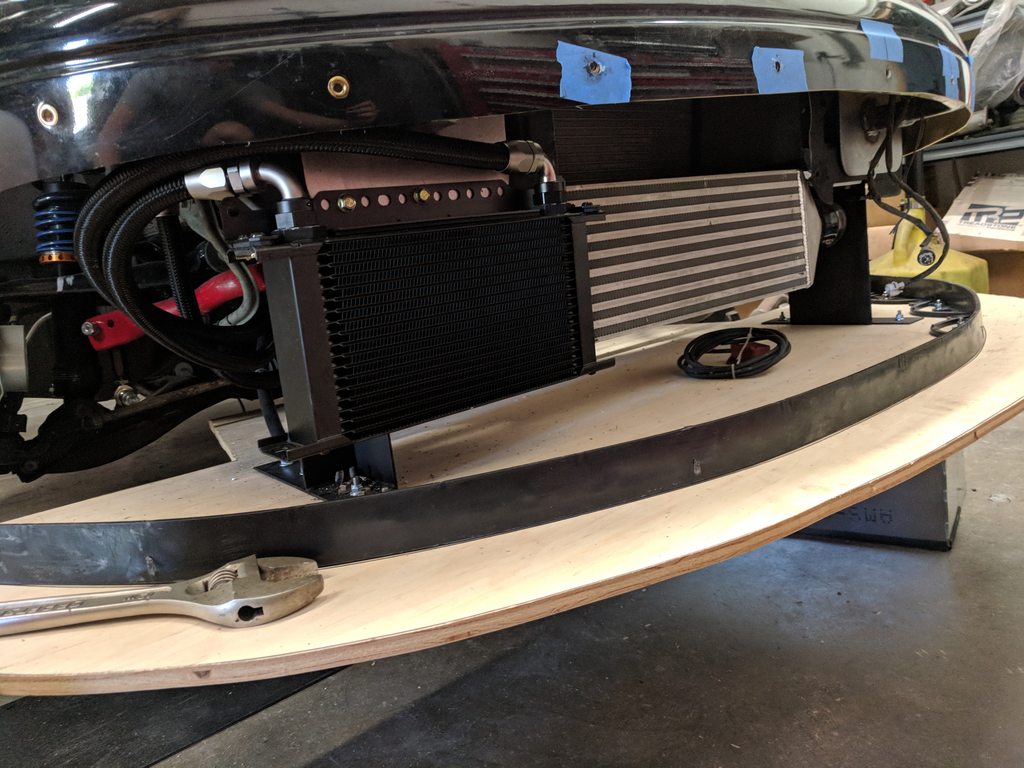
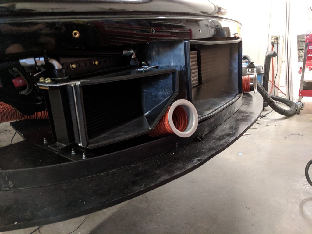
One of the things I was trying to sort out when I took off in June was the oil cooler location. I have gone behind the IC on the last couple of cars I've done and while it's convenient, it's not the "right" place. I am much happier with this. The 3" ducts complicate things a bit, but this is as close to ideal as I can think of for now. There will be a couple of holes in the air dam to feed air to that duct, a 4" and a 3". Aesthetically, that will be more pleasing than just a big gaping hole, and it should allow plenty of airflow into the ducted box.
Also fleshed out the ducting, added a support rib for the airdam, painted the splitter, etc. Front end is just about done. Waiting for a soft tow strap for the front end and it will get buttoned up for good.
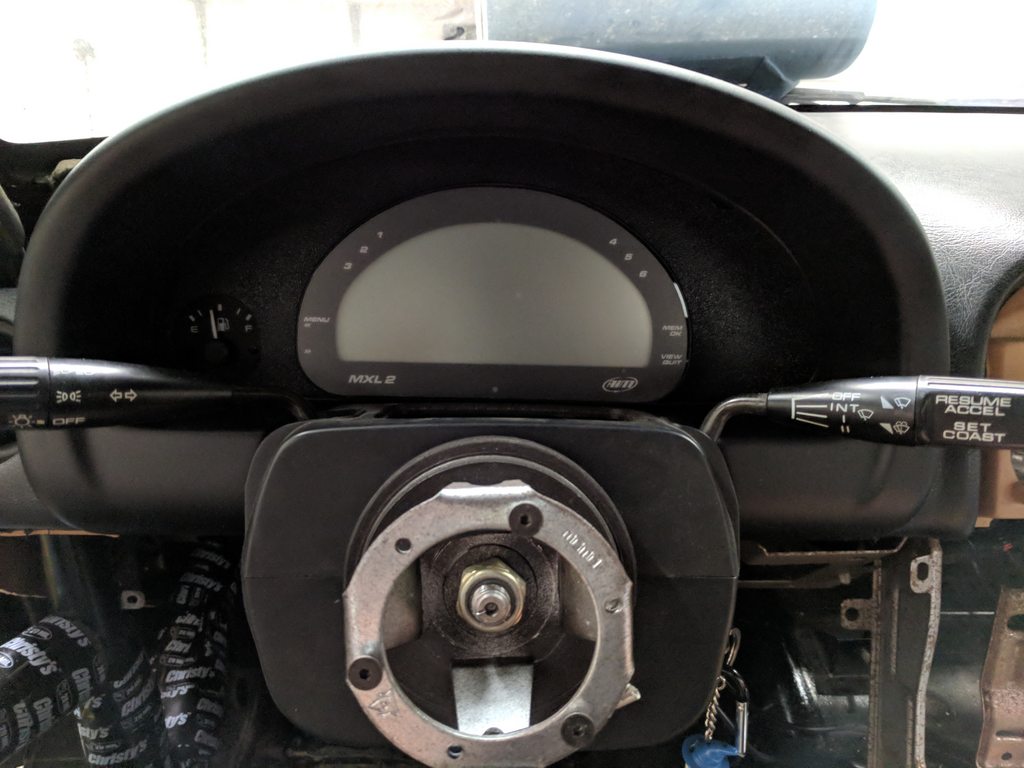
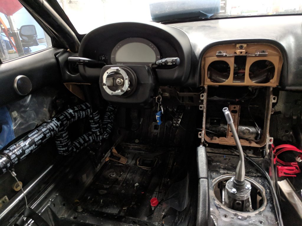
AIM MXL2 and stock fuel gauge in the interior. I have tried every manner of hooking up a fuel level reading on the AIM and it never ends up working quite as well as the OEM gauge. Going to copy this for Rover at some point. MR shifter is also in. Need to fab up a blockoff plate for the center console and the interior will be done from my end. Tony at TC will add two new FIA seats, fresh belts, and a SPA AFFF-AR fire system.
Fuelab 818 all plumbed up and ready to roll. These do fit NAs and NBs, I have a full plumbed-in solution that will be on the site shortly for NAs. Still sorting out the NBs, those fuel injection fittings add some difficulty to things.
Pressing towards start-up at the end of the week.
One of the things I was trying to sort out when I took off in June was the oil cooler location. I have gone behind the IC on the last couple of cars I've done and while it's convenient, it's not the "right" place. I am much happier with this. The 3" ducts complicate things a bit, but this is as close to ideal as I can think of for now. There will be a couple of holes in the air dam to feed air to that duct, a 4" and a 3". Aesthetically, that will be more pleasing than just a big gaping hole, and it should allow plenty of airflow into the ducted box.
Also fleshed out the ducting, added a support rib for the airdam, painted the splitter, etc. Front end is just about done. Waiting for a soft tow strap for the front end and it will get buttoned up for good.
AIM MXL2 and stock fuel gauge in the interior. I have tried every manner of hooking up a fuel level reading on the AIM and it never ends up working quite as well as the OEM gauge. Going to copy this for Rover at some point. MR shifter is also in. Need to fab up a blockoff plate for the center console and the interior will be done from my end. Tony at TC will add two new FIA seats, fresh belts, and a SPA AFFF-AR fire system.
Fuelab 818 all plumbed up and ready to roll. These do fit NAs and NBs, I have a full plumbed-in solution that will be on the site shortly for NAs. Still sorting out the NBs, those fuel injection fittings add some difficulty to things.
Pressing towards start-up at the end of the week.
Last edited by Savington; Mar 12, 2019 at 05:41 PM.
Reply
6
6
Have you tried the Iron Canyon unit? We have that with our stock tank/sender/MXL2, and it reads about like stock. 100% for a while, tapers smoothly to 0%, and we can run on 0% for ~5-10 minutes. This all takes ~1:50 with 185hp. We had to do a custom sensor calibration like any fuel cell sending unit.
Reply
0
0


