
COP Thread


Well, I'm interested in this and I'm gonna head out to my local junkyard here in a minute, but could someone explain how these would get wired into a STOCK 1.6 ecu?
I've read this whole thread about twice now, but I'm not a whiz at engine electronics so I still don't really understand where/what I'm cutting/splicing into. Any help would be greatly appreciated!
-Sean
I've read this whole thread about twice now, but I'm not a whiz at engine electronics so I still don't really understand where/what I'm cutting/splicing into. Any help would be greatly appreciated!
-Sean
Last edited by honeydesean; Jul 1, 2007 at 01:52 PM.
Reply
 0
0

0

I'm fairly sure the sport bike coils don't have an integrated igniter. You could still trigger a set of VB921s mounted in a project box and use the vb921 outputs to trigger the coils. Basically make you own external igniter box.
Reply
0
0
Well, I'm interested in this and I'm gonna head out to my local junkyard here in a minute, but could someone explain how these would get wired into a STOCK 1.6 ecu?
I've read this whole thread about twice now, but I'm not a whiz at engine electronics so I still don't really understand where/what I'm cutting/splicing into. Any help would be greatly appreciated!
-Sean
I've read this whole thread about twice now, but I'm not a whiz at engine electronics so I still don't really understand where/what I'm cutting/splicing into. Any help would be greatly appreciated!
-Sean
If you don't have a basic understanding of how an ignition system works or how coils are fired and understand the four stroke internal combustion engine and it's general workings not to mention a good understanding of electricity then you probably shouldn't try.
The Mazda ignition wiring, at the coil, consists of two coils each firing 2 cylinders each. There are 2 connectors at each coil. It has been explained what the wires are for and what there colors mean. I've explained there are two triggers (the wire that contains the pulse from the ecu that tells the coil's internal ignitor to fire the coil) and those triggers fire two cylinders together. Also you'll find 12v-power, Ground, and another wire that is the tach output from the coil to the tach. The ignition system's firing order is 1&4(coil 1)-2&3(coil 2). Not 1-3-4-2. This is called wasted spark because one of the sparkplugs is being fired on the top of the exhaust stroke and doesn't ignite anything. That's why it's called "wasted" because it doesn't fire on a power stroke. The cop coils will have to be connected to do the same. I don't have time right now but I'll draw up a schematic soon.
Reply
0
0
To use the Toyota coils you will need nothing but the coils, wire snips, solder and an iron (recomended), heatshrink tubing, and electrical tape. The coils sort of hold themselfs in place but if you want to bolt them down you need some 1/2" round aluminum rod about 1/2" long and drill and tap it for a 6mm bolt. Then JB weld the threaded spacers you just made to the valve cover after cleaning it thoroughly. One of the coils will use a valve cover bolt hole but you'll need a spacer or a few washers and a longer bolt. It just happens to line up with it. I've been really busy lately but I did plan a write-up if I can get to it. If anyone else wants to snap a few pics of there progress I'm sure it would help.
Reply
0
0
Ok a VB921ZV is the component number. It's a TO-220 package coil driver. Internally it looks like an NPN transistor with built in drive and current limiting circuitry. Hmm... Handy little bugger. I wonder how well it would work for PWM motor control.
http://www.chipcatalog.com/Datasheet...EB5174903D.htm
Well I would have posted the PDF but the forum limit of 45k will not allow me to. Has anyone ever seen a PDF as small as 45k? Philip where are you? Can this be changed to 300k? ...any PDF longer then one sentence is bigger then 45k. We all know Adobe bloat.
Reply
0
0
This is going to complicate things for the 1.6L. If the 1.6L coils do not have the drivers built in then I'll need the schematics for it. You can still wire it up but you'll have to intercept the trigger from the ecu before it gets to the 1.6L ignitor if it has one.
Reply
0
0
Yea, I think that may be where I'm getting stuck with your directions.
This is what I'm looking at for my coil pack(luckly I've just got a spare chillin)
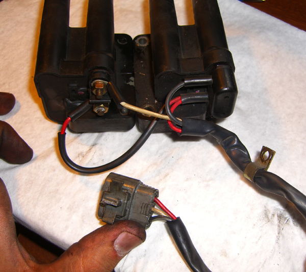
Note how the red wire connects to both.
This is what I'm looking at for my coil pack(luckly I've just got a spare chillin)
Note how the red wire connects to both.
Reply
0
0

Junior Member
Joined: Nov 2006
Posts: 254
Total Cats: 0
From: Santa Clarita, CA
i thought the ingitor was in the ecu, cause you have to solder one in on MS if you wanted to squirt a 1.6, if it was bolted to the firewall, there would be no need to solder one in. right? but again i'm speaking out of my ***
Reply
0
0
Following the wires it comes to this, which according to the wiring diagram for a 92 is the igniter.
Here you see the labels.
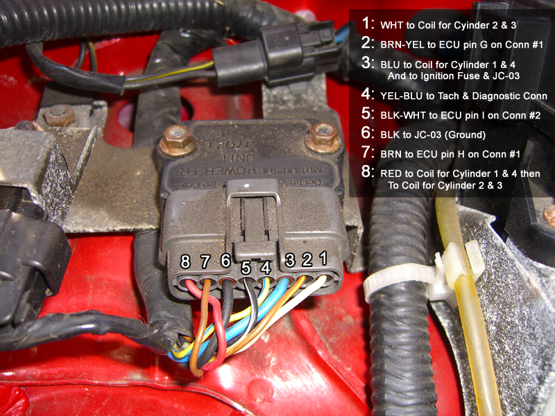
And here is the back of the plug so you can see the wires.
Here you see the labels.
And here is the back of the plug so you can see the wires.
Last edited by honeydesean; Jul 1, 2007 at 10:36 PM.
Reply
0
0


