
Correct Outlet Flange sizing

Thread Starter

Joined: Jan 2013
Posts: 5,031
Total Cats: 861
From: Seneca, SC
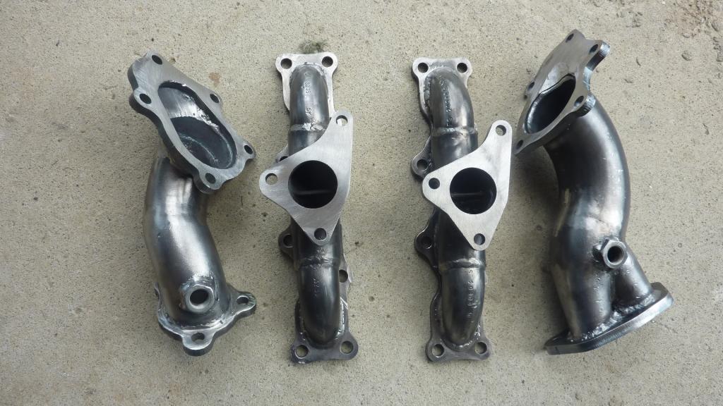
Here is a TD04 outlet flange (downtube flange): Turbo Outlet Flange Subaru EJ20 EJ25 WRX STI Dump Down Pipe | eBay
Is the fact that it is smaller all around, including at the bolting locations, non-ideal? Or does this not matter. I have access to tools to machine my own to whatever dimensions I wish, but for $18, I might forgo that flange. However, if it will not work as well, I will make my own.
Is the fact that it is smaller all around, including at the bolting locations, non-ideal? Or does this not matter. I have access to tools to machine my own to whatever dimensions I wish, but for $18, I might forgo that flange. However, if it will not work as well, I will make my own.
Reply
 0
0

0


Senior Member
Joined: Apr 2011
Posts: 507
Total Cats: 75
From: Martin, Slovakia
That flange is strange.
Divided downpipes on Subarus don't make much sense as usually there is no separation of the wastegate flow within the turbo?
Also the wastegate flap only opens by around 12mm (actuator max travel) and will never be at right angles like shown in the picture.
The wastegate directs the flow towards the turbo outlet. Bell-mouths are sometimes used but a single 3" with a lead in should also work well.
EDIT: David I understand, you all ready have a divided downpipe that you will connect to. That fange with a divider plate could work.
I have drawings for these flanges if you need

Last edited by sturovo; Sep 7, 2013 at 03:52 PM.
Reply
0
0
Long time ago i watched a vid explaining the separated downpipes. Some turbos are not separated so they add a separator. The reason for it is when the wastegate opens all the flow goes towards the main outlet and smacks the flow at a 90ish degrees. So use a separator to block the wastegate flow from directly going into the flow of the main outlet.
Actually here we go, found it.
Actually here we go, found it.
Reply
0
0
Thread Starter
Joined: Jan 2013
Posts: 5,031
Total Cats: 861
From: Seneca, SC
18PSI: Thanks.
Sturovo: I have used your drawings, but I can only get the hole locations from them to transfer to Pro-E, and I have been building the outlines by making 1:1 plots, comparing to the actual turbine flanges and iterating the shapes. Working pretty well.
Sturovo & triple88a: I plan to use a piece of 2" tube to create a baffle on the turbine side of the plate that will, along with the walls of the turbine outlet, act as if the 2" downpipe is an extension of the outlet port. This will create a turbine outlet port almost identical to a housing used in an external waste gate. Then the wastegate area will be fully separate and will flow into the separated pipe.
Reply
0
0
Senior Member
Joined: Apr 2011
Posts: 507
Total Cats: 75
From: Martin, Slovakia
Long time ago i watched a vid explaining the separated downpipes. Some turbos are not separated so they add a separator. The reason for it is when the wastegate opens all the flow goes towards the main outlet and smacks the flow at a 90ish degrees. So use a separator to block the wastegate flow from directly going into the flow of the main outlet.
In the description of the video it states
Brett reveals one of MRTs biggest secrets, the split dump pipe. He shows how this can reduce lag by 300 rpm and adds power.
The description of "90 deg followed by another 90 deg" gas flow is not an accurate representation of what is going on. There is some overlap between the open wastegate and downpipe csa.

The flow path is inclined at around 45 deg and directed towards the chamber wall. This is probably a design feature that Mitsubishi engineers came up with to generate swirl and promote effective mixing of the wastegate and turbo flows.

I am not convinced that adding a dividing plate to a bell mouth is such a good idea. The wastegate flow has to bounce around and change direction before being reintroduced a few inches further downstream.

I guess the benefit adding a dividing plate is even more questionable for a divorced waste gate downpipe as in the case of the posted ebay flange . The port will be significantly blocked by the wastegate flap when it is open? It may well be better to allow the wastegate gasses to flow towards the turbo outlet.
Reply
0
0
Thread Starter
Joined: Jan 2013
Posts: 5,031
Total Cats: 861
From: Seneca, SC
Sturovo, my thoughts, perhaps misguided, are more about increasing the efficiency of the turbine outlet than the wastegate. By a shaped dividing plate, I hope to smooth that flow. Since it seems that the boost drops with RPM on the dyno's I've seen with the TD04 wastegate performance does not seem to be the drawback. I may be attributing to the turbine what is really a deficiency with the compressor. A quote of a quote from Jay Kavanaugh of Garrett, "As for the geometry of the exhaust at the turbine discharge, the most optimal configuration would be a gradual increase in diameter from the turbine's exducer to the desired exhaust diameter-- via a straight conical diffuser of 7-12" included angle (to minimize flow separation and skin friction losses) mounted right at the turbine discharge..". That is my goal.
Reply
0
0

Senior Member
Joined: Apr 2011
Posts: 507
Total Cats: 75
From: Martin, Slovakia
my thoughtsare more about increasing the efficiency of the turbine outlet than the wastegate. By a shaped dividing plate, I hope to smooth that flow. "As for the geometry of the exhaust at the turbine discharge, the most optimal configuration would be a gradual increase in diameter from the turbine's exducer to the desired exhaust diameter-- via a straight conical diffuser of 7-12" included angle (to minimize flow separation and skin friction losses) mounted right at the turbine discharge..". That is my goal.
Why not go a step further than just a section of 2" pipe? It should be possible to fit a 3" to 2.25" reducer in there.


I all ready want to try

Reply
0
0
Thread Starter
Joined: Jan 2013
Posts: 5,031
Total Cats: 861
From: Seneca, SC
Sweet. That is exactly the effect I'm looking for. My DP is not 3", but the principle is wonderful. Really create the transition with minimum leakage. The outside of the small end can of the transition can be ground to eliminate any step.
Reply
0
0
Interesting sales/promotional video. Not sure I understand a few of the points raised though.
In the description of the video it states
Reducing lag means that boost builds faster? The wastegate is usually shut until target boost is reached so a split dump pipe would not improve lag if the split part is not being used?
In the description of the video it states
Reducing lag means that boost builds faster? The wastegate is usually shut until target boost is reached so a split dump pipe would not improve lag if the split part is not being used?
Reply
0
0
Senior Member
Joined: Apr 2011
Posts: 507
Total Cats: 75
From: Martin, Slovakia
Reply
0
0

Thread
Thread Starter
Forum
Replies
Last Post
Zaphod
MEGAsquirt
47
Oct 26, 2018 11:00 PM
StratoBlue1109
Miata parts for sale/trade
21
Sep 30, 2018 01:09 PM


