When you click on links to various merchants on this site and make a purchase, this can result in this site earning a commission. Affiliate programs and affiliations include, but are not limited to, the eBay Partner Network.
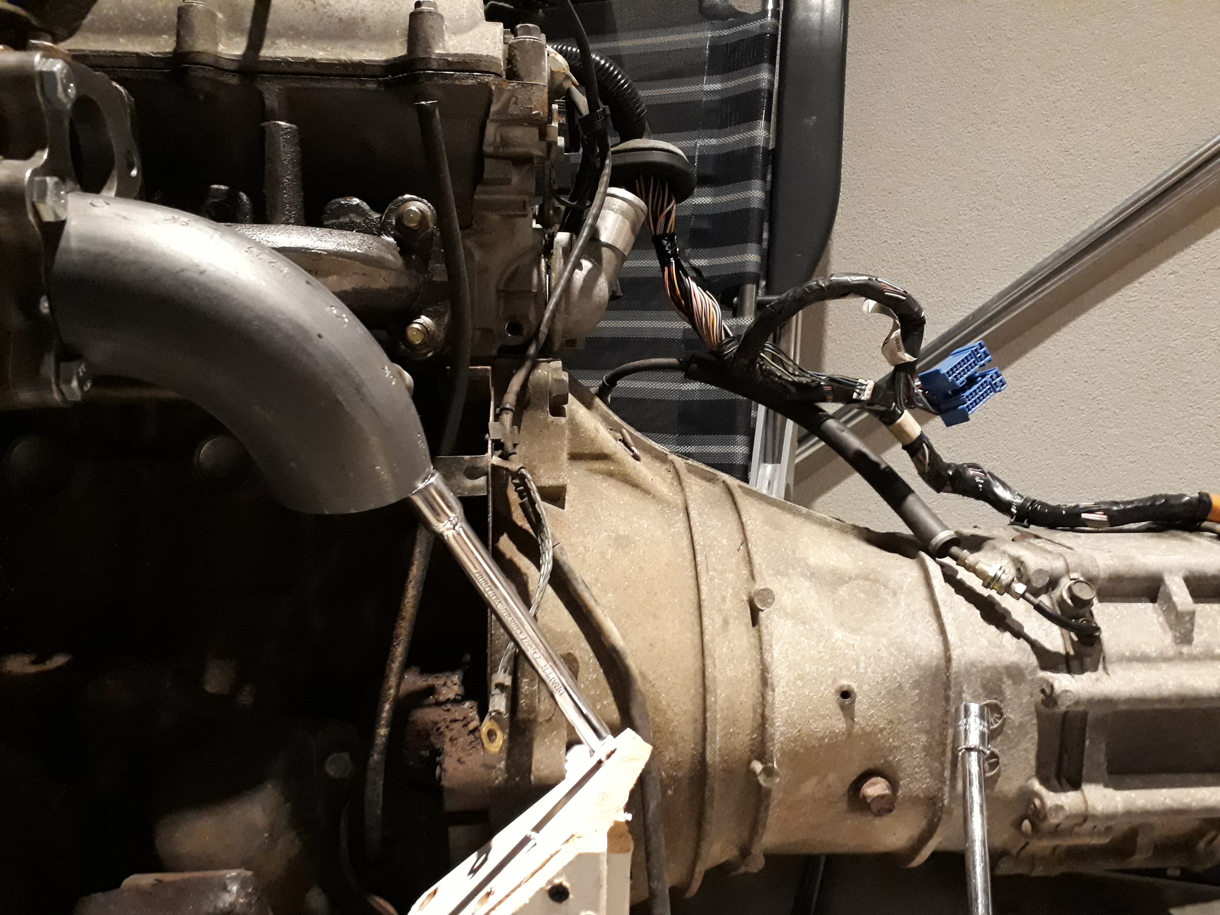
I bought the el-cheapo Chinese casting everybody hates but is used with a fair amount of success by many. I have a Garrett GT2554R turbo and a 1.8 VVT engine. Now I am fabricating the down pipe and, well, there is very little room. Here's what I was hoping to do:
It's a 2" welding ell, but I think it comes way too close to the bulkhead, doesn't leave room for the heater lines, and I cannot fit the nuts (or at the moment the temporary bolts) in the flange. Now I have the data on the turbo, the exducer size is 42 mm. If I use a 1.5" weld ell, that is 43,2 mm inside diameter. And it clears everything very well. Would this be very restrictive? I read about 3" down pipes. I am not looking for a ton of power, 200 whp is the goal. Of course after making the turn out of the turbo I can go larger.
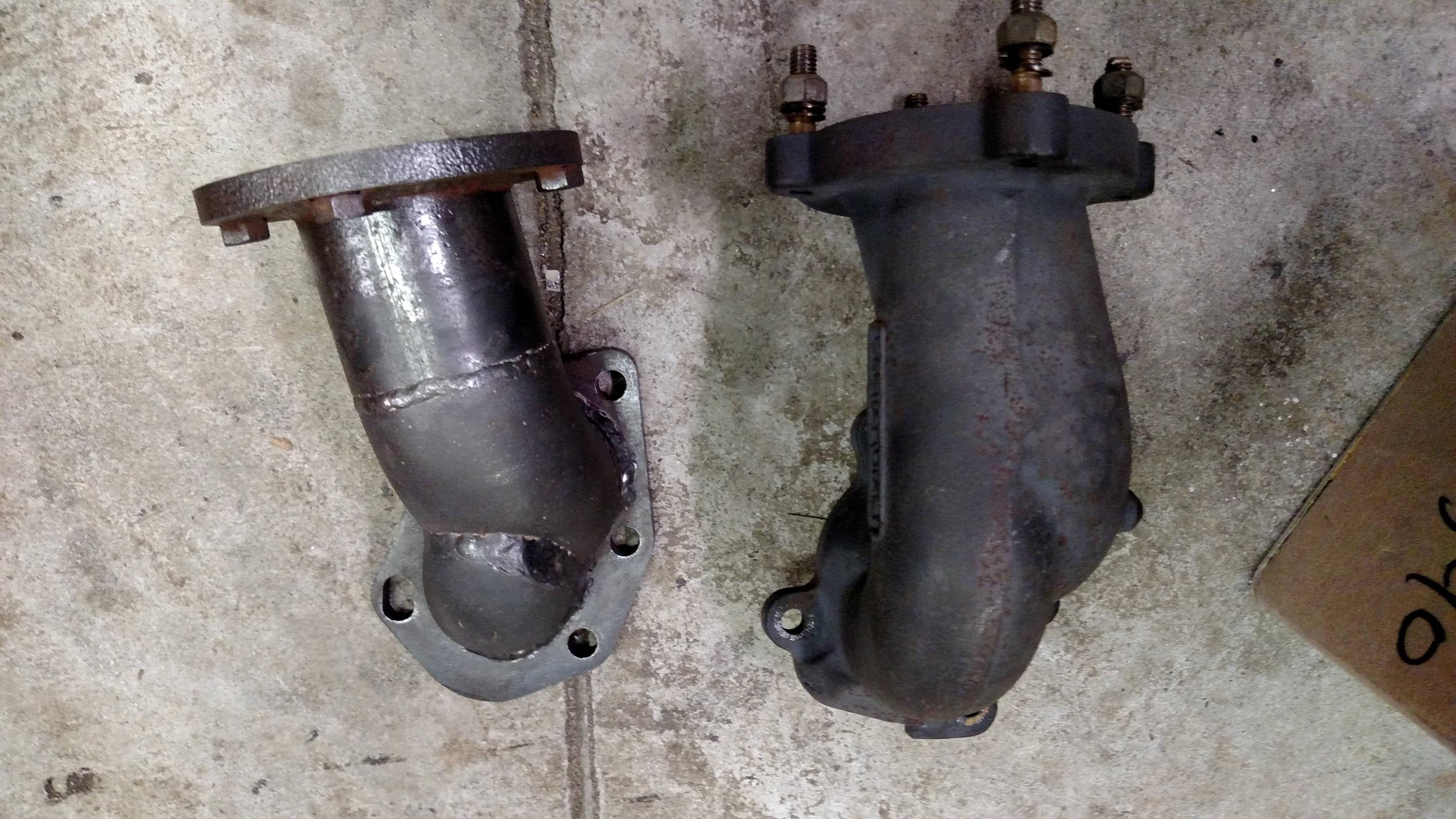
I found this pic (not mine) of two down pipes for this application, the one on the left doesn't seem very large, either, from what I can scale from the picture:
2.25" would work.
2.5" is recommended and most setups use this size.
3" is best but tough to fit.
make the bend downward sharper to clear the shelf.
heater lines can be moved out of the way. And you can cut off the lip of the shelf for some more clearence
Keep in mind, a 2" schedule 40 carbon steel pipe is about the same ID (~2.067" vs ~2.125") as 2.25" exhaust tubing, but quite a bit bigger OD (2.38" vs. 2.25").
I am using thick wall piping and weld ells at the moment, I get the feeling shouldn't. Reading your answers and other topics, should I go to thin wall exhaust tubes? Those 2.5" tubes are actually 2.5", not a lot more. And it seems they are available in a shorter radius, and I can whack them into a prefered shape. Right?
You can buy pretty tight radius pre-bends in any diameter you like. I buy the 180s and cut the amount of bend out that i need. You can go past 90 to get it away from the shelf and water lines then come back below the shelf.
Well, yes considering I need to add 120 buck shipping and 25% import tax and VAT. It'll be 500 bucks before I get my hands on it. And if I can make something myself for a tenth of that price, I think it is worth a shot. Besides that, I like fabricating myself.
Anyway, thanks for all the useful info and data. I have found some 1,5mm wall thickness piping (bends, Y-pipes, reducers from one size to the other, etc) which comes close to what you all recommend. I was just looking at the wrong piping, first, with weld ells and matching tube. All bigger than the name suggests and thick walled.
I'll go do some shopping, now, hope to get the stuff in the weekend.
I'm back! I just posted my progress in my topic ( https://www.miataturbo.net/build-threads-57/hugows-weird-slow-1-6-1-8-non-vvt-diy-project-97747/ ), I am actually making the down pipe! Now the main section is stitch welded together, I am looking at the waste gate routing. And I am wondering if it is at all needed to make a pipe there. I doubt the gate will ever open that far. I made a little clip:
I think the waste gate will never open so far that the valve will actually go past the opening in the flange and let gas flow through there. I think in most cases, the valve will just block the flow to the by pass piping. So, I am considering to block the opening completely by welding on a plate.
Most try to optimize wastegate flow as much as possible.
A poorly flowing Wastegate induces boost creep.
So if you dont care about creep and plan to run your setup at high psi, then no problemo, weld the hole shut, knowing you won't be able to run 8psi boost.
@borka: thanks for the input. I'll make a bypass outlet. I am only aiming at 200 bhp wheel horse power, but I didn't consider the boost creep. Never heard of it before, thanks for teaching me.
Well, the first downpipe didn't end up too well, largely due to two facts: I ground back the welds too much so it became too thin in many places, and I made the downpipe to split into two parts to match the original flange. But after closed examination, the two pips come together after the flange fairly quickly so splitting and re-merging does not make sense. It only complicates the build and gives more back pressure. So, now to move forward; do you know the saying "when all you have is a hammer, you tend to treat every problem as a nail"? Well, I have a 3D printer. So I started drawing up parts, mostly in TinkerCAD:
As you can see I only print angles up to 45 degrees, 90 degree ones I split. This way I can print quickly without supports on that part. 'Welding' the parts together I do with CA glue and accellerator. The flange I drew in FreeCAD, btw, that is too complicated for TinkerCAD. With the first parts printed I started the build:
So far I used the flange, a 48,3 mm bend, a 48,3 mm to 60,3 mm converter, and I am holding a 60,3 mm 45 degree bend. The first bend is sunk into the flange 10 mm, btw, to help with clearance. I am now printing a straight part for between the converter and the big bend. I think that is also the part where I will attach the bypass outlet.
Well, I try to avoid that. And for the 200 whp I am aiming for these diameters more then suffice. Some more progress:
I messed up the bypass bend design, so it was printed perfectly but didn't fit. New ones are going to be printed tomorrow. I will publish the parts in case anyone likes to copy.


 0
0