When you click on links to various merchants on this site and make a purchase, this can result in this site earning a commission. Affiliate programs and affiliations include, but are not limited to, the eBay Partner Network.
I started a long thread, confused myself thoroughly and tossed it all in the trash.
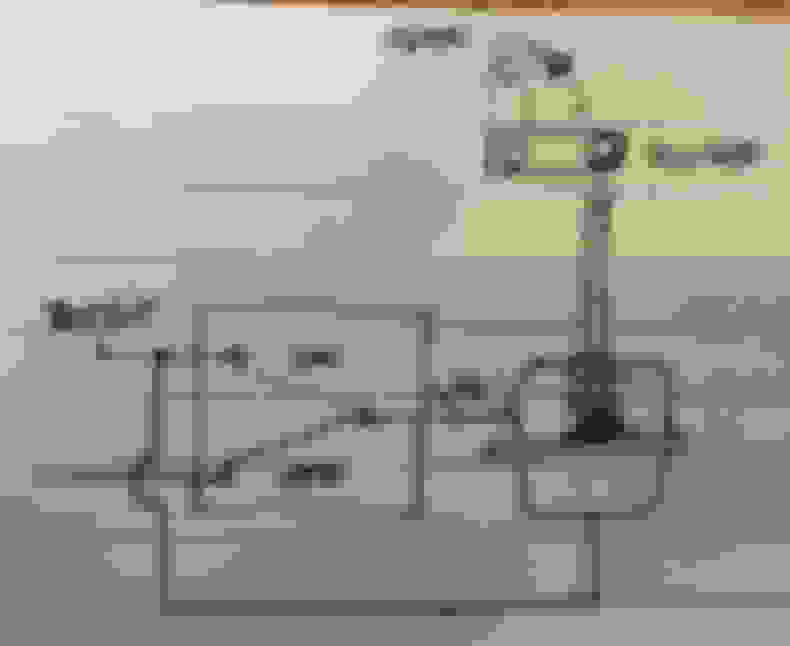
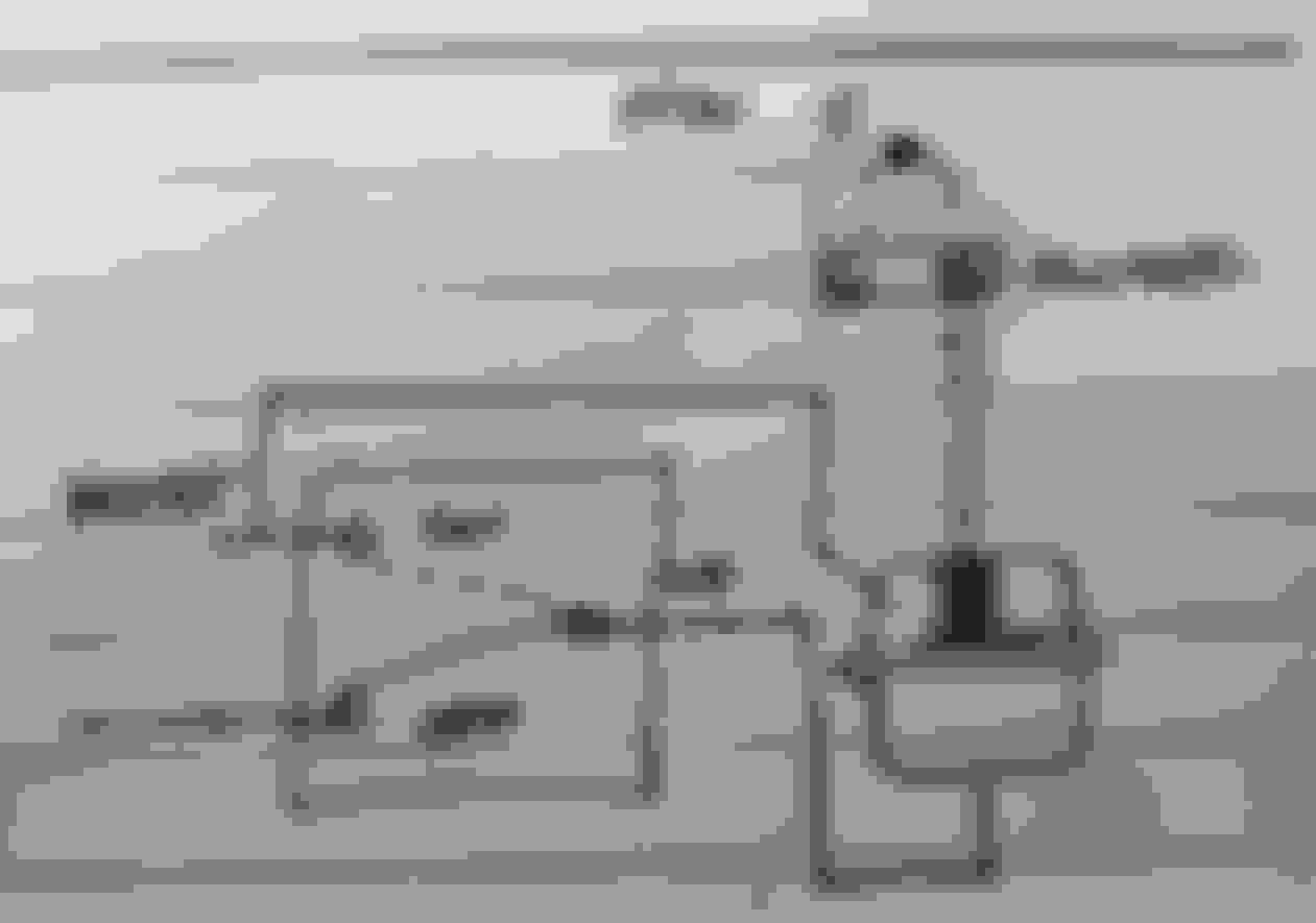
Bottom line...is this right;
Or this (it's an "old-style" solenoid from DIYAutotune;
Every time I try to think this through, I confuse the hell out of myself. Neither way gives me the result I thought I would achieve (WG flapper clamped shut by the actuator, against exhaust pressure until the flapper is allowed open) It seems like the exhaust gas pressure is pushing the flapper open before the actuator responds. I was hoping that a 2-port WG actuator would solve that).
You want normally closed (NC) to connect the boost input port to the non-spring side of the WG, and normally open (NO) to connect the atmo/vent port to the spring side. That way when the power is off to the solenoid you get simple mechanical WG behaviour. When power is on to the solenoid it swaps NC and NO, which both dumps the boost that was trying to open the WG and puts boost on the other side instead, to help the spring keep the WG closed.
You want normally closed (NC) to connect the boost input port to the non-spring side of the WG, and normally open (NO) to connect the atmo/vent port to the spring side. That way when the power is off to the solenoid you get simple mechanical WG behaviour. When power is on to the solenoid it swaps NC and NO, which both dumps the boost that was trying to open the WG and puts boost on the other side instead, to help the spring keep the WG closed.
--Ian
Thanks! This was driving me CRAZY, because I could not see any way that a 3-port solenoid could work.
I much prefer a 3 port (first config) to a 4 port. The second config is all-of-it, all the time. The only time I would consider using a 4 port is if I wanted to get more than ~2.25x the wastegate spring rated pressure. 4 port configurations suffer from 1/2 the resolution in PWM dutycycle and have inferior control. They do have a much higher dynamic range. This for example can allow you to run 20+ psi with a 7psi spring, where you would only be able to reliably get 18psi or so with a 3 port on a 7psi spring. Think boost by gear applications.
The 3 port works like a traditional 2 port setup with 0% dutycycle. The top of the can is at manifold reference, the wastegate opens when manifold pressure reaches spring pressure. When the solenoid is active ("on" in the drawing, or sinking current through the ECU control FET) the lower half of the can pressurizes and pushes the valve back closed. The manifold pressure now has to increase to spring pressure plus the lower can pressure. You are only able to pressurize the lower can with ~80% DC on most solenoids, so this is where the limitation in peak manifold pressure relative to spring pressure originates.
Edit: Decent info here, but keep in mind you want the direct manifold reference line to be connected to the port that opens the WG valve (allowing ex gas to bypass turbine) when pressurized. For an IWG this is usually the top of the can, for EWG this is usually the lower bowl.
Last edited by Ted75zcar; Jul 14, 2021 at 10:51 PM.
I much prefer a 3 port (first config) to a 4 port. The second config is all-of-it, all the time. The only time I would consider using a 4 port is if I wanted to get more than ~2.25x the wastegate spring rated pressure. 4 port configurations suffer from 1/2 the resolution in PWM dutycycle and have inferior control. They do have a much higher dynamic range. This for example can allow you to run 20+ psi with a 7psi spring, where you would only be able to reliably get 18psi or so with a 3 port on a 7psi spring. Think boost by gear applications.
The 3 port works like a traditional 2 port setup with 0% dutycycle. The top of the can is at manifold reference, the wastegate opens when manifold pressure reaches spring pressure. When the solenoid is active ("on" in the drawing, or sinking current through the ECU control FET) the lower half of the can pressurizes and pushes the valve back closed. The manifold pressure now has to increase to spring pressure plus the lower can pressure. You are only able to pressurize the lower can with ~80% DC on most solenoids, so this is where the limitation in peak manifold pressure relative to spring pressure originates.
Edit: Decent info here, but keep in mind you want the direct manifold reference line to be connected to the port that opens the WG valve (allowing ex gas to bypass turbine) when pressurized. For an IWG this is usually the top of the can, for EWG this is usually the lower bowl.
Great info here! After reading codrus' response, I rushed out and bought a 4-port MAC control solenoid. But reading your response, and that Engine Basics article, made me reconsider - mostly because of the "poor resolution problem" cited. I had enough struggles getting the PID loop tuned for boost control so I don't want to (necessarily) introduce another variable into the mix. I'll keep the 4-port on standby for now.
One further question before leaving; What effect does the "Inverted" setting have? I tried it both ways on several different occasions, to no (apparent) effect. I rationalized that by saying that the solenoid is "polarity agnostic", so inverting that doesn't matter. Or am I barking up the wrong tree.
You can use a 4-port solenoid in 2, 3, and 4 port WG configurations. Simply plug the appropriate port (usually a 1/8" NPT). I always use 4 port solenoids.
The "Inverted" setting is quite important, and needs to be setup properly. The EBC CL PID algorithm works 1 way. With negative error (actual less than target) the process output (dutycycle "D" in percent) is increased. With positive error (actual greater than target) "D" is reduced. The inverted setting converts "D" to (100 - "D"). The PWM output is a square wave with period 1/frequency where the output is "high" for "D" % of the time and "low" for (100 - "D") % of the time. Typical solenoids are in the non-energized state while the driving signal is "high" and the energized (switched) state when the driving signal is "low" (called low-side-switching). "Inverted" allows you to swap the high and low states. The gotcha is that it is possible to hook the solenoid and WG up incorrectly (where the non-powered, or non-energized state is all-of-it) and then "fix" the problem by flipping the inverted bit. This is not a fail-safe setup, and a fault in the boost control hardware can blow your **** up quick.
Proper setup can be confirmed by showing that at 0% dutycycle in open loop your get WG manifold pressure, and the same goes for an unplugged/disconnected/unpowered solenoid. This verification procedure is best conducted with an air compressor as opposed to road testing.
Just to close the loop (don't you HATE threads that start, get interesting, and then get abandoned?), I ditched the generic dual-port actuator and sprung for a Turbosmart dual-port. Then I used Ted75zcar's advice and verified that "Normal" was the proper setup. A few tuning runs allowed me to set the (admittedly narrow) duty cycle range of the 4-port solenoid and now things seem to be working "as advertised". I can come up to boost as quickly as the Churbo will allow and hold at my setpoint without the wastegate being pushed open by the exhaust.
I'm happy for the time being, because I have some other plans that will affect this going forward.


 0
0


